Instructions: ELECTRONICS STARTER KIT 2 FOR MICRO:BIT Rev 1b.
TABLE OF CONTENTS Parts 3 Making the Projects...................................................................................................4 Getting Started...........................................................................................................6 Project 1. Lighthouse 9 Project 2. Movement Alarm....................................................................................10 Project 3. Color Mixer.............................................................................................12 Project 4. Anemometer............................................................................................14 Project 5. Fan Speed Controller...............................................................................16 Project 6. Clap Controlled Fan................................................................................18 Project 7. Nightlight.................................................................................................19 The Makecode Editor 20 MonkMakesWhatTroubleshooting.......................................................................................................23Next?..............................................................................................................24.............................................................................................................25Page2
PARTS micro:bit, AA battery and USB lead are NOT included in this kit. Before you do anything else, check that your kit includes the following items: 1Quantity MonkMakes Switch for micro:bit (in previous versions of this kit, a Relay for micro:bit was used) 1 MonkMakes RGB LED for micro:bit (mix colors) 1 Set of alligator clip leads (10 leads) to connect things together 1 Small motor with fan 1 Single AA battery box (battery not included) to power the light bulb and fan 1 1V LED bulb module To make use of this kit, you will also need a BBC micro:bit VERSION 2. This kit is designed for Version 2 of the micro:bit. If the micro:bit logo is gold, and there are indents on alligator clip holes, then it is version 2. Otherwise it's version 1. Page 3
MAKING THE PROJECTS
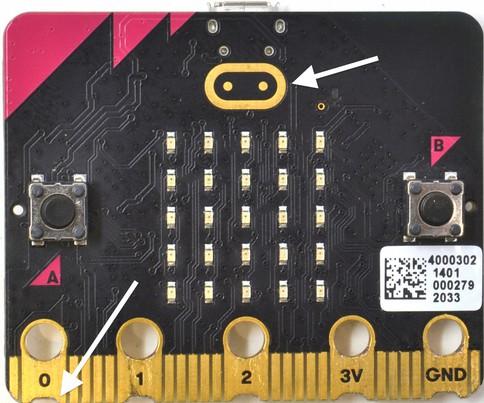
The projects in this kit are assembled by connecting your micro:bit to one or more of the MonkMakes boards using alligator clips. You have to be a bit careful how you connect the clips at the micro:bit end. The correct way is to connect the clips vertically as shown below. Connecting the alligator clips like this prevents any accidental connections between the large connectors with the holes in and the much smaller connectors (gold lines in the photo above) Page 4
Software Before connecting boards to your micro:bit install the program for the project onto the micro:bit. This makes sure that pins are correctly configured as inputs and outputs before you connect up the electronics. This code for this kit uses the Makecode blocks editor. As well as programming by plugging together blocks, you can also view and edit the resulting code as Python or TheJavascript.Blockseditor program allows you to program your micro:bit directly from the browser on your computer. Each program has a web address and clicking on the link in these instructions will open it in your browser so that you can then install it on your micro:bit.
Alligator/Crocodile Clips
Building a Project
The Motor To stop the motor falling over, connect the alligator clips as shown below.
Ifconnections.yourkitcame
The micro:bit and the MonkMakes boards are pretty robust when it comes to connecting things up the wrong way around, but it's a good idea to unplug your micro:bit from your computer while you are wiring things up. Then check it over carefully before connecting your micro:bit to your computer. Each project includes a wiring diagram, like the one below. This shows you what needs to be connected to what. It suggests the colors of lead to be used for each connection. The project will still work just fine, whatever color of lead you use, but it makes it easier to see what's going on if you stick to the color scheme, especially using red for 3V power connections and black for ground with a Relay for micro:bit, rather than a Switch for micro:bit, wire it up as if the diagrams showed a Relay, using the same connection positions. The Relay works just like the Switch, except the Relay does not distinguish between + and -, whereas for the Switches OUT connections it does matter which is + and which is -. Page 5
GETTING STARTED
To install the new program (incidentally the program is called welcome) onto your micro:bit, you first need to open it in the Blocks Editor. You can do this by going to the following page on your computer's web browser by clicking on the link below: https://makecode.microbit.org/_R0YbTwiDs0pE This will open a tab that looks like this: Page 6
Step 1. Plug your micro:bit into your computer. Connect your micro:bit to a free USB port on your computer. If your micro:bit is new, then its LED display will start displaying messages and showing off various features of the micro:bit. You are going to replace this program currently running on your micro:bit with a new one.
To get you started with your kit, please follow the steps below. This does not use any of the MonkMakes add-on boards, so for now you don't need the alligator clips.
Step 2. Open The Blocks Editor
If you have already used your micro:bit for other things, you can probably skip this section.
Now, click on the Edit Code button (top right) to open the program in the Blocks editor as shown below. Step 3. Install the Program
Next, you are going to send the welcome program to the micro:bit. The easiest way to do that is to pair your micro:bit to your computer. This will only work in the Google Chrome browser. To pair your micro:bit, connect it to your computer and then click on the three dots next to the Download button and then select the option Connect device
This will first pop-up some instructions, telling you to connect your micro:bit. Click on the Next button and this will open some more instructions. Click on Next again and then a pop-up will appear near the address area of your browser as shown on the left of the next page. Page 7
Click on whatever your micro:bit is called in the list that appears (something like BBC micro:bit CMSIS-DAP) and then click Connect. From now on, all you have to do to to put a new program onto your micro:bit is to click on the big Download button in the editor. Now click on that Download button to install the Welcome program. Once you click on the Download button, a yellow LED on the back of your micro:bit will start to flicker furiously as the program is flashed onto the micro:bit. As soon as the flashing has finished, the welcome program will start and display the message: Your Electronics Adventure Starts Here!.
Congratulations, you are now ready to move on to Project 1! If you want to learn more about getting programs onto the micro:bit including options if you are not using the Chrome web browser, see: https://microbit.org/get-started/first-steps/set-up/
Page 8
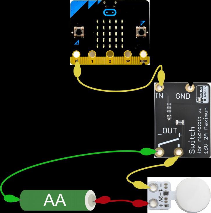
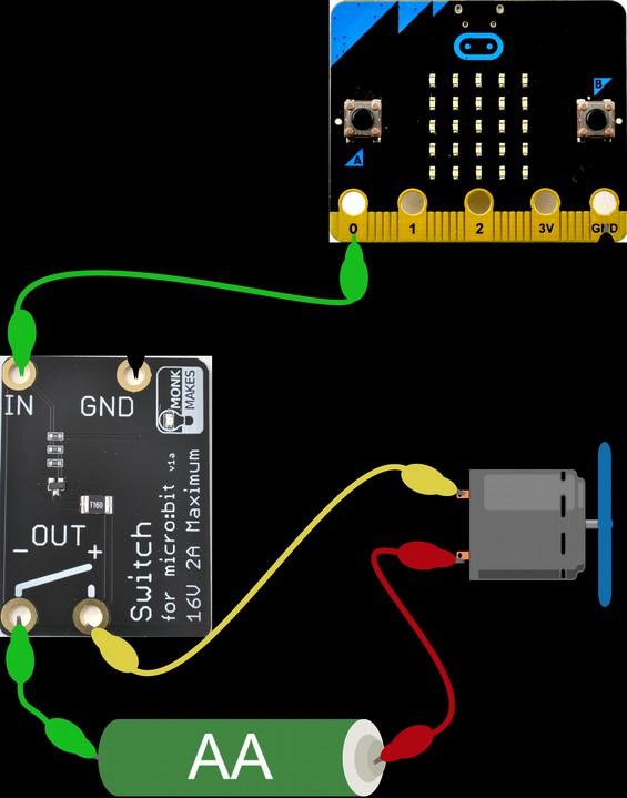
First Pin P0 is turned on using a digital write pin block. The pause block then ensures that it stays on for 1000 milliseconds (1 second) before it is turned off. There then follows another pause of 2 seconds before the cycle repeats itself. Turning the pin P0 on turns the Relay on that completes the circuit, allowing electricity to flow from the battery through the light bulb, making it light up. Page 9
PROJECT 1. LIGHTHOUSE You will need: • micro:bit • MonkMakes Switch or Relay for micro:bit • MonkMakes 1V Bulb • Single AA battery holder and battery • Program: P1 Lighthouse Flash the program P1 Light House onto your micro:bit from the following address: https://makecode.microbit.org/_ft57YJYd7Ky5
Then connect the Switch or Relay for micro:bit, battery and light-bulb as shown above. This project will make the light bulb blink on and off. You might like to make yourself a cardboard structure as the lighthouse and fix the light bulb on top.
How it Works The MonkMakes Switch and Relay are both kinds of electronic switch that can use a tiny current provided by the micro:bit's Pin 0 to control a much higher current circuit formed by the battery and bulb. Here is the code for the project.
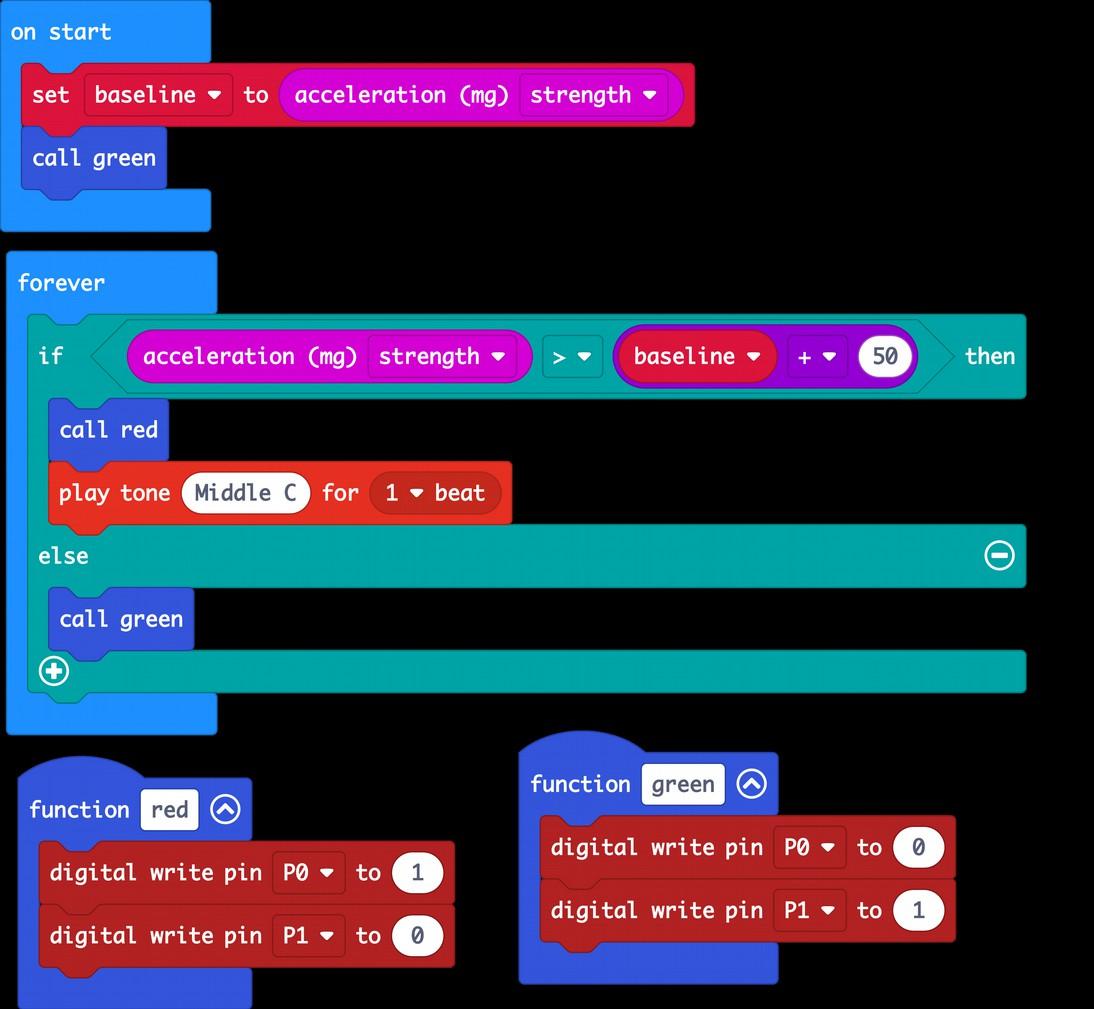
The program uses the micro:bit's built in accelerometer to measure any force acting on it as a result of it moving. When the micro:bit starts running the program, the micro:bit is assumed to be completely still and an initial reading is taken (baseline) but when the micro:bit is picked up, the accelerometer reading will change. Page 10
Then connect the RGB LED as shown to the right. Try moving your micro:bit. As soon as you do, you should hear a tune start to play to indicate that the alarm has been triggered and the RGB LED color will change from Green to Red. How it Works
You RGB LED for micro:bit Program: P2 Movement Alarm Flash the program P2 Movement Alarm onto your micro:bit from the following address: https://makecode.microbit.org/_4Ej08FdLFfku
•
will need: • micro:bit • MonkMakes
PROJECT 2. MOVEMENT ALARM
The functions red and green set the RGB LED color to red or green, by writing a 1 or a 0 to the appropriate pins controlling the RGB LED red and green channels. Try tweaking the number 50 in the if block, to alter how sensitive the alarm is.
The forever loop repeatedly reads the accelerometer strength and if it exceeds the baseline reading by 50, the alarm is sounded.
Page 11
You will need:
Flash the program P3 Color Mixer onto your micro:bit from the link below. When you tilt the micro:bit, the color of the RGB LED will change.
PROJECT 3. COLOR MIXER
How it Works In this project, RGB (Red, Green, Blue) LED is used to display different colors by varying the brightness of the red, green and blue channels of the LED. It does this using the three pins of the micro:bit as PWM (Pulse Width Modulation) Itoutputs.works by varying the duration of a series of pulses sent the red green and blue channels. If the pulse is only high for a very short time (say 5% of the time) then only a small amount of power is delivered to that Page 12
https://makecode.microbit.org/_WyXhYDXe7h6r
•
micro:bit • MonkMakes RGB LED for micro:bit • Program: P3 Color Mixer
This project uses the same connections as Project 2, plus one extra wire from Pin 2 of the micro:bit to Blue on the RGB LED. So, if you have just done Project 2, you just need to add the extra wire. This extra wire is needed because Project 2 only used the red and green channels of the RGB LED, whereas this project uses the red, green and blue.
is acting on the micro:bit then if the micro:bit is completely flat, then the there will be the gravitational force on the Z dimension (up/down) but no forces in the X (left/right) or Y (front/back). However, as soon as you tilt the micro:bit, some of the gravitational pull will be felt on the Y and Y dimensions too. The code reads the X, Y and Z forces separately and uses them to control the brightness of the red, green and blue channels respectively. The constrain block ensures that if the output brightness of each channel does not exceed the maximum value of 1023, or go negative. Page 13
LED color, so it will be dim. The more time the pulse is high, the more power is delivered to the LED color and the brighter it will be. The accelerometer measures forces acting on the micro:bit in the x, y and z Becausedimensions.gravity
PROJECT 4. ANEMOMETER
WARNING: Flash the program P4 Anenometer onto your micro:bit BEFORE connecting up the motor. Failure to do so could damage your micro:bit. Also make sure that you connect the motor as show, with the motor's + connection to micro:bit pin 0. Also, this project if fine for lung power, but a very high speed of rotation could damage your Themicro:bit.program for this project is here: https://makecode.microbit.org/_5KA4KjFhE6z4
You will need:
An anenometer is an instrument for measuring wind speed. In this case, it's going to measure how hard we can blow onto the fan blades.
Blow hard on the fan blade so that they rotate and you should see the micro:bit's display lighting up more, the harder you blow. You can also see a graph of the air speed by clicking on the Show console Device button. This button only appears if you have paired your micro:bit with your computer (see Page 7). When you click on the Show console Device button, you will see a live chart showing the wind speed readings. Page 14
• micro:bit • Motor and Fan • Program: P4 Amenometer
Each set of peeks corresponds to a strong blow onto the fan blade. You could use this to measure the maximum speed to see who can blow the hardest.
Page 15
The forever block uses analog read pin P0 to measure the voltage on pin 0. This number is theoretically (between 0 and 1023), but in practice, unless the fan blade is exposed to hurricane force winds, the maximum reading will be around 250. This number is then sent to your computer over USB using the serial write value block and then a bar graph of the value is shown on the micro:bit display.
How it Works D.C. Motors like the one in this kit, can act as both motors and generators. They are not very efficient and only generate a small amount of power. The voltage that the motor generates will be higher, the faster the fan blades spin.
• min_power – This should be set to the minimum power output value that makes the motor just start to turn. This varies a bit between motors. Try the default value of 600, but if the motor doesn't turn when you press button B to set the speed to 1, you may need to increase this value to perhaps 700 or more. Page 16
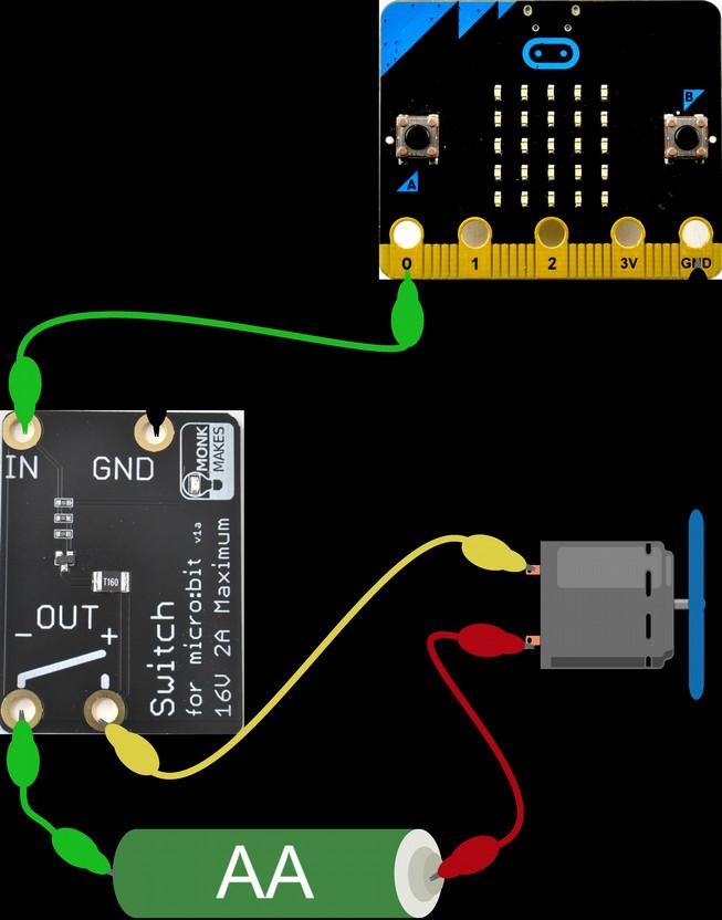
This project uses the MonkMakes Switch or Relay to provide pulses of power of varying length to the motor using PWM (see Project 3).
https://makecode.microbit.org/_UeML9o6bTWhV
Connect up the components as shown to the right. Note it doesn't really matter which way around the motor leads are connected. Reverse them and the motor direction will reverse.
PROJECT 5. FAN SPEED CONTROLLER You will need: • micro:bit • MonkMakes Switch or Relay for micro:bit • AA Battery holder and battery • Motor with fan attached • Program: P5 Fan Speed In this project you will use the motor again, but this time as a motor rather than a Flashgenerator.theprogram
The code is the most complicated so far. It uses quite a few variables that are defined in the on start block.
The micro:bit display will show a number between 0 and 9 indicating the fan's speed. Use button B (on the micro:bit) to increase the speed and button A to decrease the speed. How it Works
P5 Fan Speed onto your micro:bit from the web address below:
• max_power – This is the maximum power, you can leave this as 1023
• Speed – The speed from 0 (off) to 9 (maximum)
• power_step – This is the power range divided by 9 and will be the amount of power change that results from one step more of speed.
The case of the speed being 0 is treated as a special case, to set the power to 0, otherwise the motor may buzz without actually turning when the speed is 0.
The on button pressed blocks are very similar to each other. The block for button A subtracts 1 from speed while making sure that speed does not fall below zero and then displays the new speed and uses analog write to set the power output of pin 0. The on button pressed for B does the same kind of thing, but adding 1 to speed.
The forever loop is used to continuously set the power level to match the speed
Page 17
How it Works
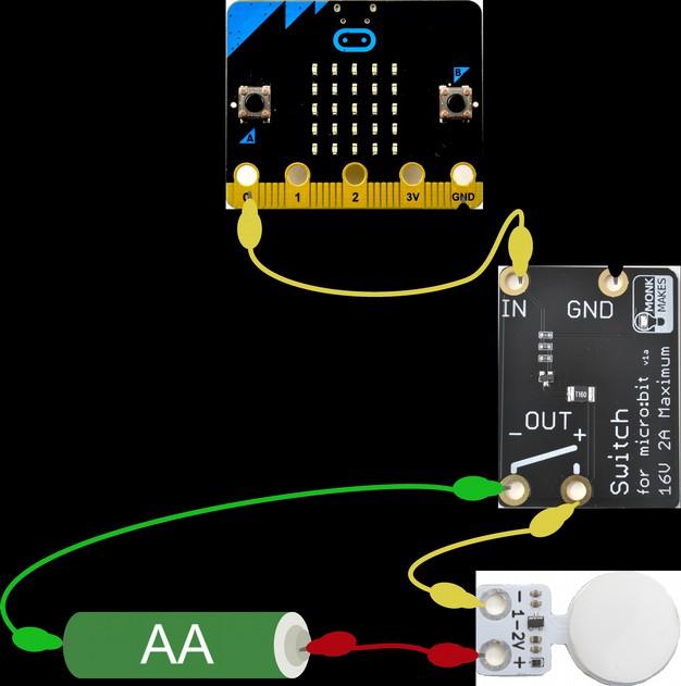
This project would work just as well with the LED lamp, but make sure the + side of the battery goes to the + of the lamp. Page 18
PROJECT 6. CLAP CONTROLLED FAN You will need: • micro:bit • MonkMakes Switch or Relay for micro:bit • AA Battery holder and battery • Motor with fan attached • Program: P6 Clap Controlled Fan
This project uses exactly the same wiring as Project 5, but uses the micro:bit 2's built-in microphone to toggle the motor on and off when a loud noise such as a clap is detected. Clap once to start the fan and then clap again to turn it off. Follow this link for the code for this project: https://makecode.microbit.org/_LszHsFf37P0u
Initially, this is set to false. When a loud sound is detected, the on loud sound block is run. This first uses the not block to set fan to true if it is false and false if it is true, the value of fan on is then used to decide whether to turn the pin 0 (that controls the Relay) on or off (1 or 0).
The Switch or Relay controls the separate circuit of the battery and fan, just like Project 1. The variable fan on is used to control whether the fan is running or not.
This project uses the micro:bit's built-in light sensor to measure the level of light and when it falls below a certain level, it activates the Switch or Relay and turns on the LED lamp. Hold your hand over the micro:bit's display to simulate it going dark. This should cause the LED lamp to turn on.
PROJECT 7. NIGHTLIGHT You will need: • micro:bit • MonkMakes Switch or Relay for micro:bit • AA Battery holder and battery • MonkMakes LED Bulb
• Program: P7 Nightlight
You can find the code for this project here: https://makecode.microbit.org/_YyF41pLhA7wU How it Works Here's the code for the project. If you want it to be darker before the lamp turns on, then change 50 to a lower number.
Page 19
Events The JavaScript language that underpins the Block editor uses something called “events”. The “on start” block that our welcome message appears in is an example of an “event”. The event being that the micro:bit started up, because it was plugged in or its reset button was pressed. Start a new project (by clicking on Projects and then New Project) and delete both the on start and forever blocks. Add an on button pressed (another event) block (in the Input category) and then place a show string block inside it and change the text that the show string block is to display so that it looks like this. Page 20
One really nice feature of the Blocks editor is that the image of a micro:bit on the left of the screen is a virtual micro:bit that you can run your programs on before flashing them onto the micro:bit. You can press its buttons with your mouse, it will display things and if you used the GPIO pins as digital outputs, it will even highlight them when you write to them. You can also click on GPIO pins to simulate digital and analog inputs. The middle section of the screen has different categories of blocks: Basic, Input, Music etc. where you can find blocks to put onto the right-hand ‘canvas’ area. You can also use the Search box just above the list of block categories if you are not sure where to find the block that you want.
THE MAKECODE EDITOR
The Blocks editor is primarily for editing your programs as Blocks. But you can also use it to view or edit your programs in JavaScript or Python programming language if you prefer.
Now, when you use your mouse to click on button A in the virtual micro:bit it will scroll the message. You could also now try this on a real micro:bit.
notice that at the top of the window, there is a tab button labelled JavaScript. This has a drop-down list that you can set to either JavaScript or Python. If you set the dropdown to Python, the blocks disappear from the editor area and the equivalent Python code will be shown.
Page 21
To try this out, open the code for Project 7 (Nightlight). Here's the blocks view of the Youcode.will
JavaScript and Python
You could if you prefer simply write all your code in the Python (or JavaScript) versions of the editor, and you can even drag blocks from the palette into your code where they will appear as Python code.
You can if you like edit the code in this Python view and then switch back to the blocks view, and as long as your code is correct, the change you made in Python will appear in the blocks version. For example try changing 50 in the Python code to 40 and then switch back to the blocks view.
Page 22
Problem: The project doesn't work, but I'm pretty sure I have the right program uploaded and all the wiring looks good. What can I do?
Solution: If you have checked everything and can't find a problem, then it is possible that one of the alligator leads is broken – this can happen if they are overflexed. Try and think about which lead might be faulty and try a different lead.
Problem: I can't flash a program onto my micro:bit
Problem: The LED isn't lit on the MonkMakes Switch or Relay for micro:bit even though I think it's connected correctly.
Problem: The LED bulb does not light.
TROUBLESHOOTING
Page 23
Solution: This is normal. The LED on the Switch and Relay will only light when the relay is activated.
Solution: First check that the micro:bit's power LED is lit. If it isn't try a different USB port or USB lead. If the micro:bit is receiving power, but you can't see the micro:bit drive on your computer, then you may be using a 'power only' USB cable. Try a different cable.
Solution: Make sure that you have the polarity correct, using the wiring diagram and if that does not work, try a fresh AA cell. For other support questions, please check out the product's web page (http://monkmakes.com/mb_kit_2) and you can send support questions to support@monkmakes.com
micro:bit Programming
If you want to learn more about programming the micro:bit in Python, then you should consider buying Simon Monk's book 'Programming micro:bit: Getting Started with MicroPython', which is available from all major book sellers. For a micro:bit project book, take a look at micro:bit for Mad Scientists.Both books are available from Amazon and all good book stores. You can find out more about this and other books by Simon Monk (the designer of this kit) at: http://simonmonk.org or follow him on Twitter where he is @simonmonk2
WHAT NEXT?
Page 24
the
For more information on this kit, product's home page is here:
MONKMAKES
all sorts of kits and gadgets to help with your micro:bit and Raspberry Pi projects. Find out more, as well as where to buy here: https://monkmakes.com you can also follow MonkMakes on Twitter @monkmakes. Page 25
Ashttps://monkmakes.com/mb_kit_2wellasthiskit,MonkMakesmakes


