Counter Modules
General rules for implementation Installation Connecting or disconnecting the standard 15 pin SUB-D connectors of the TSX CTY 2A/ 4A/ 2C modules to/from the encoder and sensor supplies present is not recommended as this may damage the encoder. Some encoders cannot withstand sudden and simultaneous signal and supply power-ups or outages. General wiring instructions Wire sections Use wires of a satisfactory section to avoid drops in voltage (mainly with 5 V) and overheating. Example of falls in voltage for encoders supplied with 5 V with a cable length of 100 meters: Section of the wire
Encoder consumption 50 mA
100 mA
150 mA
200 mA
0.08 mm (gauge 28)
1.1 V
2.2 V
3.3 V
4.4 V
0.12 mm2 (gauge 26)
-
1.4 V
-
-
0.22 mm2 (gauge 24)
-
0.8 V
-
-
0.34 mm2 (gauge 22)
0.25 V
0.5 V
0.75 V
1V
0.5 mm2
0.17 V
0.34 V
0.51 V
0.68 V
1 mm2
0.09 V
0.17 V
0.24 V
0.34 V
2
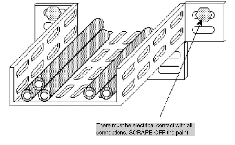
Connection cable All cables carrying the sensor supply (encoders, proximity sensor etc.) and the counting signals must:
be at a distance from high voltage cables, be shielded with the shielding , which is linked to the protective ground connection on both the PLC and encoder side, never carry signals other than counting signals and supplies relating to counting sensors.
The connection cable between the module and encoder should be as short as possible to avoid creating loops, as the circuit capacities can interfere with operation. NOTE: If necessary, direct the flow of the signal in the same cable as the supplies. Cables with twisted pairs should preferably be used for this.
33002439 10/2019
251