Fleitz Continuing Education Jeana Fleitz, M.Ed., RT(R)(M) “The X-Ray Lady” 6511 Glenridge Park Place, Suite 6 Louisville, KY 40222 Telephone (502) 425-0651 Fax (502) 327-7921 Web address www.x-raylady.com Email address xrayladyce@gmail.com
Review of Radiographic Anatomy & Positioning and Pediatric Positioning Approved for 5 Category A Credits
American Society of Radiologic Technologists (ASRT) Course Approval Start Date 01/01/2015 Course Approval End Date 02/01/2017 Florida Radiologic Technology Program FLDOH-BRC Approved for 5 Category A CE Credits (00 –Technical) Course Approval Start Date 12/03/2014 Course Approval End Date 01/31/2017
Please call our office for course renewal status.
A Continuing Education Course for Radiation Operators
Course Directions Completing an X-Ray Lady® homestudy course is easy, convenient, and can be done from the comfort of your own couch. To complete this course read the reference corresponding to your posttest and answer the questions. If you have difficulty in answering any question, refer back to the reference. The test questions correspond with the reading and can be answered as you read through the text. How Do I Submit my Answers?
Transfer your answers to the blank answer sheet provided and fill out your information. Make a copy of your answer sheet for your records Interactive Testing Center: Get your score and download certificate immediately! Sign up on our website by clicking on the “Online Testing” tab or contact our office. Online Answer Sheet: Visit our website and click on the “Online Testing” tab. Answer sheets will be graded in-office daily and certificates emailed within 1-2 business days. Snail Mail: Mail a copy to X-Ray Lady, 6511 Glenridge Park Place Suite 6, Louisville, KY 40222. Allow up to 10 days turnaround time. Fax: If your license expiration date is within 2 weeks of submitting your answers, fax a copy to (502) 327-7921. Please be sure to verify that we received your answer sheet.
Certificate Issuance Your certificate will be scored the same day or next business day. You must score at least a 75% to pass the course. The Interactive Testing Center generates your certificate upon successful completion—please print and save your certificate for your records. If you mail, email, or fax your answer sheet certificates will be emailed unless otherwise noted. Allow five to seven business days for mailed certificates. Reporting Completed Credit Verification of awarded continuing education will be submitted to the radiation control boards of Florida and Kentucky. For the ARRT and all other state licensure agencies, please self-report your earned credits.
®
X-Ray Lady CE Jeana Fleitz, M.Ed., RT(R)(M) 6511 Glenridge Park Place, Suite 6 Louisville, KY 40222 Phone: (502) 425-0651 | Email: xrayladyce@gmail.com Website: www.x-raylady.com
X-Ray Lady® Refund & Exchange Policy Updated March 2015
By placing an order and/or completing a course with X-Ray Lady®, you agree to our refund & exchange policy. The following applies if you do not want your course and have no plans of completing it for credit: Returns or exchanges on unused materials may be made up to 30 days from the original order date. After 30 days, customers may receive a credit to use toward future purchases. Credits expire one year from issue date. All refunds and exchanges are subject to a $5 re-stocking fee per course. Refunds will be issued in the same tender as the original order. Materials purchased with a check will be refunded with a cashier’s check once payment has cleared. Expiring Courses Due to the nature of our courses, no refunds or exchanges are issued for courses expiring within one month of the course approval end date. Courses via USPS No refunds or credits are made for shipping and handling charges once the course has shipped to you. Customer is responsible for all shipping charges to return or exchange course materials. Refunds and exchanges are issued when the materials are received and determined to be in excellent condition. X-Ray Lady® claims no responsibility for any goods lost or stolen in transit or delivery by the U.S. postal service. eBook Courses No refunds will be issued once the materials have been sent. Customers wishing to return an unwanted eBook will have 30 days from the original order date to receive a credit towards a future purchase minus a $5 processing fee. You cannot order a “test only” at a later date for an eBook that you have received a credit for. We do not “buy back” used books. If you return your used materials you will not receive a credit and the materials will be discarded. Requests for lost or deleted eBook links after course completion will be fulfilled up to 6 months after the course completion date.
®
X-Ray Lady CE Jeana Fleitz, M.Ed., RT(R)(M) 6511 Glenridge Park Place, Suite 6 Louisville, KY 40222 Phone: (502) 425-0651 | Email: xrayladyce@gmail.com Website: www.x-raylady.com
Earning CE Credit This activity may be available in multiple formats or from different sponsors. Continuing education credit can be awarded only once for the same activity in the same or any subsequent biennium. This course has been evaluated and approved for a specified amount of continuing education by the agencies listed on the course cover. X-Ray Lady CE® does not imply or guarantee that completion of this course automatically ensures renewal or initial issuance of any state, national, or federal x-ray certification or licensure requirements. It is the responsibility of the individual completing this course to understand and to comply with state, national, and federal x-ray certification and licensure regulations regarding initial and continuing requirements. Further, X-Ray Lady CE® claims no responsibility for determining if the topic or amount of continuing education credit is appropriate for the person completing the course. The field of medical imaging and medicine is ever changing. Readers are advised to check the most current product information provided by equipment and supply manufacturers. X-Ray Lady CE® does not assume any liability for any injury and/or damage to persons or property arising from information contained in this course. The information contained in this course should not be used for medical diagnosis or treatment. Users of this information are encouraged to contact their physician or health care provider for any health related concerns. The X-Ray Lady CE® is neither responsible nor liable for any claim, loss, or damage resulting from the use of this course.
Copyright Notice All rights reserved. No part of this work may be reproduced or transmitted in any form or by any means, electronic or mechanical, including photocopy, recording, or any information storage and retrieval system, without prior expressed permission from X-Ray Lady CE®.
®
X-Ray Lady CE Jeana Fleitz, M.Ed., RT(R)(M) 6511 Glenridge Park Place, Suite 6 Louisville, KY 40222 Phone: (502) 425-0651 | Email: xrayladyce@gmail.com Website: www.x-raylady.com
Review of Radiographic Anatomy & Positioning and Pediatric Positioning Approved for 5 Category A CE Credits Course Description Over time, a radiographer could find themselves in need or want of a “refresher” in principles and practices they use the most in the workplace. This course aims to review basic anatomy structures, common terminology, and common positioning techniques in both adults and pediatric patients in order to provide reinforcement to the foundation the technologist operates in every day on the job. This course is applicable to the new technologist, the seasoned professional, and everyone in between. The principles presented in the text are applicable to even the most routine diagnostic exams. The first half of the course covers anatomy and positioning while the second half focuses exclusively on pediatric radiography, thus making this course the perfect fit for the needs of any imaging professional.
Objectives
1. Identify and describe anatomical structures and systems that pertain to the study and practice of radiology and utilize proper anatomical terminology in relation to positions and projections of the body. 2. Understand and articulate principles instrumental in obtaining and altering radiographic images, both in analog and digital systems with the use of picture archiving and communication systems (PACS). 3. Demonstrate an application of common radiation protection principles and techniques. 4. Articulate general principles that apply specifically to pediatric radiography, including radiation safety, the diagnosis and evaluation of child abuse, immobilization, and bone development. 5. Describe and show proper positioning techniques, standard projections, and typical positions to best visualize desired anatomy in the pediatric chest, skeletal system, and abdomen.
Review of Radiographic Anatomy & Positioning and Pediatric Positioning Approved for 5 Category A CE Credits
This course is based the following chapters from the 8th Edition of the Textbook of Radiographic Positioning & Related Anatomy:
Chapter 1: Terminology, Positioning, and Imaging Principles Chapter 16: Pediatric Radiography
The aforementioned chapters are reprinted with permission and under licensing agreement with Elsevier, Inc. The chapters are from the Textbook of Radiographic Positioning & Related Anatomy, 8th Edition (ISBN 978-0-323-08388-1). Authors Kenneth L. Bontrager and John P. Lampignano.
C H A P T E R
1
Terminology, Positioning, and Imaging Principles C O N T R I B U T I O N S BY Andrew Woodward, MA, RT(R)(CT)(QM) R A D I AT I O N P R OT E C T I O N C O N T R I B U TO R W. R. Hedrick, PhD, FACR C O N T R I B U TO R S TO PA ST E D I T I O N S Cindy Murphy , BHSc, RT(R), ACR, Joseph Popovitch , RT(R), ACR, DHSA, Kathy M. Mar tensen , BS, RT(R), Barry T. Anthony , RT(R), Katrina Lynn Steinsultz , BS, RT(R)(M) R A D I AT I O N P R OT E C T I O N PA ST C O N T R I B U TO R S Richard Geise , PhD, FACR, FAAPM, E. Russel Ritenour , PhD
CONTENTS
PART ONE: TERMINOLOGY AND POSITIONING
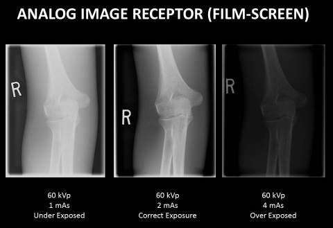
Image quality factors, 37 • Density, 37 • Contrast, 40 • Spatial resolution, 42
General, Systemic, and Skeletal Anatomy and Arthrology
• Distortion, 44
General anatomy, 3 Systemic anatomy, 4 Skeletal anatomy, 7 Arthrology (joints), 11
Image Quality in Digital Radiography Exposure factors, 47 Image quality factors, 48 • Brightness, 48 • Contrast resolution, 48 • Spatial resolution, 49 • Distortion, 49 • Exposure indicator, 49 • Noise, 50 Post-processing, 51
Positioning Terminology General terms, 15 Body planes, sections, and lines, 16 Body surfaces and parts, 17 Radiographic projections, 18 Body positions, 19 Special projection terms, 22 Terms related to movements, 25
Applications of Digital Technology Digital imaging systems, 52 Flat panel detectors, 54 Charged couple device (CCD), 54 Image receptor sizes and orientation, 55 Picture Archiving and Communication System (PACS), 56 Digital imaging glossary, 57
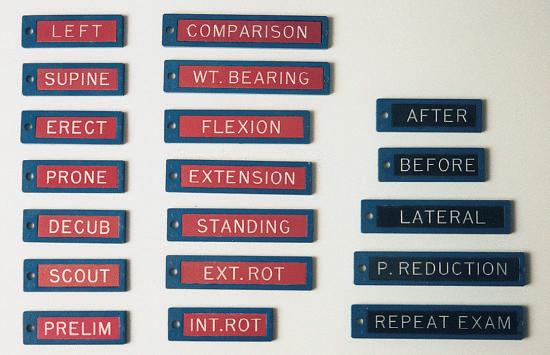
Positioning Principles Evaluation criteria, 30 Image markers and patient identification, 31 Professional ethics and patient care, 32 Essential projections, 33 Principles of positioning, 33 Palpation of positioning landmarks, 35 Viewing images, 35
PART THREE: RADIATION PROTECTION Radiation Units
PART TWO: IMAGING PRINCIPLES
Traditional and SI units, 58 Dose limits, 58 Personnel monitoring, 59
Image Quality in Film-Screen (Analog) Radiography Exposure factors, 36
1
2
C HAPTE R 1 Terminology, Positioning, and Imaging Principles
PART THREE: RADIATION PROTECTION—cont’d 1
Radiation Units—cont’d ALARA, 59 Pregnant technologists, 60 Radiographic patient dose, 60
Patient Protection in Radiography Repeat radiographs, 61 Correct filtration, 61
Accurate collimation, 62 Specific area shielding, 63 Pregnant patient, 64 Minimizing patient dose, 65
Ethical Practice in Digital Imaging Fluoroscopic patient dose, 65 Dose reduction techniques during fluoroscopy, 66 Scattered radiation, 66 Radiation protection during fluoroscopy, 66 Image Wisely, 67
Terminology, Positioning, and Imaging Principles C H A P T E R 1
3
PART ONE: TERMINOLOGY AND POSITIONING GENERAL, SYSTEMIC, AND SKELETAL ANATOMY AND ARTHROLOGY General Anatomy
Anatomy is the study, classification, and description of the structure and organs of the human body, whereas physiology deals with the processes and functions of the body, or how the body parts work. In the living subject, it is almost impossible to study anatomy without also studying some physiology. However, radiographic study of the human body is primarily a study of the anatomy of the various systems with less emphasis on the physiology. Consequently, anatomy of the human system is emphasized in this radiographic anatomy and positioning textbook.
Atoms
Molecule Cell
NOTE: Phonetic respelling* of anatomic and positioning terms is included throughout this text to facilitate correct pronunciation of the terms commonly used in medical radiography.
STRUCTURAL ORGANIZATION Several levels of structural organization make up the human body. The lowest level of organization is the chemical level. All chemicals necessary for maintaining life are composed of atoms, which are joined in various ways to form molecules. Various chemicals in the form of molecules are organized to form cells.
Tissue
Organ
Cells
The cell is the basic structural and functional unit of all living tissue. Every single part of the body, whether muscle, bone, cartilage, fat, nerve, skin, or blood, is composed of cells. Tissues
Tissues are cohesive groups of similar cells that, together with their intercellular material, perform a specific function. The four basic types of tissue are as follows: 1. Epithelial (ep˝-i-the′ le-al): Tissues that cover internal and external surfaces of the body, including the lining of vessels and organs, such as the stomach and the intestines 2. Connective: Supportive tissues that bind together and support various structures 3. Muscular: Tissues that make up the substance of a muscle 4. Nervous: Tissues that make up the substance of nerves and nerve centers
System
Organs
When complex assemblies of tissues are joined to perform a specific function, the result is an organ. Organs usually have a specific shape. Examples of organs of the human body are the kidneys, heart, liver, lungs, stomach, and brain.
Organism (10 systems)
System
A system consists of a group or an association of organs that have a similar or common function. The urinary system, consisting of the kidneys, ureters, bladder, and urethra, is an example of a body system. The total body comprises 10 individual body systems. Organism
The 10 systems of the body when functioning together make up the total organism—one living being.
*Mosby’s medical dictionary, ed 8, St. Louis, 2009, Mosby.
Fig. 1-1 Levels of human structural organization.
1
4
C HAPTE R 1 Terminology, Positioning, and Imaging Principles
Systemic Anatomy BODY SYSTEMS 1
The human body is a structural and functional unit made up of 10 lesser units called systems. These 10 systems include (1) skeletal, (2) circulatory, (3) digestive, (4) respiratory, (5) urinary, (6) reproductive, (7) nervous, (8) muscular, (9) endocrine, and (10) integumentary (in-teg˝-u-men′-tar-e). Skeletal System
The skeletal system is an important system for the technologist to study. The skeletal system includes the 206 separate bones of the body and their associated cartilages and joints. The study of bones is termed osteology, whereas the study of joints is called arthrology. The four functions of the skeletal system are as follows: 1. To support and protect many soft tissues of the body 2. To allow movement through interaction with the muscles to form a system of levers 3. To produce blood cells 4. To store calcium
Fig. 1-2 Skeletal system.
Circulatory System
The circulatory system is composed of the following: • The cardiovascular organs—heart, blood, and blood vessels • The lymphatic system—lymph nodes, lymph vessels, lymph glands, and spleen The six functions of the circulatory system are as follows: 1. To distribute oxygen and nutrients to the cells of the body 2. To carry cell waste and carbon dioxide from the cells 3. To transport water, electrolytes, hormones, and enzymes 4. To protect against disease 5. To prevent hemorrhage by forming blood clots 6. To help regulate body temperature Digestive System
The digestive system includes the alimentary canal and certain accessory organs. The alimentary canal is made up of the mouth, pharynx, esophagus, stomach, small intestine, large intestine, and anus. Accessory organs of digestion include the salivary glands, liver, gallbladder, and pancreas. The twofold function of the digestive system is as follows: 1. To prepare food for absorption by the cells through numerous physical and chemical breakdown processes 2. To eliminate solid wastes from the body
Cardiovascular organs
Lymphatic organs
Fig. 1-3 Circulatory system.
Fig. 1-4 Digestive system.
Terminology, Positioning, and Imaging Principles C H A P T E R 1
5
Respiratory System
The respiratory system is composed of two lungs and a series of passages that connect the lungs to the outside atmosphere. The structures that make up the passageway from the exterior to the alveoli of the lung interior include the nose, mouth, pharynx, larynx, trachea, and bronchial tree. The three primary functions of the respiratory system are as follows: 1. To supply oxygen to the blood and eventually to the cells 2. To eliminate carbon dioxide from the blood 3. To assist in regulating the acid-base balance of the blood
1
Urinary System
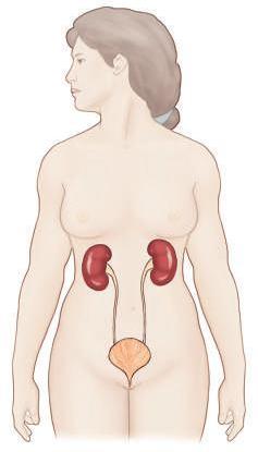
The urinary system includes the organs that produce, collect, and eliminate urine. The organs of the urinary system consist of the kidneys, ureters, bladder, and urethra. The four functions of the urinary system are as follows: 1. To regulate the chemical composition of the blood 2. To eliminate many waste products 3. To regulate fluid and electrolyte balance and volume 4. To maintain the acid-base balance of the body
Fig. 1-5 Respiratory system.
Reproductive System
The reproductive system is made up of organs that produce, transport, and store the germ cells. The testes in the male and the ovaries in the female produce mature germ cells. Transport and storage organs of the male include the vas deferens, prostate gland, and penis. The organs of reproduction in the female are the ovaries, uterine tubes, uterus, and vagina. The function of the reproductive system is to reproduce the organism.
Fig. 1-6 Urinary system.
Male
Female
Fig. 1-7 Reproductive system.
6
C HAPTE R 1 Terminology, Positioning, and Imaging Principles
Nervous System
1
The nervous system is composed of the brain, spinal cord, nerves, ganglia, and special sense organs such as the eyes and ears. The function of the nervous system is to regulate body activities with electrical impulses that travel along various nerves. Muscular System
The muscular system, which includes all muscle tissues of the body, is subdivided into three types of muscles: (1) skeletal, (2) smooth, and (3) cardiac. Most of the muscle mass of the body is skeletal muscle, which is striated and under voluntary control. The voluntary muscles act in conjunction with the skeleton to allow body movement. About 43% of the weight of the human body is accounted for by voluntary or striated skeletal muscle. Smooth muscle, which is involuntary, is located in the walls of hollow internal organs such as blood vessels, the stomach, and intestines. These muscles are called involuntary because their contraction usually is not under voluntary or conscious control. Cardiac muscle is found only in the walls of the heart and is involuntary but striated. The three functions of muscle tissue are as follows: 1. To allow movement, such as locomotion of the body or movement of substances through the alimentary canal 2. To maintain posture 3. To produce heat
Fig. 1-8 Nervous system.
Endocrine System
The endocrine system includes all the ductless glands of the body. These glands include the testes, ovaries, pancreas, adrenals, thymus, thyroid, parathyroid, pineal, and pituitary. The placenta acts as a temporary endocrine gland. Hormones, which are the secretions of the endocrine glands, are released directly into the bloodstream. The function of the endocrine system is to regulate bodily activities through the various hormones carried by the cardiovascular system.
Fig. 1-9 Muscular system.
Fig. 1-10 Endocrine system.
Terminology, Positioning, and Imaging Principles C H A P T E R 1
7
Integumentary System
The tenth and final body system is the integumentary (in-teg˝-umen′-tar-e) system, which is composed of the skin and all structures derived from the skin. These derived structures include hair, nails, and sweat and oil glands. The skin is an organ that is essential to life. The skin is the largest organ of the body, covering a surface area of approximately 7620 cm2 and constituting 8% of total body mass in the average adult. The five functions of the integumentary system are as follows: 1. Regulate body temperature 2. Protect the body, within limits, against microbial invasion and mechanical, chemical, and ultraviolet (UV) radiation damage 3. Eliminate waste products through perspiration 4. Receive certain stimuli such as temperature, pressure, and pain 5. Synthesize certain vitamins and biochemicals such as vitamin D
Skeletal Anatomy Because a large part of general diagnostic radiography involves examination of the bones and joints, osteology (os˝-te-ol′-o-je) (the study of bones) and arthrology (ar-throl′-o-je) (the study of joints) are important subjects for the technologist.
1
Fig. 1-11 Integumentary system.
OSTEOLOGY The adult skeletal system is composed of 206 separate bones, which form the framework of the entire body. Certain cartilages, such as those at the ends of long bones, are included in the skeletal system. These bones and cartilages are united by ligaments and provide surfaces to which the muscles attach. Because muscles and bones must combine to allow body movement, these two systems sometimes are collectively referred to as the locomotor system. The adult human skeleton is divided into the axial skeleton and the appendicular skeleton. Axial Skeleton
The axial (ak′-se-al) skeleton includes all bones that lie on or near the central axis of the body. The adult axial skeleton consists of 80 bones and includes the skull, vertebral column, ribs, and sternum (the dark-shaded regions of the body skeleton in Fig. 1-12). ADULT AXIAL SKELETON Skull
Cranium Facial bones
Hyoid
Thorax
6 Cervical
7
Thoracic
12
Lumbar
5
Sacral
1
Coccyx
1
Sternum Ribs
Total bones in adult axial skeleton
14 1
Auditory ossicles (small bones in each ear) Vertebral column
8
1 24 80
Fig. 1-12 Axial skeleton—80 bones.
8
C HAPTE R 1 Terminology, Positioning, and Imaging Principles
Appendicular Skeleton
1
The second division of the skeleton is the appendicular (ap˝-endik′-u-lar) portion. This division consists of all bones of the upper and lower limbs (extremities) and the shoulder and pelvic girdles (the dark-shaded regions in Fig. 1-13). The appendicular skeleton attaches to the axial skeleton. The adult appendicular skeleton comprises 126 separate bones.
ADULT APPENDICULAR SKELETON Shoulder girdles Upper limbs
Clavicles
2
Scapula (scapulae)
2
Humerus (humeri)
2
Ulna (ulnae)
2
Radius (radii)
2
Carpals
16
Metacarpals
10
Phalanges
28
Pelvic girdle
Hip bones (innominate bones)
2
Lower limbs
Femur (femora)
2
Tibia
2
Fibula (fibulae)
2
Patella (patellae)
2
Tarsals
14
Metatarsals
10
Phalanges
28
Total bones in adult appendicular skeleton
Fig. 1-13 Appendicular skeleton—126 bones.
126
Entire adult skeleton—206 separate bones* *This includes the 2 sesamoid bones at the knees: the right and left patellae.
Sesamoid Bones
A sesamoid bone is a special type of small, oval-shaped bone that is embedded in certain tendons (most often near joints). Although sesamoid bones are present even in a developing fetus, they are not counted as part of the normal axial or appendicular skeleton except for the two patellae, the largest sesamoid bones. The other most common sesamoid bones are located in the posterior foot at the base of the first toe (Figs. 1-14 and 1-15). In the upper limb, sesamoid bones are found most commonly in tendons near the anterior (palmar) surface of the hand at the base of the thumb. Others may be found in tendons of other upper or lower limb joints. Any sesamoid bone can be fractured by trauma; this may have to be demonstrated radiographically or by CT (computed tomography).
Fig. 1-15 Sesamoid bones. Tangential projection (base of first toe).
Extremity
CLASSIFICATION OF BONES Each of the 206 bones of the body can be classified according to shape as follows: • Long bones • Short bones • Flat bones • Irregular bones Long Bones
Body
Fig. 1-14 Sesamoid bones on the posterior base of the first toe. Extremity
Long bones consist of a body and two ends or extremities. Long bones are found only in the appendicular skeleton. (Fig. 1-16 is a radiograph of a humerus, a typical long bone of the upper arm.)
Fig. 1-16 Long bone (humerus).
Terminology, Positioning, and Imaging Principles C H A P T E R 1
Composition The outer shell of most bones is composed of hard
or dense bone tissue known as compact bone, or cortex, meaning an external layer. Compact bone has few intercellular empty spaces and serves to protect and support the entire bone. The body (older term is shaft) contains a thicker layer of compact bone than is found at the ends, to help resist the stress of the weight placed on them. Inside the shell of compact bone and especially at both ends of each long bone is found spongy, or cancellous, bone. Cancellous bone is highly porous and usually contains red bone marrow, which is responsible for the production of red blood cells. The body of a long bone is hollow. This hollow portion is known as the medullary (med′-u-lar˝-e) cavity. In adults, the medullary cavity usually contains fatty yellow marrow. A dense fibrous membrane, the periosteum (per˝-e-os′-te-am), covers bone except at the articulating surfaces. The articulating surfaces are covered by a layer of hyaline cartilage. Hyaline (hi′-ah-lin), meaning glassy or clear, is a common type of cartilage or connecting tissue that is also known as “gristle.” Its name comes from the fact that it is not visible with ordinary staining techniques, and it appears “clear” or glassy in laboratory studies. It is present in many places, including within the covering over ends of bones, where it is called articular cartilage. The periosteum is essential for bone growth, repair, and nutrition. Bones are richly supplied with blood vessels that pass into them from the periosteum. Near the center of the body of long bones, a nutrient artery passes obliquely through the compact bone via a nutrient foramen into the medullary cavity.
Articular (hyaline) cartilage
1 Compact bone
Spongy or cancellous bone (contains red marrow)
Medullary cavity
Periosteum Nutrient foramen Nutrient artery
Body
Fig. 1-17 Long bone.
Short Bones
Short bones are roughly cuboidal and are found only in the wrists and ankles. Short bones consist mainly of cancellous tissue with a thin outer covering of compact bone. The eight carpal bones of each wrist and the seven tarsal bones of each foot are short bones. Flat Bones
Flat bones consist of two plates of compact bone with cancellous bone and marrow between them. Examples of flat bones are the bones that make up the calvaria (skull cap), sternum, ribs, and scapulae. The narrow space between the inner and the outer table of flat bones within the cranium is known as the diploë (dip′-lo-e). Flat bones provide protection for interior contents and broad surfaces for muscle attachment.
9
Fig. 1-18 Short bones (carpals).
Fig. 1-19 Flat bones (calvaria).
Irregular Bones
Bones that have peculiar shapes are lumped into one final category— irregular bones. Vertebrae, facial bones, bones of the base of the cranium, and bones of the pelvis are examples of irregular bones.
Fig. 1-20 Irregular bone (vertebra).
10
C HAPTE R 1 Terminology, Positioning, and Imaging Principles
DEVELOPMENT OF BONES
1
The process by which bones form within the body is known as ossification (os˝-i-fi-ka′-shun). The embryonic skeleton is composed of fibrous membranes and hyaline cartilage. Ossification begins at about the sixth embryonic week and continues until adulthood. Blood Cell Production
In adults, red blood cells (RBCs) are produced by the red bone marrow of certain flat and irregular bones such as the sternum, ribs, vertebrae, and pelvis as well as the ends of the long bones.
Primary center: Diaphysis (body) Secondary centers: Metaphysis Epiphyseal plate
Epiphyses
Bone Formation
Two types of bone formation are known. When bone replaces membranes, the ossification is called intramembranous (in˝-trahmem′-brah-nus). When bone replaces cartilage, the result is endochondral (en˝-do-kon′-dral) (intracartilaginous) ossification. Intramembranous ossification
Intramembranous ossification occurs rapidly and takes place in bones that are needed for protection, such as sutures of the flat bones of the skullcap, which are centers of growth in early bone development. Endochondral ossification
Endochondral ossification, which is much slower than intramembranous ossification, occurs in most parts of the skeleton, especially in the long bones. Primary and Secondary Centers of Endochondral Ossification
The first center of ossification, which is called the primary center, occurs in the midbody area. This primary center of ossification in growing bones is called the diaphysis (di-af′-i-sis). This becomes the body in a fully developed bone. Secondary centers of ossification appear near the ends of the limbs of long bones. Most secondary centers appear after birth, whereas most primary centers appear before birth. Each secondary center of ossification is called an epiphysis (e-pif′-i-sis). Epiphyses of the distal femur and the proximal tibia are the first to appear and may be present at birth in a term newborn. Cartilaginous plates, called epiphyseal plates, are found between the metaphysis and each epiphysis until skeletal growth is complete. The metaphysis is the wider portion of a long bone adjacent to the epiphyseal plate. The metaphysis is the area where bone growth in length occurs. Growth in the length of bones results from a longitudinal increase in these epiphyseal cartilaginous plates. This is followed by progressive ossification through endochondral bone development until all the cartilage has been replaced by bone, at which time growth to the skeleton is complete. This process of epiphyseal fusion of the long bones occurs progressively from the age of puberty to full maturity, which occurs at about 25 years of age. However, the time for each bone to complete growth varies for different regions of the body. On average, the female skeleton matures more quickly than the male skeleton. Extensive charts that list the normal growth patterns of the skeleton are available. Radiograph Demonstrating Bone Growth
Fig. 1-22 shows a radiograph of the knee region of a 6-year-old child. Primary and secondary centers of endochondral ossification or bone growth are well demonstrated and labeled.
Fig. 1-21 Endochondral ossification.
Primary center: Diaphysis (body) Secondary centers: Metaphysis Epiphyseal plate
Epiphyses
Fig. 1-22 Knee region (6-year-old child).
Terminology, Positioning, and Imaging Principles C H A P T E R 1
11
Arthrology (Joints)
3. Gomphoses
The study of joints or articulations is called arthrology. It is important to understand that movement does not occur in all joints. The first two types of joints to be described are immovable joints and only slightly movable joints, which are held together by several fibrous layers, or cartilage. These joints are adapted for growth rather than for movement.
A gomphosis joint is the third unique type of fibrous joint, in which a conical process is inserted into a socket-like portion of bone. This joint or fibrous union—which, strictly speaking, does not occur between bones but between the roots of the teeth and the alveolar sockets of the mandible and the maxillae—is a specialized type of articulation that allows only very limited movement.
CLASSIFICATION OF JOINTS Functional
Joints may be classified according to their function in relation to their mobility or lack of mobility as follows: • Synarthrosis (sin˝-ar-thro′-sis)—immovable joint • Amphiarthrosis (am˝-fe-ar-thro′-sis)—joint with limited movement • Diarthrosis (di˝-ar-thro′-sis)—freely movable joint Structural
The primary classification system of joints, described in Gray’s Anatomy* and used in this textbook, is a structural classification based on the three types of tissue that separate the ends of bones in the different joints. These three classifications by tissue type, along with their subclasses, are as follows: 1. Fibrous (fi′-brus) joints • Syndesmosis (sin˝-des-mo′-sis) • Suture (su′-tur) • Gomphosis (gom-fo′-sis) 2. Cartilaginous (kar˝-ti-laj′-i-nus) joints • Symphysis (sim′-fi-sis) • Synchondrosis (sin˝-kon-dro′-sis) 3. Synovial (si-no′-ve-al) joints Fibrous Joints
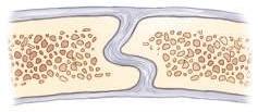
Fibrous joints lack a joint cavity. The adjoining bones, which are nearly in direct contact with each other, are held together by fibrous connective tissue. Three types of fibrous joints are syndesmoses, which are slightly movable; sutures, which are immovable; and gomphoses, a unique type of joint with only very limited movement (Fig. 1-23).
Interosseous ligament
Distal tibiofibular joint 1. Syndesmosis–Amphiarthrodial (slightly movable)
Suture Sutural ligament
Cross-sectional view of suture
Skull suture 2. Suture–Synarthrodial (immovable)
1. Syndesmoses*
Syndesmoses are fibrous types of articulations that are held together by interosseous ligaments and slender fibrous cords that allow slight movement at these joints. Some earlier references restricted the fibrous syndesmosis classification to the inferior tibiofibular joint. However, fibrous-type connections also may occur in other joints such as the sacroiliac junction with its massive interosseous ligaments that in later life become almost totally fibrous articulations. The carpal and tarsal joints of the wrist and foot also include interosseous membranes that can be classified as syndesmosis-type joints that are only slightly movable, or amphiarthrodial. 2. Sutures
Sutures are found only between bones in the skull. These bones make contact with one another along interlocking or serrated edges and are held together by layers of fibrous tissue, or sutural ligaments. Movement is very limited at these articulations; in adults, these are considered immovable, or synarthrodial, joints. Limited expansion- or compression-type movement at these sutures can occur in the infant skull (e.g., during the birthing process). However, by adulthood, active bone deposition partially or completely obliterates these suture lines.
*Standring S et al: Gray’s anatomy, ed 40, Philadelphia, 2009, Churchill Livingstone.
Roots of teeth 3. Gomphosis–Amphiarthrodial (only limited movement)
Fig. 1-23 Fibrous joints—three types.
1
12
C HAPTE R 1 Terminology, Positioning, and Imaging Principles
Cartilaginous Joints
1
Cartilaginous joints also lack a joint cavity, and the articulating bones are held together tightly by cartilage. Similar to fibrous joints, cartilaginous joints allow little or no movement. These joints are synarthrodial or amphiarthrodial and are held together by two types of cartilage—symphyses and synchondroses.
Intervertebral joint (fibrocartilage)
1. Symphyses
The essential feature of a symphysis is the presence of a broad, flattened disk of fibrocartilage between two contiguous bony surfaces. These fibrocartilage disks form relatively thick pads that are capable of being compressed or displaced, allowing some movement of these bones, which makes these joints amphiarthrodial (slightly movable). Examples of such symphyses are the intervertebral disks (between bodies of the vertebrae), which are found between the manubrium (upper portion) and body of the sternum, and the symphysis pubis (between the two pubic bones of the pelvis). 2. Synchondroses
A typical synchondrosis is a temporary form of joint wherein the connecting hyaline cartilage (which on long bones is called an epiphyseal plate) is converted into bone at adulthood. These temporary types of growth joints are considered synarthrodial or immovable. Examples of such joints are the epiphyseal plates between the epiphyses and the metaphysis of long bones and at the three-part union of the pelvis, which forms a cup-shaped acetabulum for the hip joint.
Vertebral body
1. Symphyses Amphiarthrodial (slightly movable)
Epiphyses
Cartilage (epiphyseal plates)
2. Synchondroses Synarthrodial (immovable)
Fig. 1-24 Cartilaginous joints—two types.
Synovial Joints
Synovial joints are freely movable joints, most often found in the upper and lower limbs, which are characterized by a fibrous capsule that contains synovial fluid. The ends of the bones that make up a synovial joint may make contact but are completely separate and contain a joint space or cavity, which allows for a wide range of movement at these joints. Synovial joints are generally diarthrodial, or freely movable. (Exceptions include the sacroiliac joints of the pelvis, which are amphiarthrodial, or slightly movable.) The exposed ends of these bones contain thin protective coverings of articular cartilage. The joint cavity, which contains a viscous lubricating synovial fluid, is enclosed and surrounded by a fibrous capsule that is reinforced by strengthening accessory ligaments. These ligaments limit motion in undesirable directions. The inner surface of this fibrous capsule is thought to secrete the lubricating synovial fluid.
Symphysis pubis (fibrocartilage)
Accessory ligaments
Joint cavity (contains synovial fluid)
Fibrous capsule
Hyaline articular cartilage
Fig. 1-25 Synovial joints—diarthrodial (freely movable).
Movement Types of Synovial Joints There are a considerable
number and variety of synovial joints, and they are grouped according to the seven types of movement that they permit. These are listed in order from the least to the greatest permitted movement. NOTE: The preferred name is listed first, followed by an older term or synonym in parentheses. (This practice is followed throughout this textbook.)
1. Plane (gliding) joints
This type of synovial joint permits the least movement, which, as the name implies, is a sliding or gliding motion between the articulating surfaces. Examples of plane joints are the intermetacarpal, carpometacarpal, and intercarpal joints of the hand and wrist. The right and left lateral atlantoaxial joints between C1 and C2 vertebrae are also classified as plane, or gliding, joints; they permit some rotational movement between these vertebrae, as is described in Chapter 8 .
Intermetacarpal
Intercarpal
Carpometacarpal
Fig. 1-26 Plane (gliding) joints.
Terminology, Positioning, and Imaging Principles C H A P T E R 1
13
2. Ginglymus (hinge) joints
The articular surfaces of ginglymi, or ginglymus (jin′-gli-mus) joints, are molded to each other in such a way that they permit flexion and extension movements only. The articular fibrous capsule on this type of joint is thin on surfaces where bending takes place, but strong collateral ligaments firmly secure the bones at the lateral margins of the fibrous capsule. Examples of ginglymi include the interphalangeal joints of fingers and toes and the elbow joint.
Interphalangeal joints (fingers)
3. Trochoid (pivot) joints
The trochoid (tro′-koid) joint is formed by a bony, pivot-like process that is surrounded by a ring of ligaments or a bony structure or both. This type of joint allows rotational movement around a single axis. Examples of trochoid joints are the proximal and distal radioulnar joints of the forearm, which demonstrate this pivot movement during rotation of the hand and wrist. Another example is the joint between the first and second cervical vertebrae. The dens of the axis (C2) forms the pivot, and the anterior arch of the atlas (C1), combined with posterior ligaments, forms the ring.
1
Elbow joint
Fig. 1-27 Ginglymus (hinge) joints.
C1-2 joint
4. Ellipsoid (condylar) joints
In the ellipsoid (e-lip′-soid) joint, movement occurs primarily in one plane and is combined with a slight degree of rotation at an axis at right angles to the primary plane of movement. The rotational movement is limited by associated ligaments and tendons. This type of joint allows primarily four directional movements: flexion and extension and abduction and adduction. Circumduction movement also occurs; this results from conelike sequential movements of flexion, abduction, extension, and adduction. Examples of ellipsoid joints include the metacarpophalangeal joints of the fingers, the wrist joint, and the metatarsophalangeal joints of the toes.
Proximal and distal radioulnar joints
Fig. 1-28 Trochoid (pivot) joints.
5. Sellar (saddle) joints
The term sellar (sel′-ar), or saddle, describes this joint structure well in that the ends of the bones are shaped concave-convex and are positioned opposite each other (Fig. 1-30). (Two saddle-like structures fit into each other.) Movements of this biaxial type of sellar joint are the same as for ellipsoidal joints—flexion, extension, adduction, abduction, and circumduction. The best example of a true sellar joint is the first carpometacarpal joint of the thumb. Other sellar joints include the ankle and the calcaneocuboid joints. Although the ankle joint was classified as a ginglymus in earlier references, current references classify it as a sellar joint.* *Standring S et al: Gray’s anatomy, ed 40, Philadelphia, 2009, Churchill Livingstone.
Metacarpophalangeal joints (1st to 5th)
Wrist joint
Fig. 1-29 Ellipsoid (condylar) joints.
1st carpometacarpal joint (thumb)
Fig. 1-30 Sellar (saddle) joints.
14
1
C HAPTE R 1 Terminology, Positioning, and Imaging Principles
6. Spheroidal (ball and socket) joints
7. Bicondylar joints*
The spheroidal (sfe′-roid), or ball and socket, joint allows the greatest freedom of motion. The distal bone that makes up the joint is capable of motion around an almost indefinite number of axes, with one common center. The greater the depth of the socket, the more limited is the movement. However, the deeper joint is stronger and more stable. For example, the hip joint is a much stronger and more stable joint than the shoulder joint, but the range of movement is more limited in the hip. Movements of spheroidal joints include flexion, extension, abduction, adduction, circumduction, and medial and lateral rotation. Two examples of ball and socket joints are the hip joint and the shoulder joint.
Bicondylar joints usually provide movement in a single direction. They can permit limited rotation. Bicondylar joints are formed by two convex condyles, which may be encased by a fibrous capsule. Two examples of bicondylar joints are the knee (formerly classified as ginglymus) and the temporomandibular joint (TMJ). *Standring S et al: Gray’s anatomy, ed 40, Philadelphia, 2009, Churchill Livingstone.
TMJ
Knee
Hip joint
Shoulder joint
Fig. 1-31 Spheroidal (ball and socket) joints.
Fig. 1-32 Bicondylar joints.
SUMMARY OF JOINT CLASSIFICATION JOINT CLASSIFICATION
MOBILITY CLASSIFICATION
MOVEMENT TYPES
MOVEMENT DESCRIPTION
EXAMPLES
Syndesmoses
Amphiarthrodial (slightly movable)
—
—
Distal tibiofibular, sacroiliac, carpal, and tarsal joints
Sutures
Synarthrodial (immovable)
—
—
Skull sutures
Gomphoses
Very limited movement
—
—
Areas around roots of teeth
Symphyses
Amphiarthrodial (slightly movable)
—
—
Intervertebral disks
Synchondroses
Synarthrodial (immovable)
—
—
Epiphyseal plates of long bones and between the three parts of the pelvis
Synovial Joints
Diarthrodial (freely movable) except for the sacroiliac joints (synovial joints with only very limited motion [amphiarthrodial])
Plane (gliding)
Sliding or gliding
Intermetacarpal, intercarpal, and carpometacarpal joints, C1 on C2 vertebrae
Ginglymi (hinge)
Flexion and extension
Interphalangeal joints of fingers, toes, and elbow joints
Trochoid (pivot)
Rotational
Proximal and distal radioulnar and between C1 and C2 vertebrae
Ellipsoid (condylar)
Flexion and extension
Metacarpophalangeal and wrist joints
Fibrous Joints
Cartilaginous Joints Symphysis pubis
Abduction and adduction Circumduction Sellar (saddle)
Flexion and extension Abduction and adduction
First carpometacarpal joint (thumb), ankle, and calcaneocuboid joints
Circumduction Spheroidal (ball and socket)
Flexion and extension
Hip and shoulder joints
Abduction and adduction Circumduction Medial and lateral rotation
Bicondylar
Movement primarily in one direction with some limited rotation
Knee and temporomandibular joints
Note: Arthrology, or the study of joints, continues throughout this text as specific anatomy, including all joints of the human body, and is studied in greater detail in subsequent chapters.
Terminology, Positioning, and Imaging Principles C H A P T E R 1
15
POSITIONING TERMINOLOGY Radiographic positioning refers to the study of patient positioning performed for radiographic demonstration or visualization of specific body parts on image receptors (IRs). Each person who plans to work as a radiologic technologist must clearly understand the correct use of positioning terminology. This section lists, describes, and illustrates the commonly used terms consistent with the positioning and projection terminology as approved and published by the American Registry of Radiologic Technologists (ARRT).* These terms, with the exception of the term “view,” are also generally consistent with the terms used in Canada, according to the Canadian Association of Medical Radiation Technologists (CAMRT). (See summary of potentially misused terms at the end of this section.) Throughout this text, named positions (i.e., with the proper name of the person who first described a specific position or procedure) are referred to as methods, such as the Towne, Waters, and Caldwell methods. The ARRT and the CAMRT concur regarding the use of the named method in parentheses after the projection or position term. The description of radiographic positions by the proper name method is becoming less common.
Viewing radiographs A general rule in viewing radiographs is to
display them so that the patient is facing the viewer, with the patient in the anatomic position.
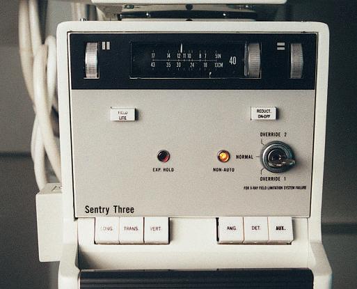
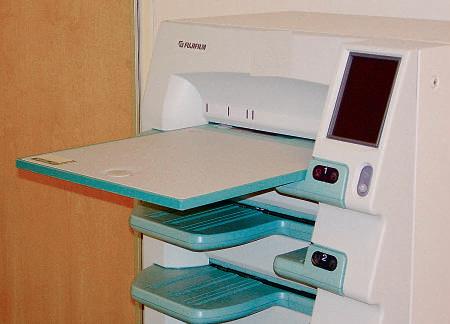
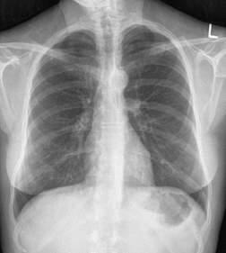
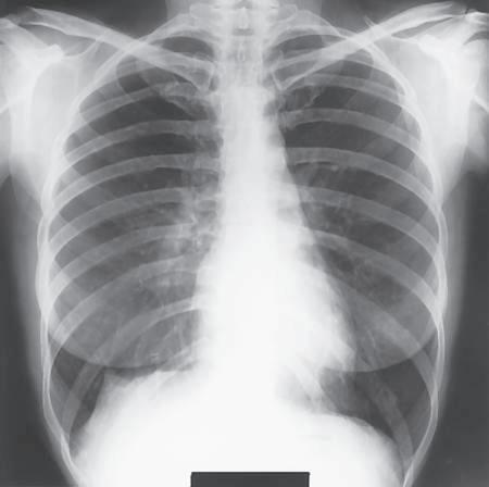
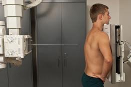
General Terms Radiograph (ra′-de-o-graf ): An image of a patient’s anatomic part(s), as produced by the action of x-rays on an image receptor (Fig. 1-33). If the radiograph is produced with the use of traditional film-screen technology, the image is stored and displayed on film; if the radiograph is produced via digital technology, the image is viewed and stored with the use of computers. Radiography (ra˝-de-og′-rah-fe): The process and procedures of producing a radiograph. Radiograph versus x-ray film: In practice, the terms radiograph and x-ray film (or just film) are often used interchangeably. However, x-ray film specifically refers to the physical piece of material on which a latent (nonprocessed) radiographic image is stored. The term radiograph includes the recording medium and the image. Image receptor (IR): The device that captures the radiographic image that exits the patient; refers to both film-screen cassettes and digital acquisition devices. Central ray (CR): Refers to the center-most portion of the x-ray beam emitted from the x-ray tube; the portion of the x-ray beam that has the least divergence. Radiographic examination or procedure
A radiologic technologist is shown positioning the patient for a routine chest examination or procedure (Fig. 1-34). A radiographic examination involves five general functions: 1. Positioning of body part and alignment with the IR and CR 2. Application of radiation protection measures and devices 3. Selection of exposure factors (radiographic technique) on the control panel 4. Instructions to the patient related to respiration (breathing) and initiation of the x-ray exposure 5. Processing of the IR (film-based [analog] and cassette-based [PSP] system)
L
Fig. 1-33 Chest radiograph.
Fig. 1-34 Radiographic examination.
Anatomic position
The anatomic (an˝-ah-tom′-ik) position is a reference position that defines specific surfaces and planes of the body. The anatomic position is an upright position with arms abducted slightly (down), palms forward, and head and feet directed straight ahead (Fig. 1-35). *ARRT educator’s handbook, ed 3, St. Paul, 1990, The American Registry of Radiologic Technologists; personal communication and correspondence with ARRT, November 1999.
Fig. 1-35 Anatomic position.
1
16
C HAPTE R 1 Terminology, Positioning, and Imaging Principles
Body Planes, Sections, and Lines
1
Sagittal (midsagittal or median) plane
Positioning terms that describe CR angles or relationships between body parts often are related to imaginary planes that pass through the body in the anatomic position. The study of CT, MRI (magnetic resonance imaging), and sonography (diagnostic medical ultrasound) emphasizes sectional anatomy, which also involves the primary body planes and sections as described subsequently.
Oblique plane
PLANE: STRAIGHT LINE SURFACE CONNECTING TWO POINTS
Horizontal (axial) plane
Four common planes as used in medical imaging are as follows: Sagittal plane
A sagittal (saj′-i-tal) plane is any longitudinal plane that divides the body into right and left parts. The midsagittal plane, sometimes called the median plane, is a midline sagittal plane that divides the body into equal right and left parts. It passes approximately through the sagittal suture of the skull. Any plane parallel to the midsagittal or median plane is called a sagittal plane.
Coronal (frontal or midcoronal) plane
Fig. 1-36 Sagittal, coronal, oblique, and horizontal body planes.
Coronal plane
A coronal (ko-ro′-nal) plane is any longitudinal plane that divides the body into anterior and posterior parts. The midcoronal plane divides the body into approximately equal anterior and posterior parts. It is called a coronal plane because it passes approximately through the coronal suture of the skull. Any plane parallel to the midcoronal or frontal plane is called a coronal plane. Horizontal (axial) plane
A horizontal (axial) plane is any transverse plane that passes through the body at right angles to a longitudinal plane, dividing the body into superior and inferior portions. Oblique plane
An oblique plane is a longitudinal or transverse plane that is at an angle or slant and is not parallel to the sagittal, coronal, or horizontal plane.
Oblique transverse plane or section of leg
Transverse (axial or cross-sectional) plane or section of arm
Fig. 1-37 Transverse and oblique sections of body parts.
SECTION: “CUT” OR “SLICE” IMAGE OF BODY PART Longitudinal sections—sagittal, coronal, and oblique
These sections or images run lengthwise in the direction of the long axis of the body or any of its parts, regardless of the position of the body (erect or recumbent). Longitudinal sections or images may be taken in the sagittal, coronal, or oblique plane. Transverse or axial sections (cross-sections)
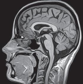
Sectional images are at right angles along any point of the longitudinal axis of the body or its parts. Sagittal, coronal, and axial images CT, MRI, and sonography
images are obtained in these three common orientations or views. (MRI sectional images are shown in Figs. 1-38 through 1-40.)
Fig. 1-38 Sagittal image.
Fig. 1-39 Coronal image.
Fig. 1-40 Transverse (axial) image.
Terminology, Positioning, and Imaging Principles C H A P T E R 1
17
PLANES OF THE SKULL Base plane of skull
This precise transverse plane is formed by connecting the lines from the infraorbital margins (inferior edge of bony orbits) to the superior margin of the external auditory meatus (EAM), the external opening of the ear. This sometimes is called the Frankfort horizontal plane, as used in orthodontics and cranial topography to measure and locate specific cranial points or structures.
1
Base plane
Occlusal plane
Occlusal plane
This horizontal plane is formed by the biting surfaces of the upper and lower teeth with jaws closed (used as a reference plane of the head for cervical spine and skull radiography).
Fig. 1-41 Planes of skull.
Body Surfaces and Parts TERMS FOR THE BACK AND FRONT PORTIONS OF THE BODY Posterior or dorsal
Posterior (pos-te′-re-or) or dorsal (dor′-sal) refers to the back half of the patient, or the part of the body seen when the person is viewed from the back; includes the bottoms of the feet and the backs of the hands as demonstrated in the anatomic position. Anterior or ventral
Anterior surface (ventral)
Posterior surface (dorsal)
Anterior (an-te′-re-or) or ventral (ven′-tral) refers to front half of the patient, or the part seen when viewed from the front; includes the tops of the feet and the fronts or palms of the hands in the anatomic position. Midsagittal plane
TERMS FOR SURFACES OF THE HANDS AND FEET Three terms are used in radiography to describe specific surfaces of the upper and lower limbs. Plantar
Plantar (plan′-tar) refers to the sole or posterior surface of the foot.
Dorsum (dorsum pedis) Plantar surface of foot
Dorsal Foot Dorsal (dor′-sal) refers to the top or anterior surface of the
Fig. 1-42 Posterior vs. anterior.
foot (dorsum pedis). Hand Dorsal also refers to the back or posterior aspect of the
hand (dorsum manus). NOTE: The term dorsum (or dorsal) in general refers to the vertebral or posterior part of the body. However, when used in relationship with the foot, dorsum (dorsum pedis) specifically refers to the upper surface, or anterior aspect, of the foot opposite the sole, whereas for the hand (dorsum manus), it refers to the back or posterior surface opposite the palm.*
Palmar
Palmar (pal′-mar) refers to the palm of the hand; in the anatomic position, the same as the anterior or ventral surface of the hand.* *Mosby’s medical dictionary, ed 8, St. Louis, 2009, Mosby.
Dorsal (posterior, dorsal manus)
Palmar (anterior)
Fig. 1-43 Dorsal and palmar surfaces of hand.
18
C HAPTE R 1 Terminology, Positioning, and Imaging Principles
Radiographic Projections
1
Projection is a positioning term that describes the direction or path of the CR of the x-ray beam as it passes through the patient, projecting an image onto the IR. Although the term position is used in the clinical setting, the term projection is considered to be the most accurate term for describing how the procedure is performed. Therefore, the term projection is used most frequently throughout this text.
Fig. 1-44 PA projection.
COMMON PROJECTION TERMS Posteroanterior (PA) projection
Posteroanterior (pos˝-ter-o-an-te′-re-or) (PA) projection refers to a projection of the CR from posterior to anterior. Combines these two terms, posterior and anterior, into one word, abbreviated as PA. The CR enters at the posterior surface and exits at the anterior surface (PA projection). Assumes a true PA without intentional rotation, which requires the CR to be perpendicular to the coronal body plane and parallel to the sagittal plane, unless some qualifying oblique or rotational term is used to indicate otherwise.
Fig. 1-45 AP projection.
Anteroposterior (AP) projection
Anteroposterior (an˝-ter-o-pos-te′-re-or) (AP) projection refers to a projection of CR from anterior to posterior, the opposite of PA. Combines these two terms, anterior and posterior, into one word. Describes the direction of travel of the CR, which enters at an anterior surface and exits at a posterior surface (AP projection). Assumes a true AP without rotation unless a qualifier term also is used, indicating it to be an oblique projection.
Fig. 1-46 AP oblique projection—medial rotation (from AP).
AP oblique projection
An AP projection of the upper or lower limb that is rotated is called “oblique.” This is not a true AP projection and must also include a qualifying term that indicates which way it is rotated, such as medial or lateral rotation (Fig. 1-46). (For oblique of the whole body, see oblique position descriptions later in this chapter.) With an AP oblique projection, the CR enters the anterior surface and exits the posterior surface of the body or body part.
Fig. 1-48 Mediolateral projection (ankle).
PA oblique projection
A PA projection of the upper limb with lateral rotation (from PA) is shown in Fig. 1-47. (This is applicable to both upper and lower limbs.) This projection is described as a PA oblique. It must also include a qualifying term that indicates which way it is rotated. With a PA oblique projection, the CR enters the posterior surface and exits the anterior surface of the body or body part. Mediolateral and lateromedial projections
A lateral projection is described by the path of the CR. Two examples are the mediolateral projection of the ankle (Fig. 1-48) and the lateromedial projection of the wrist (Fig. 1-49). The medial and lateral sides are determined with the patient in the anatomic position.
Fig. 1-47 PA oblique projection—lateral rotation (from PA).
Fig. 1-49 Lateromedial projection (wrist).
Terminology, Positioning, and Imaging Principles C H A P T E R 1
Body Positions In radiography, the term position is used in two ways, first as general body positions, as described next, and second as specific body positions, which are described in the pages that follow.
19
8. Lithotomy (li-thot′-o-me) position A recumbent (supine) position with knees and hip flexed and thighs abducted and rotated externally, supported by ankle supports.
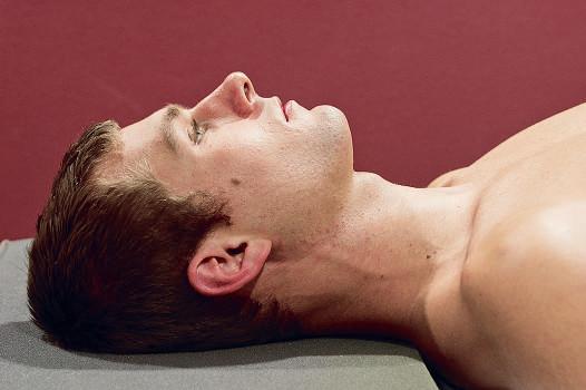
GENERAL BODY POSITIONS The eight most commonly used general body positions in medical imaging are as follows: 1. Supine (soo′-pine) Lying on back, facing upward. 2. Prone (prohn) Lying on abdomen, facing downward (head may be turned to one side). 3. Erect (e˝-reckt′) (upright) An upright position, to stand or sit erect. 4. Recumbent (re-kum′-bent) (reclining) Lying down in any position (prone, supine, or on side). • Dorsal recumbent: Lying on back (supine). • Ventral recumbent: Lying face down (prone). • Lateral recumbent: Lying on side (right or left lateral). 5. Trendelenburg* (tren-del′-en-berg) position A recumbent position with the body tilted with the head lower than the feet. 6. Fowler’s† (fow′-lerz) position A recumbent position with the body tilted with the head higher than the feet. 7. Sims’ position (semiprone position) A recumbent oblique position with the patient lying on the left anterior side, with the right knee and thigh flexed and the left arm extended down behind the back. A modified Sims’ position as used for insertion of the rectal tube for barium enema is shown in Fig. 1-54 (demonstrated in Chapter 13).
Fig. 1-52 Trendelenburg position—head lower than feet.
*Friedrich Trendelenburg, a surgeon in Leipzig, 1844-1924. †George Ryerson Fowler, an American surgeon, 1848-1906.
Fig. 1-53 Fowler’s position—feet lower than head.
Fig. 1-50 Supine position.
Fig. 1-54 Modified Sims’ position.
Fig. 1-51 Prone position.
Fig. 1-55 Modified lithotomy position (for retrograde urography).
1
20
C HAPTE R 1 Terminology, Positioning, and Imaging Principles
SPECIFIC BODY POSITIONS
1
In addition to a general body position, the second way the term position is used in radiography is to refer to a specific body position described by the body part closest to the IR (oblique and lateral) or by the surface on which the patient is lying (decubitus). Lateral position
Lateral (lat′-er-al) position refers to the side of, or a side view. Specific lateral positions described by the part closest to the IR or the body part from which the CR exits (Figs. 1-56 and 1-57). A right lateral position is shown with the right side of the body closest to the IR in the erect position. Fig. 1-57 demonstrates a recumbent left lateral position. A true lateral position is always 90°, or perpendicular, or at a right angle, to a true AP or PA projection. If it is not a true lateral, it is an oblique position. Oblique position
Oblique (ob-lek′, or ob-lik′ )* (oh bleek′, or oh blike′ ) position refers to an angled position in which neither the sagittal nor the coronal body plane is perpendicular or at a right angle to the IR. Oblique body positions of the thorax, abdomen, or pelvis are described by the part closest to the IR or the body part from which the CR exits.
Fig. 1-56 Erect R lateral position.
Fig. 1-57 Recumbent L lateral position.
Left and right posterior oblique (LPO and RPO) positions
Describe the specific oblique positions in which the left or right posterior aspect of the body is closest to the IR. A left posterior oblique (LPO) is demonstrated in both examples (Figs. 1-58 and 1-59). Exit of the CR from the left or right posterior aspect of the body.
Fig. 1-58 Erect LPO position.
Fig. 1-59 Recumbent LPO position.
NOTE: These also can be referred to as AP oblique projections because the CR enters an anterior surface and exits posteriorly. However, this is not a complete description and requires a specific position clarifier such as LPO or RPO position. Therefore, throughout this text, these body obliques are referred to as positions and not projections.
Oblique of upper and lower limbs are described correctly as AP and PA oblique, but require the use of either medial or lateral rotation as a qualifier (see Figs. 1-46 and 1-47). Right and left anterior oblique (RAO and LAO) positions
Refer to oblique positions in which the right or left anterior aspect of the body is closest to the IR and can be erect or recumbent general body positions. (A right anterior oblique [RAO] is shown in both examples (Figs. 1-60 and 1-61). NOTE: These also can be described as PA oblique projections if a position clarifier is added, such as an RAO or LAO position.
It is not correct to use these oblique terms or the abbreviations LPO, RPO, RAO, or LAO as projections because they do not describe the direction or path of the CR; rather, these are positions. *Ob-lek′ is the preferred pronunciation according to Dorland’s Illustrated Medical Dictionary (ed 32), Webster’s New World Dictionary (ed 3), and the American College Dictionary. Ob-lik′ is the second pronunciation, as especially used in the military.
Fig. 1-60 Erect RAO position.
Fig. 1-61 Recumbent RAO position.
Terminology, Positioning, and Imaging Principles C H A P T E R 1
21
Decubitus (decub) position
The word decubitus (de-ku′bi-tus) literally means to “lie down,” or the position assumed in “lying down.”* This body position, meaning to lie on a horizontal surface, is designated according to the surface on which the body is resting. This term describes a patient who is lying on one of the following body surfaces: back (dorsal), front (ventral), or side (right or left lateral). In radiographic positioning, decubitus is always performed with the central ray horizontal.† Decubitus positions are essential for detecting air-fluid levels or free air in a body cavity such as the chest or abdomen, where the air rises to the uppermost part of the body cavity.
1
Right or left lateral decubitus position—AP or PA projection
In this position, the patient lies on the side, and the x-ray beam is directed horizontally from anterior to posterior (AP) (Fig. 1-62) or from posterior to anterior (PA) (Fig. 1-63). The AP or PA projection is important as a qualifying term with decubitus positions to denote the direction of the CR. This position is either a left lateral decubitus (Fig. 1-62) or a right lateral decubitus (Fig. 1-63). It is named according to the dependent side (side down) and the AP or PA projection indication.
Fig. 1-62 Left lateral decubitus position (AP projection).
Dorsal decubitus position—left or right lateral
In this position, the patient is lying on the dorsal (posterior) surface with the x-ray beam directed horizontally, exiting from the side closest to the IR (Fig. 1-64). The position is named according to the surface on which the patient is lying (dorsal or ventral) and by the side closest to the IR (right or left). Ventral decubitus position—right or left lateral
In this position, the patient is lying on the ventral (anterior) surface with the x-ray beam directed horizontally, exiting from the side closest to the IR (Fig. 1-65).
Fig. 1-63 Right lateral decubitus position (PA projection).
*Dorland’s illustrated medical dictionary, ed 32, Philadelphia, 2012, Saunders. †Mosby’s medical dictionary, ed 8, St. Louis, 2009, Mosby.
Fig. 1-64 Dorsal decubitus position (L lateral).
Fig. 1-65 Ventral decubitus position (R lateral).
22
C HAPTE R 1 Terminology, Positioning, and Imaging Principles
Additional Special Use Projection Terms
1
Following are some additional terms that are commonly used to describe projections. These terms, as shown by their definitions, also refer to the path or projection of the CR and are projections rather than positions. Axial projection
Axial (ak′-se-al) refers to the long axis of a structure or part (around which a rotating body turns or is arranged). Special application—AP or PA axial: In radiographic positioning, the term axial has been used to describe any angle of the CR of 10° or more along the long axis of the body or body part.* However, in a true sense, an axial projection would be directed along, or parallel to, the long axis of the body or part. The term semiaxial, or “partly” axial, more accurately describes any angle along the axis that is not truly along or parallel to the long axis. However, for the sake of consistency with other references, the term axial projection is used throughout this text to describe both axial and semiaxial projections as defined earlier and as illustrated in Figs. 1-66 through 1-68.
Fig. 1-66 Axial (superoinferior) projection.
CR 37
Inferosuperior and superoinferior axial projections
Inferosuperior axial projections are frequently performed for the shoulder and hip, where the CR enters below or inferiorly and exits above or superiorly (Fig. 1-68). The opposite of this is the superoinferior axial projection, such as a special nasal bone projection (Fig. 1-66). Tangential projection
Tangential (tan˝-jen′-shal) means touching a curve or surface at only one point. This is a special use of the term projection to describe a projection that merely skims a body part to project that part into profile and away from other body structures.
Fig. 1-67 AP axial (semiaxial) projection (CR 37° caudal).
Examples Following are two examples or applications of the term tangential projection: • Zygomatic arch projection (Fig. 1-69) • Tangential projection of patella (Fig. 1-70) AP axial projection—lordotic position
This is a specific AP chest projection for demonstrating the apices of the lungs. It also is sometimes called the apical lordotic projection. In this case, the long axis of the body rather than the CR is angled. The term lordotic comes from lordosis, a term that denotes curvature of the cervical and lumbar spine (see Chapters 8 and 9). As the patient assumes this position (Fig. 1-71), the lumbar lordotic curvature is exaggerated, making this a descriptive term for this special chest projection. *Frank E, Long B, Smith B: Merrill’s atlas of radiographic positioning & procedures, ed 12, vol 1, St. Louis, 2012, Mosby.
Fig. 1-68 Inferosuperior axial projection.
CR CR
Fig. 1-69 Tangential projection (zygomatic arch).
Fig. 1-70 Tangential projection (patella).
Fig. 1-71 AP axial (apical) lordotic chest projection.
Terminology, Positioning, and Imaging Principles C H A P T E R 1
23
Transthoracic lateral projection (right lateral position)
A lateral projection through the thorax. Requires a qualifying positioning term (right or left lateral position) to indicate which shoulder is closest to the IR and is being examined (Fig. 1-72).
1
NOTE: This is a special adaptation of the projection term, indicating that the CR passes through the thorax even though it does not include an entrance or exit site. In practice, this is a common lateral shoulder projection and is referred to as a right or left transthoracic lateral shoulder.
Dorsoplantar and plantodorsal projections
These are secondary terms for AP or PA projections of the foot. Dorsoplantar (DP) describes the path of the CR from the dorsal (anterior) surface to the plantar (posterior) surface of the foot (Fig. 1-73). A special plantodorsal projection of the heel bone (calcaneus) is called an axial plantodorsal projection (PD) because the angled CR enters the plantar surface of the foot and exits the dorsal surface (Fig. 1-74).
Fig. 1-74 Axial plantodorsal (PD) projection of calcaneus.
Fig. 1-75 Parietoacanthial projection (Waters position).
NOTE: The term dorsum for the foot refers to the anterior surface, dorsum pedis (Fig. 1-42).
Parietoacanthial and acanthioparietal projections
The CR enters at the cranial parietal bone and exits at the acanthion (junction of nose and upper lip) for the parietoacanthial projection (Fig. 1-75). The opposite CR direction would describe the acanthioparietal projection (Fig. 1-76). These are also known as PA Waters and AP reverse Waters methods and are used to visualize the facial bones. Submentovertex (SMV) and verticosubmental (VSM) projections
These projections are used for the skull and mandible. CR enters below the chin, or mentum, and exits at the vertex or top of the skull for the submentovertex (SMV) projection (Fig. 1-77). The less common, opposite projection of this would be the verticosubmental (VSM) projection, entering at the top of the skull and exiting below the mandible (not shown).
Fig. 1-72 Transthoracic lateral shoulder projection (R lateral shoulder position).
Fig. 1-73 AP or dorsoplantar (DP) projection of foot.
Fig. 1-76 Acanthioparietal projection.
Fig. 1-77 Submentovertex (SMV) projection.
24
C HAPTE R 1 Terminology, Positioning, and Imaging Principles
Relationship Terms
1
Following are paired positioning or anatomic terms that are used to describe relationships to parts of the body with opposite meanings. Proximal
Medial versus lateral
Medial (me′-de-al) versus lateral refers to toward versus away from the center, or median plane. In the anatomic position, the medial aspect of any body part is the “inside” part closest to the median plane, and the lateral part is away from the center, or away from the median plane or midline of the body. Examples In the anatomic position, the thumb is on the lateral
Medial plane
Lateral abdomen
Lateral arm Medial arm Lateral hand
aspect of the hand. The lateral part of the abdomen and thorax is the part away from the median plane. Proximal versus distal
Distal
Fig. 1-78 Medial vs. lateral, proximal vs. distal.
Proximal (prok′-si-mal) is near the source or beginning, and distal (dis′-tal) is away from. In regard to the upper and lower limbs, proximal and distal would be the part closest to or away from the trunk, the source or beginning of that limb. Examples The elbow is proximal to the wrist. The finger joint closest to the palm of the hand is called the proximal interphalangeal (PIP) joint, and the joint near the distal end of the finger is the distal interphalangeal (DIP) joint (see Chapter 4). Cephalad versus caudad
Cephalad (sef′-ah-lad) means toward the head end of the body, whereas caudad (kaw′-dad) means away from the head end of the body. A cephalad angle is any angle toward the head end of the body (Figs. 1-79 and 1-81). (Cephalad, or cephalic, literally means “head” or “toward the head.”) A caudad angle is any angle toward the feet or away from the head end (Fig. 1-80). (Caudad or caudal comes from cauda, literally meaning “tail.”) In human anatomy, cephalad and caudad also can be described as superior (toward the head) or inferior (toward the feet).
Fig. 1-79 Cephalad CR angle (toward head).
Fig. 1-80 Caudad CR angle (away from head).
NOTE: As is shown in Figs. 1-79, 1-80, and 1-81, these terms are correctly used to describe the direction of the CR angle for all axial projections along the entire length of the body, not just projections of the head.
Interior (internal, inside) versus exterior (external, outer)
Interior is inside of something, nearer to the center, and exterior is situated on or near the outside. The prefix intra- means within or inside (e.g., intravenous: inside a vein). The prefix inter- means situated between things (e.g., intercostal: located between the ribs). The prefix exo- means outside or outward (e.g., exocardial: something that develops or is situated outside the heart).
Cephalad (superior)
Caudad (inferior)
Fig. 1-81 Cephalic angle (AP axial projection of sacrum).
Superficial versus deep
Superficial is nearer the skin surface; deep is farther away. Example The cross-sectional drawing in Fig. 1-82 shows that the
humerus is deep compared with the skin of the arm. Another example would be a superficial tumor or lesion, which is located near the surface, compared with a deep tumor or lesion, which is located deeper within the body or part. Ipsilateral versus contralateral
Skin (superficial)
Humerus (deep)
Ipsilateral (ip˝-si-lat′-er-al) is on the same side of the body or part; contralateral (kon˝-trah-lat′-er-al) is on the opposite side. Example The right thumb and the right great toe are ipsilateral;
the right knee and the left hand are contralateral.
Fig. 1-82 Cross-section of arm.
Terminology, Positioning, and Imaging Principles C H A P T E R 1
Terms Related to Movements The final group of positioning and related terms that every technologist should know relates to various movements. Most of these are listed as paired terms that describe movements in opposite directions.
25
Flexion
1
Flexion
Flexion versus extension
When a joint is flexed or extended, the angle between parts is decreased or increased. Flexion decreases the angle of the joint (see examples of knee, elbow, and wrist flexions in Fig. 1-83). Extension increases the angle as the body part moves from a flexed to a straightened position. This is true for the knee, elbow, and wrist joints, as is shown.
Extension
Extension
Fig. 1-83 Flexion vs. extension.
Hyperextension
Extending a joint beyond the straight or neutral position. Abnormal hyperextension A hyperextended elbow or knee results
Extension (neutral)
Hyperextension
Flexion
when the joint is extended beyond the straightened or neutral position. This is not a natural movement for these two joints and results in injury or trauma. Normal flexion and hyperextension of spine Flexion is bending
forward, and extension is returning to the straight or neutral position. A backward bending beyond the neutral position is hyperextension. In practice, however, the terms flexion and extension are commonly used for these two extreme flexion and hyperextension projections of the spine (Fig. 1-84).
Fig. 1-84 Hyperextension, extension, and flexion of spine.
Normal hyperextension of wrist A second example of a special
use of the term hyperextension concerns the wrist, where the carpal canal or carpal tunnel view of the carpals is visualized by a special hyperextended wrist movement in which the wrist is extended beyond the neutral position. This specific wrist movement is also called dorsiflexion (backward or posterior flexion) (Fig. 1-85, left). Acute flexion of wrist An acute or full flexion of the wrist is
required for a special tangential projection for a carpal bridge view of the posterior aspect of the wrist (Fig. 1-85, right). Ulnar deviation versus radial deviation of wrist
Deviation literally means “to turn aside” or “to turn away from the standard or course.”* Ulnar deviation is to turn or bend the hand and wrist from the natural position toward the ulnar side, and radial deviation is toward the radial side of the wrist. NOTE: Earlier editions of this textbook and other positioning references have defined these wrist movements as ulnar and radial flexion movements because they describe specific flexion movements toward either the ulna or the radius.† However, because practitioners in the medical community, including orthopedic physicians, commonly use the terms ulnar and radial deviation for these wrist movements, this text also has changed this terminology to ulnar and radial deviation movements to prevent confusion and to ensure consistency with other medical references.
Hyperextension or dorsiflexion
Acute flexion
Fig. 1-85 Wrist hyperextension and flexion movements.
*Dorland’s illustrated medical dictionary, ed 32, Philadelphia, 2012, Saunders. †Frank ED, Ballinger PW, Bontrager KL: Two terms, one meaning, Radiologic Technology 69:517, 1998.
Ulna Ulnar deviation
Radius Radial deviation
Fig. 1-86 Ulnar vs. radial deviation wrist movements.
26
C HAPTE R 1 Terminology, Positioning, and Imaging Principles
Dorsiflexion versus plantar flexion of foot Dorsiflexion of foot To decrease the angle (flex) between the
1
dorsum (top of foot) and the lower leg, moving foot and toes upward. Plantar flexion of foot Extending the ankle joint, moving foot
and toes downward from the normal position; flexing or decreasing the angle toward the plantar (posterior) surface of the foot. NOTE: See preceding page for dorsiflexion of the wrist (Fig. 1-85) compared with dorsiflexion of the foot (Fig. 1-87).
Plantar flexion
Dorsiflexion
Fig. 1-87 Movements of ankle and foot. Eversion versus inversion
Eversion (e-ver’-zhun) is an outward stress movement of the foot at the ankle joint. Inversion (in-ver’-zhun) is inward stress movement of the foot as applied to the foot without rotation of the leg. The plantar surface (sole) of the foot is turned or rotated away from the median plane of the body (the sole faces in a more lateral direction) for eversion and toward the median plane for inversion (Figs. 1-88 and 1-89). The leg does not rotate, and stress is applied to the medial and lateral aspects of the ankle joint for evaluation of possible widening of the joint space (ankle mortise).
Fig. 1-88 Eversion (valgus stress).
Valgus versus varus
Valgus (val′-gus) describes the bending of the part outward or away from the midline of the body. Valgus sometimes is used to describe eversion stress of the ankle joint. Varus (va′-rus), meaning “knock-kneed,” describes the bending of a part inward or toward the midline. The term varus stress sometimes is used to describe inversion stress applied at the ankle joint. NOTE: The terms valgus and varus also are used to describe the loss of alignment of bone fragments. (See Chapter 15.)
Fig. 1-89 Inversion (varus stress).
Medial (internal) rotation versus lateral (external) rotation
Medial rotation is a rotation or turning of a body part with movement of the anterior aspect of the part toward the inside, or median, plane. Lateral rotation is a rotation of an anterior body part toward the outside, or away from the median plane. NOTE: In radiographic positioning, these terms describe movement of the anterior aspect of the part that is being rotated. In the forearm movements (Fig. 1-90), the anterior aspect of the forearm moves medially or internally on medial rotation and laterally or externally on lateral rotation. Another example is the medial and lateral oblique projections of the knee, in which the anterior part of the knee is rotated medially and laterally in either AP or PA projections (see Chapter 6).
A
Medial rotation
B
Lateral rotation
Fig. 1-90 Rotational movements of upper limb. A, Medial (internal) rotation. B, Lateral (external) rotation.
Terminology, Positioning, and Imaging Principles C H A P T E R 1
27
Abduction versus adduction
Abduction (ab-duk′-shun) is the lateral movement of the arm or leg away from the body. Another application of this term is the abduction of the fingers or toes, which means spreading them apart. Adduction (ah-duk′-shun) is a movement of arm or leg toward the body, to draw toward a center or medial line. Adduction of the fingers or toes means moving them together or toward each other.
1
NOTE: A memory aid that can be used is to associate the d in toward with the d in adduction.
Supination versus pronation
Supination (su˝-pi-na′-shun) is a rotational movement of the hand into the anatomic position (palm up in supine position or forward in erect position). This movement rotates the radius of the forearm laterally along its long axis. Pronation (pro-na′-shun) is a rotation of the hand into the opposite of the anatomic position (palm down or back).
Abduction (away from)
Adduction (toward)
Fig. 1-91 Movements of upper limb.
NOTE: To help remember these terms, relate them to the body positions of supine and prone. Supine or supination means face up or palm up, and prone or pronation means face down or palm down.
Protraction versus retraction
Protraction (pro-trak′-shun) is a movement forward from a normal position. Retraction (re-trak′-shun) is a movement backward or the condition of being drawn back. Example Protraction is moving the jaw forward (sticking the chin
out) or drawing the shoulders forward. Retraction is the opposite of this—that is, moving the jaw backward or squaring the shoulders, as in a military stance.
Supination
Pronation
Fig. 1-92 Movements of hand.
Protraction
Retraction
Fig. 1-93 Movements of protraction and retraction.
28
C HAPTE R 1 Terminology, Positioning, and Imaging Principles
Elevation versus depression
1
Elevation
Depression
Elevation is a lifting, raising, or moving of a part superiorly. Depression is a letting down, lowering, or moving of a part inferiorly. Example Shoulders are elevated when they are raised, as when
shrugging the shoulders. Depressing the shoulders is lowering them. Circumduction
Circumduction (ser˝-kum-duk′-shun) means to move around in the form of a circle. This term describes sequential movements of flexion, abduction, extension, and adduction, resulting in a cone-type movement at any joint where the four movements are possible (e.g., fingers, wrist, arm, leg). Rotation versus Tilt
Rotate is to turn or rotate a body part on its axis. In Fig. 1-96, the midsagittal plane of the entire body, including the head, is rotated. Tilt is a slanting or tilting movement with respect to the long axis. Fig. 1-97 demonstrates no rotation of the head but a tilting (slanting) of the midsagittal plane of the head, which therefore is not parallel to the tabletop. Understanding the difference between these two terms is important in skull and facial bone positioning (see Chapter 11).
Fig. 1-94 Elevation and depression movements of shoulders.
Fig. 1-95 Circumduction movements.
Fig. 1-96 Rotation—midsagittal plane rotated.
Fig. 1-97 Tilt—midsagittal plane of head tilted.
Terminology, Positioning, and Imaging Principles C H A P T E R 1
Summary of Potentially Misused Positioning Terms The three terms position, projection, and view are sometimes confusing and may be used incorrectly in practice. These terms should be understood and used correctly. Position
Position is a term that is used to indicate the patient’s general physical position, such as supine, prone, recumbent, or erect. Position also is used to describe specific body positions by the body part closest to the IR, such as lateral and oblique. The term position should be “restricted to discussion of the patient’s physical position.”* Projection
Projection is a correct positioning term that describes or refers to the path or direction of the central ray (CR), projecting an image onto an image receptor (IR). The term projection should be “restricted to discussion of the path of the central ray.”*
29
SUMMARY OF PROJECTIONS AND POSITIONS PROJECTIONS (PATH OF CR)
GENERAL BODY POSITIONS
SPECIFIC BODY POSITION (PART CLOSEST TO IR)
Posteroanterior (PA)
Anatomic
R or L lateral
Anteroposterior (AP)
Supine
Oblique
Mediolateral
Prone
Left posterior oblique (LPO)
Lateromedial
Erect (upright)
Right posterior oblique (RPO)
AP or PA oblique
Recumbent
Left anterior oblique (LAO)
AP or PA axial
Trendelenburg
Right anterior oblique (RAO)
Tangential
Sims’
Decubitus
Transthoracic
Fowler’s
Left lateral decubitus
Dorsoplantar (DP)
Lithotomy
Right lateral decubitus
Plantodorsal (PD)
Ventral decubitus
Inferosuperior axial
Dorsal decubitus
Superoinferior axial
Lordotic
Axiolateral Submentovertex (SMV) Verticosubmental (VSM) Parietoacanthial
View
View is not a correct positioning term in the United States. View describes the body part as seen by the IR or other recording medium, such as a fluoroscopic screen. In the United States, the term view should be “restricted to discussion of a radiograph or image.”* *ARRT 2012 radiography certification handbook, attachment B, St. Paul, 2012, ARRT.
Acanthioparietal Craniocaudal
SUMMARY OF POSITIONING-RELATED TERMS BODY PLANES, SECTIONS, AND LINES
RELATIONSHIP TERMS
Longitudinal planes or sections
Medial vs. lateral
Sagittal
Proximal vs. distal
Coronal
Cephalad vs. caudad
Oblique
Ipsilateral vs. contralateral
Transverse planes or sections
Internal vs. external
Horizontal, axial, or cross-section
Superficial vs. deep
Oblique
Lordosis vs. kyphosis (scoliosis)
Base plane
MOVEMENT TERMS
Occlusal plane
Flexion vs. extension (acute flexion vs. hyperextension)
Infraorbitomeatal line (IOML)
Ulnar vs. radial deviation
BODY SURFACES
Dorsiflexion vs. plantar flexion
Posterior
Eversion vs. inversion
Anterior
Valgus vs. varus
Plantar
Medial vs. lateral rotation
Dorsum
Abduction vs. adduction
Palmar
Supination vs. pronation Protraction vs. retraction Elevation vs. depression Tilt vs. rotation Circumduction
Fig. 1-98 Viewing digital images on monitor.
Cephalad vs. caudad
1
30
C HAPTE R 1 Terminology, Positioning, and Imaging Principles
POSITIONING PRINCIPLES 1
Evaluation Criteria
The goal of every technologist should be to take not just a “passable” radiograph but rather an optimal one that can be evaluated by a definable standard, as described under evaluation criteria. An example of a four-part radiographic image evaluation as used in this text for a lateral forearm is shown on the right. The positioning photo and the resulting optimal radiograph (Figs. 1-99 and 1-100) are shown for this lateral forearm, as described in Chapter 4.
EVALUATION CRITERIA FORMAT The technologist should review and compare radiographs using this standard to determine how close to an optimal image was achieved. A systematic method of learning how to critique radiographs is to break the evaluation down into these four parts. 1. Anatomy demonstrated: Describes precisely what anatomic parts and structures should be clearly visualized on that image (radiograph). 2. Position: Generally evaluates four issues: (1) placement of body part in relationship to the IR, (2) positioning factors that are important for the projection, (3) correct centering of anatomy, and (4) collimation 3. Exposure: Describes how exposure factors or technique (kilovoltage [kV], milliamperage [mA], and time) can be evaluated for optimum exposure for that body part. No motion is a first priority, and a description of how the presence or absence of motion can be determined is listed. (Motion is included with exposure criteria because exposure time is the primary controlling factor for motion.) 4. Image markers: A fourth area of evaluation involves image markers. Anatomic side markers, “Right” or “Left,” patient position, or time markers must be placed correctly before exposure so that they are not superimposed over essential anatomy.
Fig. 1-99 Accurate positioning for lateral forearm.
SAMPLE LATERAL FOREARM CRITERIA EVALUATION CRITERIA
Anatomy Demonstrated: • Lateral projection of entire radius and ulna; proximal row of carpals, elbow, and distal end of humerus; and pertinent soft tissues such as fat pads and stripes of wrist and elbow joints Position: • Long axis of forearm aligned with long axis of IR • Elbow flexed 90° • No rotation from true lateral as evidenced by the following: • Head of the ulna should be superimposed over the radius • Humeral epicondyles should be superimposed • Radial head should superimpose the coronoid process with radial tuberosity seen in profile • Collimation to area of interest Exposure: • Optimum density (brightness) and contrast with no motion will reveal sharp cortical margins and clear, bony trabecular markings and fat pads and stripes of the wrist and elbow joints Image Markers: • Patient identification, R or L side marker, and patient position or time markers should be placed so that they are not superimposed over essential anatomy
Fig. 1-100 Lateral forearm.
Terminology, Positioning, and Imaging Principles C H A P T E R 1
31
Image Markers and Patient Identification A minimum of two types of markers should be imprinted on every radiographic image. These are (1) patient identification and date and (2) anatomic side markers.
1
PATIENT IDENTIFICATION AND DATE (FILM-SCREEN CASSETTE [ANALOG] SYSTEMS) Generally, this patient information, which includes data such as name, date, case number, and institution, is provided on an index card and is photoflashed on the film in the space provided by a lead block in the film cassette. Each cassette or film holder should have a marker on the exterior indicating this area where the patient ID, including the date, will be flashed (Fig. 1-101). Throughout this text, the preferred location of this patient ID marker is shown in relation to the body part. A general rule for chests and abdomens is to place the patient ID information at the top margin of the IR on chests and on the lower margin on abdomens (see arrows on Fig. 1-102). The patient ID marker must always be placed where it is least likely to cover essential anatomy. The anatomic side markers should always be placed in a manner on the IR so that they are legible and esthetically correct. It must be within the collimation field so that it provides a permanent indicator of correct side of the body or anatomic part.
Fig. 1-101 Patient identification information.
Digital systems
With storage phosphor cassette–based systems, often a bar-code system imprints the patient information before or after exposure. Care must be taken so that this area does not obscure the essential anatomy that is being demonstrated. With flat panel detector with thin film transistor (FPD-TFT) systems and charged couple device (CCD) systems, patient identification is typically entered before exposure.
ANATOMIC SIDE MARKER A right or left marker must also appear on every radiographic image correctly indicating the patient’s right or left side or which limb is being radiographed, the right or the left. This may be provided as the word “Right” or “Left” or just the initials “R” or “L.” This side marker preferably should be placed directly on the IR inside the lateral portion of the collimated border of the side being identified, with the placement such that the marker will not be superimposed over essential anatomy. These radiopaque markers must be placed just within the collimation field so that they will be exposed by the x-ray beam and included on the image. The two markers, the patient ID and the anatomic side marker, must be placed correctly on all radiographic images. Generally, it is an unacceptable practice to write or annotate digitally this information on the image after it is processed because of legal and liability problems caused by potential mismarkings. A radiograph taken without these two markers may have to be repeated, which results in unnecessary radiation to the patient, making this a serious error. In the case of digital images, annotating the image to indicate side markers is an unacceptable practice. The exposure should be repeated to ensure correct anatomy was imaged.
Fig. 1-102 Correctly placed side markers and patient identification marker (patient’s right to viewer’s left).
32
C HAPTE R 1 Terminology, Positioning, and Imaging Principles
ADDITIONAL MARKERS OR IDENTIFICATION
1
Certain other markers or identifiers also may be used, such as technologist initials, which generally are placed on the R or L marker to identify the specific technologist responsible for the examination. Sometimes the examination room number is also included. Time indicators are also commonly used; these note the minutes of elapsed time in a series, such as the 1-minute, 5-minute, 15-minute, and 20-minute series of radiographs taken in an intravenous urogram (IVU) procedure. Another important marker on all decubitus positions is a decubitus marker or some type of indicator such as an arrow identifying which side is up. An “upright” or “erect” marker must also be used to identify erect chest or abdomen positions compared with recumbent, in addition to an arrow indicating which side is up. Inspiration (INSP) and expiration (EXP) markers are used for special comparison PA projections of the chest. Internal (INT) and external (EXT) markers may be used for rotation projections, such as for the proximal humerus and shoulder. Sample markers are shown in Fig. 1-103.
Fig. 1-103 Sample procedure markers.
Professional Ethics and Patient Care The radiologic technologist is an important member of the health care team who is responsible in general for radiologic examination of patients. This includes being responsible for one’s actions under a specific code of ethics. Code of ethics describes the rules of acceptable conduct toward patients and other health care team members as well as personal actions and behaviors as defined within the profession. The ARRT code of ethics is provided in the box on this page.
AMERICAN REGISTRY OF RADIOLOGIC TECHNOLOGISTS CODE OF ETHICS* The Code of Ethics forms the first part of the Standards of Ethics. The Code of Ethics shall serve as a guide by which Certificate Holders and Candidates may evaluate their professional conduct as it relates to patients, healthcare consumers, employers, colleagues, and other members of the healthcare team. The Code of Ethics is intended to assist Certificate Holders and Candidates in maintaining a high level of ethical conduct and in providing for the protection, safety, and comfort of patients. The Code of Ethics is aspirational. 1. The radiologic technologist acts in a professional manner, responds to patient needs, and supports colleagues and associates in providing quality patient care. 2. The radiologic technologist acts to advance the principal objective of the profession to provide services to humanity with full respect for the dignity of mankind. 3. The radiologic technologist delivers patient care and service unrestricted by the concerns of personal attributes or the nature of the disease or illness, and without discrimination on the basis of sex, race, creed, religion, or socio-economic status. 4. The radiologic technologist practices technology founded upon theoretical knowledge and concepts, uses equipment and accessories consistent with the purposes for which they were designed, and employs procedures and techniques appropriately. 5. The radiologic technologist assesses situations; exercises care, discretion, and judgment; assumes responsibility for professional decisions; and acts in the best interest of the patient. *Published: September 1, 2012.
6. The radiologic technologist acts as an agent through observation and communication to obtain pertinent information for the physician to aid in the diagnosis and treatment of the patient and recognizes that interpretation and diagnosis are outside the scope of practice for the profession. 7. The radiologic technologist uses equipment and accessories, employs techniques and procedures, performs services in accordance with an accepted standard of practice, and demonstrates expertise in minimizing radiation exposure to the patient, self, and other members of the healthcare team. 8. The radiologic technologist practices ethical conduct appropriate to the profession and protects the patient’s right to quality radiologic technology care. 9. The radiologic technologist respects confidences entrusted in the course of professional practice, respects the patient’s right to privacy, and reveals confidential information only as required by law or to protect the welfare of the individual or the community. 10. The radiologic technologist continually strives to improve knowledge and skills by participating in continuing education and professional activities, sharing knowledge with colleagues, and investigating new aspects of professional practice.
Terminology, Positioning, and Imaging Principles C H A P T E R 1
Essential Projections ROUTINE PROJECTIONS
Chest
Chest
ROUTINE
SPECIAL
• PA, 90
Certain basic projections are listed and described in this text for each radiographic examination or procedure commonly performed throughout the United States and Canada. Routine projections are defined as projections commonly taken on patients who can cooperate fully. This varies depending on radiologist and department preference and on geographic differences.
• Lateral, 91
• AP supine or semierect, 94
33
• Lateral decubitus, 95 • AP lordotic, 96
Upper Airway ROUTINE • Lateral, 100
• Anterior obliques, 97 • Posterior obliques, 99
• AP, 101
SPECIAL PROJECTIONS In addition to routine projections, certain special projections are included for each examination or procedure described in this text. These are defined as projections most commonly taken to demonstrate better specific anatomic parts or certain pathologic conditions or projections that may be necessary for patients who cannot cooperate fully. The authors recommend (on the basis of recent survey results) that all students learn and demonstrate proficiency for all essential projections as listed in this text. This includes all routine projections as well as all special projections as listed and described in each chapter. Examples of these routine projections and special projection boxes for Chapter 2 are shown. Becoming competent in these projections ensures that students are prepared to function as imaging technologists in any part of the United States.
General Principles for Determining Positioning Routines Two general rules or principles are helpful for remembering and understanding the reasons that certain minimum projections are performed for various radiographic examinations.
MINIMUM OF TWO PROJECTIONS (90° FROM EACH OTHER) The first general rule in diagnostic radiology suggests that a minimum of two projections taken as near to 90° from each other as possible are required for most radiographic procedures. Exceptions include an AP mobile (portable) chest, a single AP abdomen (called a KUB—kidneys, ureter, and bladder), and an AP of the pelvis, in which only one projection usually provides adequate information. Three reasons for this general rule of a minimum of two projections are as follows:
Fig. 1-104 AP and lateral projection for foreign body (nail through anterior knee).
1. Superimposition of anatomic structures Certain pathologic
conditions (e.g., some fractures, small tumors) may not be visualized on one projection only. 2. Localization of lesions or foreign bodies A minimum of two
projections, taken at 90° or as near right angles from each other as possible, are essential in determining the location of any lesion or foreign body (Fig. 1-104). Example Foreign bodies (the density) embedded in tissues of the knee. Both AP/PA and lateral projections are necessary to determine the exact location of this “nail.” 3. Determination of alignment of fractures All fractures require
a minimum of two projections, taken at 90° or as near right angles as possible, both to visualize fully the fracture site and to determine alignment of the fractured parts (Figs. 1-105 and 1-106).
Fig. 1-105 AP projection for fracture alignment.
Fig. 1-106 Lateral projection for fracture alignment.
1
34
C HAPTE R 1 Terminology, Positioning, and Imaging Principles
MINIMUM OF THREE PROJECTIONS WHEN JOINTS ARE IN AREA OF INTEREST
1
This second general rule or principle suggests that all radiographic procedures of the skeletal system involving joints require a minimum of three projections rather than only two. These are AP or PA, lateral, and oblique projections. The reason for this rule is that more information is needed than can be provided on only two projections. For example, with multiple surfaces and angles of the bones making up the joint, a small oblique chip fracture or other abnormality within the joint space may not be visualized on either frontal or lateral views but may be well demonstrated in the oblique position. Following are examples of examinations that generally require three projections as routine (joint is in prime interest area): • Fingers • Toes • Hand • Wrist (Fig. 1-107) • Elbow • Ankle • Foot • Knee Examples of examinations that require two projections as routine include the following: • Forearm • Humerus • Femur • Hips • Tibia-fibula (Figs. 1-108 and 1-109) • Chest
Fig. 1-107 Wrist—requires three projections.
Exceptions to Rules
• Postreduction upper and lower limbs generally require only two projections for checking fracture alignment. • A pelvis study requires only a single AP projection unless a hip injury is suspected.
Fig. 1-108
Fig. 1-109 Lower leg—requires two projections and positions. Note: This is the same patient as in Figs. 1-105 and 1-106 on the preceding page, now demonstrating the healed fractures correctly aligned.
Terminology, Positioning, and Imaging Principles C H A P T E R 1
Palpation of Topographic Positioning Landmarks
Crest of ilium
Radiographic positioning requires the location of specific structures or organs within the body, many of which are not visible to the eye from the exterior. Therefore, the technologist must rely on bony landmarks to indicate their location. These bony structures are referred to as topographic landmarks. Fig. 1-110 shows examples of topographic landmarks of the pelvis. Topographic landmarks can be located by a process referred to as palpation. Palpation
35
ASIS
Fig. 1-110 Topographic landmarks of the pelvis.
Symphysis pubis Greater trochanter
Ischial tuberosity
Palpation refers to the process of applying light pressure with the fingertips directly on the patient to locate positioning landmarks. This must be done gently because the area being palpated may be painful or sensitive for the patient. Also, the patient should always be informed of the purpose of this palpation before this process is begun, and patient permission should be obtained.
Fig. 1-111 Viewing chest radiographs (patient’s right always to viewer’s left, both PA and AP).
NOTE: Palpation of certain of these landmarks, such as the ischial tuberosity or the symphysis pubis, may be embarrassing for the patient and may not be permitted by institutional policy. Technologists should use other related landmarks as described in later chapters.
Viewing Radiographic Images The manner in which PA and AP projection radiographic images are placed for viewing depends on the radiologist’s preference and the most common practice in that part of the United States. However, in the United States and Canada, a common and accepted way to place radiographic images for viewing is to display them so that the patient is facing the viewer, with the patient in the anatomic position. This always places the patient’s left to the viewer’s right. This is true for either AP or PA projections. Lateral positions are marked R or L by the side of the patient closest to the IR. Placement of lateral radiographic images for viewing varies depending on the radiologist’s preference. One common method is to place the image so that the viewer is seeing the image from the same perspective as the x-ray tube. If the left marker is placed anteriorly to the patient, the L would be on the viewer’s right (Fig. 1-114). However, some radiologists prefer to view laterals turned 90° and with the anteriorly placed L marker on the viewer’s left. Technologists should determine the preferred method for viewing laterals in their department. PA or AP oblique projections are placed for viewing the same way that a PA or AP projection is placed, with the patient’s right to the viewer’s left. Decubitus chest and abdomen projections are generally viewed the way the x-ray tube “sees” them, placed crosswise with the upside of the patient also on the upper part of the view box (Fig. 1-114). Upper and lower limb projections are viewed as projected by the x-ray beam onto the IR; the R or L lead marker appears rightside-up if it has been placed on the IR correctly. Images that include the digits (hands and feet) generally are placed with the digits up. However, other images of the limbs are viewed in the anatomic position with the limbs hanging down (Fig. 1-116).
Fig. 1-113 AP chest. (L appears right-side-up). Fig. 1-112 PA chest. (L appears reversed).
Fig. 1-114 Left lateral decubitus chest.
Fig. 1-116 Viewing upper or lower limb radiographs (hands and feet, digits up).
Viewing CT or MRI Images The generally accepted way of viewing all CT and MRI axial images is similar to that used for conventional radiographs, even though the image represents a thin “slice” or sectional view of anatomic structures. In general, these images are placed so the patient’s right is to the viewer’s left (Fig. 1-117). RESOURCES (PART ONE) ARRT 2012 content specifications for the examination in radiography, attachment B, August 2010. American Registry of Radiologic Technologists code of ethics, August 1, 2010. Drake R, Vogl W, Mitchell A: Gray’s anatomy for students, ed 2, Philadelphia, 2010, Churchill Livingstone.
Fig. 1-115 Left lateral chest.
R
Fig. 1-117 Axial (crosssectional) image (upper thorax—level of T3) (patient’s right to viewer’s left).
1
36
C HAPTE R 1 Terminology, Positioning, and Imaging Principles
PART TWO: IMAGING PRINCIPLES IMAGE QUALITY IN FILM-SCREEN (ANALOG) RADIOGRAPHY
1
Since the discovery of x-rays in 1895, methods of acquiring and storing x-ray images have evolved. Conventional film-screen technology with the associated chemical processing and film libraries is being replaced rapidly by digital technology. Digital technology uses computers and x-ray receptors to acquire and process images; specialized digital communication networks are used to transmit and store the x-ray images. This period of technologic transition necessitates that students have an understanding of all image acquisition technologies because they will find themselves working in imaging departments that acquire images by using only digital technology, only filmscreen technology, or a combination of both.
This part provides an introduction to radiographic technique and image quality for both film-screen imaging and digital imaging. The study of radiographic technique and image quality includes factors that determine the accuracy with which structures that are being imaged are reproduced in the image. Each of these factors has a specific effect on the final image, and the technologist must strive to maximize these factors to produce the best image possible at the lowest achievable dose. This part also describes methods of digital image acquisition, discusses the application of digital imaging, and provides an introduction to the important principles of radiation safety.
ANALOG IMAGES Analog (film) images provide a two-dimensional image of anatomic structures. The image acquisition device is a film-screen system that consists of a pair of intensifying screens with a film between them. The screens and film are housed in an x-ray cassette that protects the film from light and ensures that screens are in close contact with the film. When screens receive the remnant radiation from the patient, they fluoresce; this light exposes the film, which must be chemically processed so the image can be viewed. Chemical processing includes several steps (developing, fixing, washing, and drying) and typically takes 60 to 90 seconds. The film image (radiograph), which actually is composed of a deposit of metallic silver on a polyester base, is permanent; it cannot be altered. The various shades of gray displayed on the image are representative of the densities and atomic numbers of the tissues being examined. The film image is often referred to as a hard-copy image. Analog image receptors are best described as self-regulating systems with a limited dynamic range. Analog image receptors are also described using the term exposure latitude. Exposure latitude is the range of exposure over which a film produces an acceptable image. An image produced with a level of exposure outside of the exposure latitude is an unacceptable image. Figs. 1-118 and 1-119
Screen/film
illustrate the dynamic range and exposure latitude of an analog IR. Note the impact of doubling the mAs on the diagnostic quality of the images of the elbow. Analog images have relatively narrow exposure latitude.
Exposure Factors for Analog (Film-Screen) Imaging For each radiographic image obtained, the radiographer must select exposure factors on the control panel of the imaging equipment. The exposure factors required for each examination are determined by numerous variables, including the density/atomic number and thickness of the anatomic part, any pathology present, and image acquisition technology. Exposure factors, sometimes referred to as technique factors, include the following: • Kilovoltage (kV)—controls the energy (penetrating power) of the x-ray beam • Milliamperage (mA)—controls the quantity or number of x-rays produced • Exposure time (ms)—controls the duration of the exposure, usually expressed in milliseconds Each of these exposure factors has a specific effect on the quality of the radiographic image. When performing radiographic procedures, technologists must apply their knowledge of exposure factors and imaging principles to ensure that images obtained are of the highest quality possible, while exposing patients to the lowest radiation dose possible.
Exposure latitude
R e s p o n s e
0
Dynamic range
Exposure
Fig. 1-118 Analog dynamic range.
Fig. 1-119 Analog exposure latitude.
Terminology, Positioning, and Imaging Principles C H A P T E R 1
37
Image Quality Factors Film-based radiographic images are evaluated on the basis of four quality factors. These four primary image quality factors are: • Density • Contrast • Spatial resolution • Distortion Each of these factors has specific parameters by which it is controlled.
1
DENSITY Definition
Radiographic film density is defined as the amount of “blackness” on the processed radiograph. When a radiograph with high density is viewed, less light is transmitted through the image. Controlling Factors
The primary controlling factor of film density is mAs. mAs controls density by controlling the quantity of x-rays emitted from the x-ray tube and the duration of the exposure. The relationship for our purpose can be described as linear; doubling the mAs doubles the quantity or duration of x-rays emitted, thus doubling the density on the film. The distance of the x-ray source from the IR, or the source image receptor distance (SID), also has an effect on radiographic density according to the inverse square law. If the SID is doubled, at the IR, the intensity of the x-ray beam is reduced to one-fourth, which then reduces radiographic density to one-fourth. A standard SID generally is used to reduce this variable. Other factors that influence the density on a film image include kV, part thickness, chemical development time/temperature, grid ratio, and film-screen speed.
Fig. 1-120 kV, mA, and mAs factors.
Adjusting Analog Image Density
When film images (made with manual technique settings) are underexposed or overexposed, a general rule states that a minimum change in mAs of 25% to 30% is required to make a visible difference in radiographic density on the repeat radiograph. Some incorrectly exposed images may require a greater change, frequently 50% to 100%, or sometimes even greater. The radiograph of the hand obtained with the use of 2 mAs shown in Fig. 1-121 was underexposed; the repeat radiograph was obtained with the use of 4 mAs (Fig. 1-122). Doubling the mAs in this example resulted in doubling of the density on the radiograph. kV should not require an adjustment, provided that the optimal kV for the part thickness was used. SID also should not require adjustment; it is a constant.
Fig. 1-121 2 mAs (60 kV)—underexposed.
Fig. 1-122 4 mAs (60 kV)—repeated, double mAs.
38
C HAPTE R 1 Terminology, Positioning, and Imaging Principles
Density and Anode Heel Effect
1
The intensity of radiation emitted from the cathode end of the x-ray tube is greater than that emitted at the anode end; this phenomenon is known as the anode heel effect. Greater attenuation or absorption of x-rays occurs at the anode end because of the angle of the anode; x-rays emitted from deeper within the anode must travel through more anode material before exiting; thus, they are attenuated more. Studies show that the difference in intensity from the cathode to the anode end of the x-ray field when a 17-inch (43-cm) IR is used at 40-inch (102-cm) SID can vary by 45%, depending on the anode angle* (Fig. 1-123). The anode heel effect is more pronounced when a short SID and a large field size are used. Applying the anode heel effect to clinical practice assists the technologist in obtaining quality images of body parts that exhibit significant variation in thickness along the longitudinal axis of the x-ray field. The patient should be positioned so that the thicker portion of the part is at the cathode end of the x-ray tube and the thinner part is under the anode (the cathode and anode ends of the x-ray tube usually are marked on the protective housing). The abdomen, thoracic spine, and long bones of the limbs (e.g., the femur and tibia/fibula) are examples of structures that vary enough in thickness to warrant correct use of the anode heel effect. A summary chart of body parts and projections for which the anode heel effect can be applied is provided; this information is also noted in the positioning pages for each of these projections throughout the text. In practice, the most common application of the anode heel effect is for anteroposterior (AP) projections of the thoracic spine. It may not always be practical or even possible to take advantage of the anode heel effect; this depends on the patient’s condition or the arrangement of specific x-ray equipment within a room.
Heel Central axis Collimator
Anode side
Cathode side
75 80 90 100 105 110 120
Percent intensity of x-ray beam (more pronounced at shorter SID and larger IR)
Fig. 1-123 Anode heel effect. SUMMARY OF ANODE HEEL EFFECT APPLICATIONS PROJECTION
ANODE END
CATHODE END
Head
Feet
Feet
Head
Elbow
Shoulder
Ankle
Knee
Wrist
Elbow
Thoracic spine AP Femur AP and lateral (Fig. 1-123) Humerus AP and lateral Leg (tibia/fibula) AP and lateral Forearm
*Bushong S: Radiologic science for technologists, ed 10, St. Louis, 2013, Mosby.
AP and lateral
Terminology, Positioning, and Imaging Principles C H A P T E R 1
39
Compensating Filters
As was discussed in the previous section, body parts of varying anatomic density may result in an image that is partially overexposed or underexposed because the anatomic parts attenuate the beam differently. This problem can be overcome through the use of compensating filters, which filter out a portion of the primary beam toward the thin or less dense part of the body that is being imaged. Several types of compensating filters are in use; most are made of aluminum; however, some include plastic as well. The type of compensating filter used by the technologist depends on the clinical application (Fig. 1-125). Compensating filters in common use include the following: • Wedge filter (Fig. 1-124, A): Mounts on the collimator; the thicker portion of the wedge is placed toward the least dense part of the anatomy to even out the densities. This filter has numerous applications; the most common include AP foot, AP thoracic spine, and axiolateral projection of the hip. • Trough filter: Mounts on the collimator and is used for chest imaging. The thicker peripheral portions of the filter are placed to correspond to the anatomically less dense lungs; the thinner portion of the filter corresponds to the mediastinum. • Boomerang filter (Fig. 1-124, B): Is placed behind the patient and is used primarily for shoulder and upper thoracic spine radiography, where it provides improved visualization of soft tissues on the superior aspect of the shoulder and upper thoracic spine. Summary of Density Factors Adequate density, as primarily controlled by mAs, must be visible on processed film if the structures being radiographed are to be accurately represented. Too little density (underexposed) or too much density (overexposed) does not adequately demonstrate the required structures. Correct use of the anode heel effect and compensating filters helps to demonstrate optimal film density on anatomic parts that vary significantly in thickness.
A
1
A
B Fig. 1-124 Wedge (A) and boomerang (B) compensating filters (for use for upper thoracic spine and lateral hip projections). (Courtesy Ferlic Filters, Ferlic Filter Co, LLC.)
B
Fig. 1-125 Radiographic applications of compensating filters—hip (A) and upper thoracic spine (B). (Courtesy Ferlic Filters, Ferlic Filter Co, LLC.)
40
C HAPTE R 1 Terminology, Positioning, and Imaging Principles
CONTRAST Definition
1
Radiographic contrast is defined as the difference in density between adjacent areas of a radiographic image. When the density difference is large, the contrast is high and when the density difference is small, the contrast is low. This is demonstrated by the step wedge and by the chest radiograph in Fig. 1-126, which shows greater differences in density between adjacent areas; thus, this would be high contrast. Fig. 1-127 shows low contrast with less difference in density on adjacent areas of the step wedge and the associated radiograph. Contrast can be described as long-scale or short-scale contrast, referring to the total range of optical densities from the lightest to the darkest part of the radiographic image. This is also demonstrated in Fig. 1-126, which shows short-scale/high-contrast (greater differences in adjacent densities and fewer visible density steps), compared with Fig. 1-127, which illustrates long-scale/ low-contrast. Contrast allows the anatomic detail on a radiographic image to be visualized. Optimum radiographic contrast is important, and an understanding of contrast is essential for evaluating image quality. Low or high contrast is not good or bad by itself. For example, low contrast (long-scale contrast) is desirable on radiographic images of the chest. Many shades of gray are required for visualization of fine lung markings, as is illustrated by the two chest radiographs in Figs. 1-126 and 1-127. The low-contrast (long-scale contrast) image in Fig. 1-127 reveals more shades of gray, as evident by the faint outlines of vertebrae that are visible through the heart and the mediastinal structures. The shades of gray that outline the vertebrae are less visible through the heart and the mediastinum on the high-contrast chest radiograph shown in Fig. 1-126.
Fig. 1-126 High-contrast, short-scale 50 kV, 800 mAs.
Controlling Factors
The primary controlling factor for contrast in film-based imaging is kilovoltage (kV). kV controls the energy or penetrating power of the primary x-ray beam. The higher the kV, the greater is the energy, and the more uniformly the x-ray beam penetrates the various mass densities of all tissues. Therefore, higher kV produces less variation in attenuation (differential absorption), resulting in lower contrast. kV is also a secondary controlling factor of density. Higher kV, resulting in both more numerous x-rays and greater energy x-rays, causes more x-ray energy to reach the IR, with a corresponding increase in overall density. A general rule of thumb states that a 15% increase in kV will increase film density, similar to doubling the mAs. In the lower kV range, such as 50 to 70 kV, an 8- to 10-kV increase would double the density (equivalent to doubling the mAs). In the 80- to 100-kV range, a 12- to 15-kV increase is required to double the density. The importance of this relates to radiation protection because as kV is increased, mAs can be significantly reduced, resulting in absorption of less radiation by the patient. Other factors may affect radiographic contrast. The amount of scatter radiation the film-screen receives influences the radiographic contrast. Scatter radiation is radiation that has been changed in direction and intensity as a result of interaction with patient tissue. The amount of scatter produced depends on the intensity of the x-ray beam, the amount of tissue irradiated, and the type and thickness of the tissue. Close collimation of the x-ray field reduces the amount of tissue irradiated, reducing the amount of scatter produced and increasing contrast. Close collimation also reduces the radiation dose to the patient and the technologist. Irradiation of thick body parts produces a considerable amount of scatter radiation, which decreases image contrast. A device called a grid is used to absorb much of the scatter radiation before it hits the IR.
Fig. 1-127 Low-contrast, long-scale 110 kV, 10 mAs.
Terminology, Positioning, and Imaging Principles C H A P T E R 1
41
Grids
Because the amount of scatter increases with the thickness of the tissue irradiated, it generally is recommended that a grid should be used for radiography of any body part that is thicker than 10 cm. Depending on the examination, the grid may be portable or may be built into the x-ray equipment. It is positioned between the patient and the IR and absorbs much of the scatter radiation before it hits the IR. Absorption of scatter is a key event that increases image contrast.
1 CR Center of grid
Center of grid
Grid
Correct Use of Grids
An in-depth discussion of grid construction and characteristics is beyond the scope of this text. However, several rules must be followed to ensure optimal image quality when grids are used. Incorrect use of grids results in loss of optical density across all or part of the radiographic image; this feature is called grid cutoff. Grid cutoff occurs in various degrees and has several causes. Causes of grid cutoff include the following: 3. Off-focus grid 1. Off-center grid 4. Upside-down grid 2. Off-level grid
Correctly centered grid
Off-center grid (results in overall decrease in image density)
Fig. 1-128 Off-center grid cutoff.
1. Off-center grid
The CR must be centered along the center axis of the grid. If it is not, lateral decentering is said to occur. The more the CR is off center from the centerline of the grid, the greater is the cutoff that results. In certain clinical situations in which it is difficult to position the area of interest in the center of the grid, the grid may have to be turned so that the lead strips run perpendicular to the length of the patient to allow accurate centering (e.g., horizontal beam lateral lumbar spine).
CR
Exception: Decubitus—short dimension (SD)—type linear grids:
An exception to the more common lengthwise focused grid with the lead strips and center axis running lengthwise with the grid is the decubitus-type crosswise linear grid. This grid, in which the lead strips and center axis are running crosswise along the shorter dimension of the grid, is useful for horizontal beam decubitus-type projections. For these projections, the grid is placed lengthwise with the patient, but the CR is centered along the crosswise axis of the grid to prevent grid cutoff.
Correctly centered grid
Off-level grid (transverse tilted grid, results in overall decrease in image density)
Fig. 1-129 Off-level grid cutoff.
2. Off-level grid
With angling, the CR must be angled along the long axis of the lead strips. Angling across the grid lines results in grid cutoff. Offlevel grid cutoff also occurs if the grid is tilted; the CR hits the lead lines at an angle (Fig. 1-129). 3. Off-focus grid
A focused grid must be used at a specified SID if grid cutoff is to be prevented. Grids typically have a minimum and a maximum usable SID; this is called the focal range. The focal range is determined by the grid frequency (number of grid strips per inch or centimeter) and the grid ratio (height of lead strips compared with the space between them). Portable grids generally have a lower grid frequency and a lower grid ratio than fixed grids or Bucky-type grids. A common grid ratio for portable grids is 6 : 1 or 8 : 1 compared with 12 : 1 for Bucky grids. This indicates a greater focal range for portable grids, but SID limitations still exist to prevent grid cutoff (Fig. 1-130). Each technologist should know which types of portable grids are available and should know the focal range of each.
40-inch (100-cm) SID
60-inch (150-cm) SID
CR
Correct focal range Off-focus grid, excessive SID (results in overall decrease in image density)
Fig. 1-130 Off-focus grid cutoff.
42
C HAPTE R 1 Terminology, Positioning, and Imaging Principles
4. Upside-down focused grid
1
Each grid is labeled to indicate the side that must be positioned to face the x-ray tube. The lead strips are tilted or focused to allow the x-ray beam to pass through unimpeded (if the SID is within the focal range and the grid is correctly placed). If the grid is positioned upside-down, the image will show severe cutoff (Fig. 1-131).
CR
Summary of Contrast Factors Selection of the appropriate kV is
a balance between optimal image contrast and lowest possible patient dose. A general rule states that the highest kV and the lowest mAs that yield sufficient diagnostic information should be used on each radiographic examination.* Close collimation and correct use of grids also ensure that the processed radiographic image displays optimal contrast.
SPATIAL RESOLUTION Spatial resolution is defined as the recorded sharpness of structures on the image. Resolution on a radiographic image is demonstrated by the clarity or sharpness of fine structural lines and borders of tissues or structures on the image. Resolution is also known as detail, recorded detail, image sharpness, or definition. Resolution of film-screen images generally is measured and expressed as line pairs per millimeter (lp/mm), in which a line pair is seen as a single line and an interspace of equal width. The higher the line pair measure, the greater is the resolution; it is typically 5 to 6 lp/mm for general imaging. Lack of visible sharpness or resolution is known as blur or unsharpness.
Correctly centered grid
Upside-down grid (results in grid cutoff or decreased density on both sides of image)
Fig. 1-131 Upside-down grid cutoff.
Large focal spot
Small focal spot
Controlling Factors
The optimal radiograph displays a sharp image, as listed under “Evaluation Criteria” for each position in this text. Resolution with film-screen imaging is controlled by geometric factors, the filmscreen system, and motion. Geometric Factors Geometric factors that control or influence resolution consist of focal spot size, SID, and object image receptor distance (OID). The effect of OID is explained and illustrated in Fig. 1-137. The use of the small focal spot results in less geometric unsharpness (see Fig. 1-132). To illustrate, a point source is used commonly as the source of x-rays in the x-ray tube; however, the actual source of x-rays is an area on the anode known as the focal spot. Most x-ray tubes exhibit dual focus; that is, they have two focal spots: large and small. Use of the small focal spot results in less unsharpness of the image, or an image with a decreased penumbra. A penumbra refers to the unsharp edges of objects in the projected image. However, even with the use of the small focal spot, some penumbra is present. Film-Screen System With film-screen imaging systems, the filmscreen speed used for an examination affects the detail shown on the resultant film. A faster film-screen system allows shorter exposure times, which are helpful in preventing patient motion and reducing dose; however, the image is less sharp than when a slower system is used.
*Bushong S: Radiologic science for technologists, ed 9, St. Louis, 2009, Mosby.
Larger focal spot (more penumbra)
Small focal spot (less penumbra)
Fig. 1-132 Effect of focal spot size.
Terminology, Positioning, and Imaging Principles C H A P T E R 1
43
Motion The greatest deterrent to image sharpness as related to
positioning is motion. Two types of motion influence radiographic detail: voluntary and involuntary. Voluntary motion is that which the patient can control. Motion from breathing or movement of body parts during exposure can be prevented or at least minimized by controlled breathing and patient immobilization. Support blocks, sandbags, or other immobilization devices can be used to reduce motion effectively. These devices are most effective for examination of upper or lower limbs, as will be demonstrated throughout this text. Involuntary motion cannot be controlled by the patient at will. Therefore, involuntary motion, such as peristaltic action of abdominal organs, tremors, or chills, is more difficult, if not impossible, to control. If motion unsharpness is apparent on the image, the technologist must determine whether this blurring or unsharpness is due to voluntary or involuntary motion. This determination is important because these two types of motion can be controlled in various ways.
1
Fig. 1-133 Voluntary motion (breathing and body motion)—blurring of entire chest and overall unsharpness.
Difference between voluntary and involuntary motion
Voluntary motion is visualized as generalized blurring of linked structures, such as blurring of the thoracic bony and soft tissue structures as evident in Fig. 1-133. Voluntary motion can be minimized through the use of high mA and short exposure times. Increased patient cooperation is another factor that may contribute to decreased voluntary motion; a thorough explanation of the procedure and clear breathing instructions may prove helpful. Involuntary motion is identified by localized unsharpness or blurring. This type of motion is less obvious but can be visualized on abdominal images as localized blurring of the edges of the bowel, with other bowel outlines appearing sharp (gas in the bowel appears as dark areas). Study Fig. 1-134 carefully to see this slight blurring in the left upper abdomen, indicated by arrows. The remaining edges of the bowel throughout the abdomen appear sharp. Fig. 1-133, by comparison, demonstrates overall blurring of the heart, ribs, and diaphragm. A clear explanation of the procedure by the technologist may aid in reducing voluntary motion; however, a decrease in exposure time with an associated increase in mA is the best and sometimes the only way to minimize motion unsharpness caused by involuntary motion. Summary of Spatial Resolution Factors
Use of a small focal spot, an increase in SID, and a decrease in OID result in less geometric unsharpness and increased resolution. Patient motion also affects image quality; short exposure times and increased patient cooperation help to minimize voluntary motion unsharpness. Involuntary motion unsharpness is controlled only by short exposure times.
Fig. 1-134 Involuntary motion (from peristaltic action)—localized blurring in upper left abdomen (arrows).
44
C HAPTE R 1 Terminology, Positioning, and Imaging Principles
DISTORTION
1
Source
The fourth and final image quality factor is distortion, which is defined as the misrepresentation of object size or shape as projected onto radiographic recording media. Two types of distortion have been identified: size distortion (magnification) and shape distortion. No radiographic image reproduces the exact size of the body part that is being radiographed. This is impossible to do because a degree of magnification or distortion or both always exists as a result of OID and divergence of the x-ray beam. Nevertheless, distortion can be minimized and controlled if some basic principles are used as a guide.
Adjustable collimator
Body part (object) A
X-ray Beam Divergence
X-ray beam divergence is a basic but important concept in the study of radiographic positioning. It occurs because x-rays originate from a small source in the x-ray tube (the focal spot) and diverge as they travel to the IR (Fig. 1-135). The field size of the x-ray beam is limited by a collimator that consists of adjustable lead attenuators or shutters. The collimator and shutters absorb the x-rays on the periphery, controlling the size of the x-ray beam. The center point of the x-ray beam, which is called the central ray (CR), theoretically has no divergence; the least amount of distortion is seen at this point on the image. All other aspects of the x-ray beam strike the IR at some angle, with the angle of divergence increasing to the outermost portions of the x-ray beam. The potential for distortion at these outer margins is increased. Fig. 1-135 demonstrates three points on a body part (marked A, B, and C) as projected onto the IR. Greater magnification is demonstrated at the periphery (A and B) than at the point of the central ray (C). Because of the effect of the divergent x-ray beam, combined with at least some OID, this type of size distortion is inevitable. It is important for technologists to control closely and minimize distortion as much as possible.
B
C
OID
Image receptor (IR) A
C CR
B
Fig. 1-135 X-ray beam divergence.
72 in. (180 cm)
Controlling Factors
Following are four primary controlling factors of distortion: 1. Source image receptor distance (SID) 2. Object image receptor distance (OID) 3. Object image receptor alignment 4. Central ray alignment/centering 1. SID
The first controlling factor for distortion is SID. The effect of SID on size distortion (magnification) is demonstrated in Fig. 1-136. Note that less magnification occurs at a greater SID than at a shorter SID. This is the reason that chest radiographs are obtained at a minimum SID of 72 inches (183 cm) rather than of 40 to 48 inches (102 to 122 cm), which is commonly used for most other examinations. A 72-inch (183-cm) SID results in less magnification of the heart and other structures within the thorax.
SID
40 in. (100 cm) A
B
Greater magnification
A
B
Less magnification
Fig. 1-136 Effect of SID.
SID
Terminology, Positioning, and Imaging Principles C H A P T E R 1
45
Minimum 40-Inch (or 102-Cm) SID It has been a long-standing
common practice to use 40 inches (rounded to 102 cm) as the standard SID for most skeletal radiographic examinations. However, in the interest of improving image resolution by decreasing magnification and distortion, it is becoming more common to increase the standard SID to 44 inches or 48 inches (112 cm or 122 cm). Additionally, it has been shown that increasing the SID from 40 to 48 inches reduces the entrance or skin dose even when the requirement for increased mAs is considered. In this textbook, the suggested SID listed on each skeletal positioning page is a minimum of 40 inches, with 44 inches or 48 inches recommended if the equipment and departmental protocol allow.
1
OID
2. OID
The second controlling factor for distortion is OID. The effect of OID on magnification or size distortion is illustrated clearly in Fig. 1-137. The closer the object being radiographed is to the IR, the less are the magnification and shape distortion and the better is the resolution.
OID
Greater magnification (less definition)
Less magnification (greater definition)
Fig. 1-137 Effect of OID.
3. Object image receptor alignment
A third important controlling factor of distortion is object IR alignment. This refers to the alignment or plane of the object that is being radiographed in relation to the plane of the image receptor. If the object plane is not parallel to the plane of the IR, distortion occurs. The greater the angle of inclination of the object or the IR, the greater is the amount of distortion. For example, if a finger being radiographed is not parallel to the IR, the interphalangeal joint spaces will not be open because of the overlapping of bones, as is demonstrated in Fig. 1-138. “Open” joint spaces
“Closed” joint spaces
Fig. 1-138 Object alignment and distortion.
46
C HAPTE R 1 Terminology, Positioning, and Imaging Principles
Effect of improper object IR alignment In Fig. 1-139, the digits
1
(fingers) are supported and aligned parallel to the image receptor, resulting in open interphalangeal joints and undistorted phalanges. In Fig. 1-140, in which the digits are not parallel to the IR, the interphalangeal joints of the digits are not open, and possible pathology within these joint regions may not be visible. Note the open joints of the digits in Fig. 1-141 compared with Fig. 1-142 (see arrows). Additionally, the phalanges will be either foreshortened or elongated. These examples demonstrate the important principle of correct object IR alignment. The plane of the body part that is being imaged must be as near parallel to the plane of the IR as possible to produce an image of minimal distortion.
Fig. 1-139 Digits parallel to IR—joints open.
Fig. 1-140 Digits not parallel to IR—joints not open.
4. Central ray alignment
The fourth and final controlling factor for distortion is central ray alignment (centering), an important principle in positioning. As was previously stated, only the center of the x-ray beam, the CR, has no divergence because it projects that part of the object at 90°, or perpendicular to the plane of the IR (refer to Fig. 1-135). Therefore, the least possible distortion occurs at the CR. Distortion increases as the angle of divergence increases from the center of the x-ray beam to the outer edges. For this reason, correct centering or correct central ray alignment and placement is important in minimizing image distortion. Examples of correct CR placement for an AP knee are shown in Figs. 1-143 and 1-145. The CR passes through the knee joint space with minimal distortion, and the joint space should appear open. Fig. 1-144 demonstrates correct centering for an AP distal femur, in which the CR is correctly directed perpendicular to the IR and centered to the mid distal femur. However, the knee joint is now exposed to divergent rays (as shown by the arrow), and this causes the knee joint to appear closed (Fig. 1-146). CR angle For most projections, the CR is aligned perpendicular, or 90°, to the plane of the IR. For certain body parts, however, a specific angle of the CR is required, as is indicated by the positioning descriptions in this text as the CR angle. This means that the CR is angled from the vertical in a cephalic or caudad direction so as to use distortion intentionally without superimposing anatomic structures.
Fig. 1-141 Digits parallel—joints Fig. 1-142 Digits not parallel—joints not open. open.
Summary of Factors That May Affect Distortion
Use of the correct SID while minimizing OID, ensuring that the object and IR are aligned, and correctly aligning or centering the CR to the part can minimize distortion on a radiographic image. SUMMARY OF IMAGE QUALITY AND PRIMARY CONTROLLING FACTORS QUALITY FACTOR
PRIMARY CONTROLLING FACTORS
1. Density
mAs (mA and time)
2. Contrast
kV
3. Spatial resolution
Geometric factors
Fig. 1-143 Correct CR centering for AP knee.
Fig. 1-144 Correct CR centering for AP femur (distortion occurs at knee).
CR
Divergent ray
CR
Focal spot size SID OID Motion (voluntary and involuntary) Film-screen speed 4. Distortion
SID OID Object IR alignment CR alignment or centering
Fig. 1-145 Correct CR centering for knee.
Fig. 1-146 Incorrect CR centering for knee.
Terminology, Positioning, and Imaging Principles C H A P T E R 1
47
IMAGE QUALITY IN DIGITAL RADIOGRAPHY Digital imaging in radiologic technology involves application of the analog-to-digital conversion theory and computer software and hardware. Although digital imaging differs from film-screen imaging in terms of the method of image acquisition, factors that may affect x-ray production, attenuation, and geometry of the x-ray beam still apply. This section provides a brief practical introduction to a very complex topic.
1
Display matrix
Digital Images Digital radiographic images also provide a two-dimensional image of anatomic structures; however, they are viewed on a computer monitor and are referred to as soft-copy images. These images are a numeric representation of the x-ray intensities that are transmitted through the patient. Each digital image is twodimensional and is formed by a matrix of picture elements called pixels (see Fig. 1-147). In diagnostic imaging, each pixel represents the smallest unit in the image; columns and rows of pixels make up the matrix. For illustrative purposes, consider a sheet of graph paper. The series of squares on the sheet can be compared with the matrix, and each individual square can be compared with a pixel. Digital imaging requires the use of computer hardware and software applications to view images (Fig. 1-148), whereas filmbased images use chemical processing to visualize anatomic structures. Digital processing involves the systematic application of highly complex mathematical formulas called algorithms. Numerous mathematical manipulations are performed on image data to enhance image appearance and to optimize quality. Algorithms are applied by the computer to every data set obtained before the technologist sees the image. Digital imaging systems are capable of producing a radiographic image across a large range of exposure values and are described as having a wide dynamic range. Because of this wide dynamic range, it is essential that an institution define the exposure latitude for the digital imaging systems within its department. The exposure latitude for a digital imaging system is defined as the acceptable level of exposure that produces the desired image quality for the department. Fig. 1-150 demonstrates the dynamic range and exposure latitude of a digital imaging system. Note the increase from 1 to 8 mAs still produces a diagnostic image of the elbow.
Pixel
Fig. 1-147 Twodimensional matrix display—pixel.
Fig. 1-148 Processing digital image.
Digital Imaging System Exposure latitude option 2 R e s p o n s e
S a t u r a t i o n
Exposure latitude option 1
Dynamic range
0 Exposure
Fig. 1-149 Digital imaging systems.
Exposure Factors for Digital Imaging Although kV and mA and time (mAs) must be selected if radiographic images are to be digitally acquired (Fig. 1-148), they do not have the same direct effect on image quality as they do in film-screen imaging. It must be remembered, however, that the kV and mAs used for the exposure affect patient dose. mA controls the number of x-rays produced, and mAs (mA × time = mAs) refers to the number of x-rays and the duration of exposure. kV controls the penetrating power of the x-rays with all radiographic imaging (digital and film-screen systems). The kV selected must be adequate to penetrate the anatomy of interest. As kV increases, beam penetrability increases. A benefit of using a higher kV is that patient dose is reduced as compared with lower kV ranges. Compared with film-screen imaging, changes in kV can have less of a direct effect on final digital image contrast because the resultant contrast is also a function of the digital processing.
A
B Fig. 1-150 Digital exposure latitudes. A, Option 1. B, Option 2.
48
C HAPTE R 1 Terminology, Positioning, and Imaging Principles
Image Quality Factors
1
The factors used to evaluate digital image quality include the following: • Brightness • Distortion • Contrast resolution • Exposure indicator • Spatial resolution • Noise
imaging should have a bit depth greater than 10 bits (210) if it is to capture all required information; the x-ray beam that exits a patient who is having a chest x-ray can have a range of more than 1024 intensities.
Brightness is defined as the intensity of light that represents the individual pixels in the image on the monitor. In digital imaging, the term brightness replaces the film-based term density (Figs. 1-151 and 1-152).
Pixel size Two pixel sizes are used in medical imaging. These are acquisition pixel size, which is the minimum size that is inherent to the acquisition system, and display pixel size, which is the minimum pixel size that can be displayed by a monitor. A general radiography acquisition matrix may be 3000 × 3000 pixels—more than 9 million pixels (9 megapixels)—in a 17 × 17-inch (43 × 43-cm) image.
Controlling Factors
Scatter radiation control
Digital imaging systems are designed to display electronically the optimal image brightness under a wide range of exposure factors. Brightness is controlled by the processing software through the application of predetermined digital processing algorithms. In contrast to the linear relationship between mAs and density in filmscreen imaging, changes in mAs do not have a controlling effect on digital image brightness. Although the density of a film image cannot be altered once it is exposed and chemically processed, the user can adjust the brightness of the digital image after exposure (see section on Post-Processing later in this chapter).
Because digital receptors are more sensitive to low-energy radiation, controlling scatter radiation is an important factor in obtaining the appropriate image contrast. This is accomplished by the correct use of grids, by close collimation, and by selection of the optimal kV.
BRIGHTNESS
CONTRAST RESOLUTION In digital imaging, contrast is defined as the difference in brightness between light and dark areas of an image. This definition is similar to the definition used in film-based imaging, where contrast is the difference in density of adjacent areas on the film (see Figs. 1-153 and 1-154, which show several examples of different contrast images). Contrast resolution refers to the ability of an imaging system to distinguish between similar tissues. Controlling Factors
Digital imaging systems are designed to display electronically optimal image contrast under a wide range of exposure factors. Radiographic contrast is affected by the digital processing computer through the application of predetermined algorithms, in contrast to film-screen imaging, in which kV is the controlling factor for image contrast. Although the contrast of a film image cannot be altered after exposure and processing, the user can manipulate the contrast of the digital image (see later section on Post-Processing).
Fig. 1-151 AP shoulder—high brightness (light).
Fig. 1-152 AP shoulder—less brightness (dark).
Pixels and bit depth
Each pixel in an image matrix demonstrates a single shade of gray when viewed on a monitor; this is representative of the physical properties of the anatomic structure. The range of possible shades of gray demonstrated is related to the bit depth of the pixel, which is determined by the manufacturer. Although a comprehensive description of bit depth is beyond the scope of this text, it is important to note that the greater the bit depth of a system, the greater is the contrast resolution (i.e., the greater is the number of possible shades of gray that a pixel can have). Because computer theory is based on the binary system, a 14-bit system, for example, is represented as 214; the 14-bit-deep pixel could represent any one of 16,384 possible shades of gray, from black to white. Bit depth is determined by the manufacturer’s system design and is closely related to the imaging procedures for which the equipment is designed. The most common bit depths Fig. 1-153 AP shoulder—higher available are 10, 12, and 16. For example, a digital system for chest contrast.
Fig. 1-154 AP shoulder—lower contrast.
Terminology, Positioning, and Imaging Principles C H A P T E R 1
SPATIAL RESOLUTION Spatial resolution in digital imaging is defined as the recorded sharpness or detail of structures on the image—the same as defined for film-screen imaging. Resolution in a digital image represents a combination of the traditional factors explained previously for film-screen imaging (focal spot size, geometric factors, and motion) and, just as important, the acquisition pixel size. This pixel size is inherent to the digital imaging receptor. The smaller the acquisition pixel size, the greater the spatial resolution. Spatial resolution is measured in line pairs per millimeter. Current digital imaging systems employed for general radiography have spatial resolution capabilities ranging from approximately 2.5 lp/mm to 5.0 lp/mm. Controlling Factors
In addition to acquisition pixel size, resolution is controlled by the display matrix. The perceived resolution of the image depends on the display capabilities of the monitor. Monitors with a larger display matrix can display images with higher resolution.
DISTORTION Controlling Factors
Distortion is defined as the misrepresentation of object size or shape as projected onto radiographic recording media, just as for film-screen imaging. The factors that affect distortion (SID, OID, and CR alignment) are the same as for film-screen imaging and digital imaging. Refer to the first part of this chapter; minimizing distortion is an important image quality factor.
EXPOSURE INDICATOR The exposure indicator in digital imaging is a numeric value that is representative of the exposure that the IR has received. Depending on the manufacturer of the system, the exposure indicator may also be called the sensitivity (S) number. Controlling Factors
The exposure indicator depends on the dose of the radiation that strikes the receptor. It is a value that is calculated from the effect of mAs, the kV, the total receptor area irradiated, and the objects
Fig. 1-155 Low exposure indicator indicates underexposure with “noisy” undesirable image.
49
exposed (e.g., air, metal implants, patient anatomy). Depending on the manufacturer and the technique used to calculate this value, the exposure indicator is displayed for each exposure. An exposure indicator, as used by certain manufacturers, is inversely related to the radiation that strikes the receptor. For example, if the range for an acceptable image for certain examinations is 150 to 250, a value greater than 250 would indicate underexposure, and a value less than 150 would indicate overexposure. An exposure indicator as used by other manufacturers is directly related to the radiation striking the IR, as determined by logarithmic calculations. For example, if an acceptable exposure indicator is typically 2.0 to 2.4, an indicator value less than 2.0 would indicate underexposure, whereas an indicator value greater than 2.4 would indicate overexposure. This text uses the term exposure indicator when referring to this variable. It has been stated previously that digital imaging systems are able to display images that have been obtained through the use of a wide range of exposure factors. Despite this wide dynamic range, there are limitations, and the technologist must ensure that the exposure factors used are acceptable and within the institution’s defined exposure latitude (similar to reviewing a film image to confirm that adequate contrast and density are present). Checking the exposure indicator is key in verifying that acceptable quality digital radiographic images have been obtained with the least possible dose to the patient. If the exposure indicator is outside the recommended range for the digital system, the image may still appear acceptable when viewed on the monitor of the technologist’s workstation. The monitor the technologist uses to view the image typically provides lower resolution than is provided by the radiologist’s reporting workstation. The technologist’s workstation is intended to allow verification of positioning and general image quality; however, this image is typically not of diagnostic quality. The monitor of a radiologist’s reporting workstation typically provides superior spatial and contrast resolution caused by an increased display matrix with smaller pixels and superior brightness characteristics.
Fig. 1-156 Example of desirable exposure with acceptable exposure indicator.
Fig. 1-157 High exposure indicator indicates overexposure.
1
50
C HAPTE R 1 Terminology, Positioning, and Imaging Principles
NOISE
1
Noise is defined as a random disturbance that obscures or reduces clarity. In a radiographic image, this translates into a grainy or mottled appearance of the image. Signal-to-Noise Ratio (SNR)
One way to describe noise in digital image acquisition is the concept of signal-to-noise ratio (SNR). The number of x-ray photons that strike the receptor (mAs) can be considered the “signal.” Other factors that negatively affect the final image are classified as “noise.” A high SNR is desirable in imaging, in which the signal (mAs) is greater than the noise, so that low-contrast soft tissue structures can be demonstrated. A low SNR is undesirable; a low signal (low mAs) with accompanying high noise obscures soft tissue detail and produces a grainy or mottled image. High SNR
Although a high SNR is favorable (Fig. 1-158), technologists must ensure that exposure factors used are not beyond what is required for the projection so as not to overexpose the patient needlessly. Overexposed images are not readily evident with digital processing and display, so checking the exposure indicator as described on the previous page is the best way to determine this. Low SNR
When insufficient mAs is selected for a projection, the receptor does not receive the appropriate number of x-ray photons, resulting in a low SNR and a noisy image (Fig. 1-159). This mottle may not be readily visible on the lower resolution monitor of the technologist’s workstation, but the exposure indicator, as checked for each projection, can aid in determining this. The technologist may check for noise at the workstation by using the magnify feature and magnifying the image to determine the level of noise present within the image. In the event that noise is clearly visible in the image without any magnification, the image should be reviewed by the radiologist to determine if the image needs to be repeated. Scatter radiation leads to a degradation of image contrast that can be controlled by the use of grids and correct collimation, as was described previously. A secondary factor related to noise in a radiographic image is electronic noise. Although a comprehensive discussion of electronic noise is beyond the scope of this text, electronic noise typically results from inherent noise in the electronic system, nonuniformity of the image receptor, or power fluctuations.
Fig. 1-158 Good-quality image—acceptable SNR.
Fig. 1-159 Poor-quality image, “noisy” (grainy)—low SNR.
Terminology, Positioning, and Imaging Principles C H A P T E R 1
51
Post-Processing One of the advantages of digital imaging technology over filmscreen technology is the ability to post-process the image at the technologist’s workstation. Post-processing refers to changing or enhancing the electronic image for the purpose of improving its diagnostic quality. In post-processing, algorithms are applied to the image to modify pixel values. Once viewed, the changes made may be saved, or the image default settings may be reapplied to enhance the diagnostic quality of the image. It is important to note the image that has been modified at the technologist’s workstation and sent to PACS may not be unmodified by PACS. As a result of this inability of PACS to undo changes made at the technologist’s workstation, post-processing of images at the technologist’s workstation should be avoided.
POST-PROCESSING AND EXPOSURE INDICATOR RANGE
1
Fig. 1-160 Chest image with no post-processing options applied.
Fig. 1-161 Chest image with reversal option.
After an acceptable exposure indicator range for the system has been determined, it is important to determine whether the image is inside or outside this range. If the exposure indicator is below this range (indicating low SNR), post-processing would not be effective in minimizing noise; more “signal” cannot be created through post-processing. Theoretically, if the algorithms are correct, the image should display with the optimal contrast and brightness. However, even if the algorithms used are correct and exposure factors are within an acceptable range, as indicated by the exposure indicator, certain post-processing options may still be applied for specific image effects. Post-Processing Options
Various post-processing options are available in medical imaging (see Figs. 1-160 through 1-163). The most common of these options include the following: Windowing: The user can adjust image contrast and brightness on the monitor. Two types of adjustment are possible: window width, which controls the contrast of the image (within a certain range), and window level, which controls the brightness of the image, also within a certain range. Smoothing: Specific image processing is applied to reduce the display of noise in an image. The process of smoothing the image data does not eliminate the noise present in the image at the time of acquisition. Magnification: All or part of an image can be magnified. Edge enhancement: Specific image processing that alters pixel values in the image is applied to make the edges of structures appear more prominent compared with images with less or no edge enhancement. The spatial resolution of the image does not change when edge enhancement is applied. Equalization: Specific image processing that alters the pixel values across the image is applied to present a more uniform image appearance. The pixel values representing low brightness are made brighter, and pixel values with high brightness are made to appear less bright. Subtraction: Background anatomy can be removed to allow visualization of contrast media–filled vessels (used in angiography). Image reversal: The dark and light pixel values of an image are reversed—the x-ray image reverses from a negative to a positive. Annotation: Text may be added to images.
Fig. 1-162 Subtracted AP shoulder angiogram image.
Fig. 1-163 Subtracted and magnified option of shoulder angiogram.
52
C HAPTE R 1 Terminology, Positioning, and Imaging Principles
APPLICATIONS OF DIGITAL TECHNOLOGY 1
Although digital technology has been used for years in digital fluoroscopy and CT (further information on these modalities is available in Chapters 12 and 18), its widespread application to general imaging is relatively new. This section introduces and briefly describes the digital imaging technology used in general radiography. Each of the systems described start the imaging process using an x-ray beam that is captured and converted into a digital signal.
TECHNOLOGIST WORKSTATION
Digital Imaging Systems
After the image quality has been verified and any needed adjustments have been made, the image can be transmitted to the digital archive for viewing and reading by the referring physician or radiologist. Images also may be printed onto film by a laser printer.
The many acronyms associated with digital imaging have created a plethora of misconceptions regarding digital imaging systems, and these misconceptions have resulted in technologists not having a thorough understanding of how various digital imaging systems work. The following sections describe the current digital imaging systems based on how the image data are captured and data extracted and secondly by their appearance. Regardless of appearance and how the image data are captured and extracted, each of the digital imaging systems described has a wide dynamic range that requires a defined exposure latitude to enable the technologist to adhere to the principles of ALARA.
The workstation includes a bar-code reader (optional), a monitor for image display, and a keyboard with a mouse or trackball for entering commands for post-processing. The technologist verifies the patient position and checks the exposure indicator at this workstation.
IMAGE ARCHIVING
PHOTOSTIMULABLE STORAGE PHOSPHOR (PSP) PLATE PSP technology was the first widely implemented digital imaging system for general radiography. It is most commonly called computed radiography (CR); however it is addressed in this section as storage phosphor (PSP)–based digital systems. A PSP-based digital imaging system relies on the use of a storage phosphor plate that serves the purpose of capturing and storing the x-ray beam exiting the patient. The exposure of the plate to radiation results in the migration of electrons to electron traps within the phosphor material. The greater the exposure to the plate, the greater the number of electrons moved to the electron traps. The exposed plate containing the latent image undergoes a reading process following the exposure. The reading of the plate involves scanning of the entire plate from side to side using a laser beam. As the laser moves across the plate, the trapped electrons in the phosphor are released from the electron traps and migrate back to their resting location. The migration of the electrons back to their resting locations results in the emission of light from the phosphor. The greater the exposure to the plate, the greater the intensity of the light emitted from the plate during the reading process. The light released is collected by an optical system that sends the light to a device responsible for converting the light into an analog electrical signal. The device may be a photomultiplier tube or CCD. The analog electrical signal is sent to an analog-to-digital convertor (ADC) so that the image data may be processed by the computer to create the desired digital image. Depending on the manufacturer, the image may be viewed on the technologist’s workstation 5 seconds after plate reading. After the reading process, the PSP plate is exposed to a bright light so that any remaining latent image is erased from the plate and the plate may be used for the next exposure. A PSP-based digital imaging system may be cassette-based or cassette-less. A cassette-based system allows the technologist to place the IR physically in a variety of locations. The cassette-less system (Figs. 1-165 and 1-166) provides the technologist with a larger device that encloses the IR. The IR in a cassette-less system has a limited amount of movement to align with the x-ray beam and anatomic structure owing to its design. The appearance of the device is not an indication of what is happening inside of the device after exposure to the x-ray beam. Therefore, it is critical that technologists recognize and understand what is inside of the equipment with which they work.
Fig. 1-164 PSP cassette and reader.
Fig. 1-165 Cassette-less imaging system.
Fig. 1-166 Cassette-less chest imaging system.
Terminology, Positioning, and Imaging Principles C H A P T E R 1
53
APPLICATION OF PSP DIGITAL SYSTEMS Regardless of the technology used to acquire radiographic images, accurate positioning and attention to technical details are important. However, when digital technology is used, attention to these details becomes more important because of the following factors.
1
Collimation
In addition to the benefit of reducing radiation dose to the patient, collimation that is closely restricted to the part that is being examined is key to ensuring optimal image quality. The software processes the entire x-ray field as a data set; any unexpected attenuation of the beam may be included in the calculations for brightness, contrast, and exposure indicator. If the collimation is not closely restricted, the exposure indicator may be misrepresented, and the image may exhibit lower contrast. Accurate Centering of Part and IR
Because of the way the extracted image data are analyzed, the body part and collimated exposure field should be centered to the IR to ensure proper image display. Failure to align the part to the receptor accurately and collimate the exposure field properly may result in poor image quality on initial image display. Use of Lead Masks
Use of lead masks or a blocker for multiple images on a single IR is recommended when a cassette-based PSP system is used (Fig. 1-167). This recommendation is due to the hypersensitivity of the PSP plate to lower energy scatter radiation; even small amounts may affect the image. (Note: Some manufacturers recommend that only one image be centered and placed per IR. Check with your department to find out whether multiple images can be placed on a single IR.) Use of Grids
Use of grids (as explained in an earlier section of this chapter) for body parts larger (thicker) than 10 cm is especially important when images are acquired with the use of PSP image receptors because of the hypersensitivity of the image plate phosphors to scatter radiation. Exposure Factors
Because of their wide dynamic range, PSP-based systems are able to display an acceptable image from a broad range of exposure factors (kV, mAs). It is important to remember, however, that the ALARA principle (exposure to patient as low as reasonably achievable) must be followed, and the lowest exposure factors required to obtain a diagnostic image must be used. When the image is available for viewing, the technologist must check the exposure indicator to verify that the exposure factors used are consistent with the ALARA principle and diagnostic image quality. Increasing kV by 5 to 10, while decreasing mAs by the equivalent ratio with digital imaging equipment, maintains image quality, while significantly reducing entrance skin exposure dose to the patient. Evaluation of Exposure Indicator
As soon as the image is available for viewing at the workstation, it is critiqued for positioning and exposure accuracy. The technologist must check the exposure indicator to verify that the exposure factors used were in the correct range for optimum quality with the lowest radiation dose to the patient.
Fig. 1-167 Lead blockers on cassette and close collimation are important with the use of analog (film-based) cassettes.
54
C HAPTE R 1 Terminology, Positioning, and Imaging Principles
Flat Panel Detector with Thin Film Transistor (FPD-TFT) 1
The flat panel detector with thin film transistor (FPD-TFT) digital imaging system for general radiography is a second type of digital imaging system. The FPD-TFT system is commonly referred to as digital radiography (DR) or direct digital radiography (DDR); however, in this section, the systems are referred to as FPD-TFT systems. The FPD-TFT IR may be constructed using amorphous selenium or amorphous silicon. The purpose of those two materials is to provide a source of electrons to the TFT. The creation of the electrons for the TFT is different with the two materials. The exposure of amorphous selenium to x-ray photons results in the movement of electrons through the material and into the electron collection portion of the TFT. Amorphous silicon requires the use of a scintillator, which produces light when struck by x-ray photons. The light exiting the scintillator causes the movement of electrons through the amorphous silicon and into the electron collection centers of the TFT. The TFT serves the purpose of collecting the electrons in an ordered manner and then sending the analog electrical signal to an ADC. The signal from the ADC is sent to the computer to create the digital image. The display of the radiographic image on the technologist’s workstation with the FPD-TFT system occurs several seconds after the exposure ends. An FPD-TFT–based digital imaging system may be cassettebased (Fig. 1-168) or cassette-less (Fig. 1-169). The appearance of the IR does not indicate how the device captures and produces the image. Therefore, it is important for the technologist to know what type of IR is being used.
ADVANTAGES OF FPD-TFT SYSTEMS
Fig. 1-168 FPD-TFT cassette. (Image courtesy Konica Minolta Medical Imaging, Inc.)
Fig. 1-170 CCD-based imaging system. (Image courtesy Imaging Dynamics Corp.)
One advantage of FPD-TFT–based systems compared with PSPbased systems is that the FPD-TFT system is capable of displaying the image faster. The faster image display applies to both the cassette-less and the cassette-based FPD-TFT systems. One other advantage is the potential to produce diagnostic radiographs with lower levels of exposure. However, the ability to produce these images using a lower level of exposure depends on the manufacturer’s choice of materials used to construct the system. FPD-TFT and PSP systems both provide to the technologist the advantage of being able to view a preview image to evaluate for positioning errors and confirm the exposure indicator. The projection may be repeated immediately if necessary. Also, the operator is able to post-process and manipulate the image. As with PSP-based systems and film-screen acquisition, FPDTFT–based systems can be used for both grid and nongrid examinations. In reality, however, when FPD-TFT–based systems are used for traditional nongrid examinations, the grid often is not removed for practical reasons: It is expensive and fragile and may be damaged easily. Because of the high efficiency of the receptor, the increase in exposure that is required when a grid is used is less of an issue; the exception to this would be pediatric examinations (because of the increased sensitivity of pediatric patients to radiation exposure).
Fig. 1-169 FPD-TFT cassetteless imaging system.
APPLICATION OF FPD-TFT–BASED SYSTEMS
APPLICATION OF CCD-BASED SYSTEMS
Regardless of the digital technology used to acquire radiographic images, accurate positioning and attention to certain technical details are important, as described previously for PSP-based systems. For FPD-TFT–based systems, these details include careful collimation, correct use of grids, and careful attention to exposure factors and evaluation of exposure indicator values, combined with adherence to the ALARA principle. When either PSP or FPD-TFT technology is used, attention to these details is essential.
Regardless of the digital technology used to acquire radiographic images, accurate positioning and attention to certain technical details are important, as described for PSP and FPD-TFT systems. For CCD-based systems (Fig. 1-170), these details include careful correct use of grids and careful attention to exposure factors and evaluation of exposure indicator values, combined with adherence to the ALARA principle. When using all of the digital capture, attention to these details is essential.
Charged Couple Device (CCD) The CCD is a third type of system used to acquire radiographic images digitally. The CCD receptor requires the use of a scintillator that converts the remnant beam exiting the patient into light. Depending on the manufacturer’s design, one or multiple CCDs may be used for capturing the light emitted by the scintillator. The light is focused onto the CCD using a lens or lens system. The light striking the CCD is converted into electrons, which are sent to an ADC. The digital signal from the ADC is sent to the computer for image processing and display. The image displays several seconds after the exposure stops. At the present time, the CCD-based system is available only in a cassette-less design
ADVANTAGES OF CCD-BASED SYSTEMS An advantage of a CCD-based imaging system is the rapid display of the image after the exposure has stopped. The system also has the potential to produce diagnostic radiographs with low levels of exposure.
Terminology, Positioning, and Imaging Principles C H A P T E R 1
55
Image Receptor Sizes and Orientation As noted previously, image receptor (IR) applies to the device that captures the radiation that exits the patient; IR refers to the film cassette as well as to the digital acquisition device. Use of metric System Internationale (SI) units to describe the size of film-screen cassettes and image plates in CR has primarily replaced use of the English units. See the accompanying table for a list of available IR sizes for film-screen imaging and for CR.
1
AVAILABLE IR SIZES IN FILM-SCREEN IMAGING METRIC (SI) SIZE (CM)
18 × 24
ENGLISH UNIT REFERENCE (INCHES)
8 × 10
CLINICAL APPLICATION
General imaging, mammography
24 × 24
9×9
Fluoroscopic spot imaging
18 × 43
7 × 17
General imaging
24 × 30
10 × 12
General imaging, mammography
30 × 35; 35 × 35; 30 × 40
11 × 14
General imaging
NA 35 × 43 NA
14 × 36; 14 × 51 14 × 17 5 × 12; 6 × 12
Full spine/lower limbs General imaging Mandible/ orthopantotomography
AVAILABLE IR SIZES IN PSP-BASED SYSTEMS METRIC (SI) SIZE (CM)
ENGLISH UNIT REFERENCE (INCHES)
CLINICAL APPLICATION
18 × 24
8 × 10
General imaging, mammography
24 × 30
10 × 12
General imaging, mammography
35 × 35
14 × 14
General imaging
35 × 43
14 × 17
General imaging
The selection of IR size depends primarily on the body part that is to be examined. The size and shape of the body part being examined also determines the orientation of the IR. If the IR is positioned with the longer dimension of the IR parallel to the long axis of the body part, the orientation is portrait; if the IR is positioned with the shorter dimension of the IR parallel to the long axis of the body part, the orientation is landscape. A common example applied to clinical practice relates to chest radiography. Patients who are hypersthenic are imaged with the IR in landscape orientation, so the lateral aspects of the chest may be included in the image (Fig. 1-171). Students also may hear the terms lengthwise and crosswise used to describe IR orientation. These correspond to portrait and landscape, respectively.
Fig. 1-171 AP mobile chest landscape (crosswise) IR alignment.
56
C HAPTE R 1 Terminology, Positioning, and Imaging Principles
Picture Archiving and Communication System (PACS) 1
P A C
Picture Archiving Communication
S
System
Digital medical image(s) “Electronic” storage of images Routing (retrieval/sending) and displaying of images Specialized computer network that manages the complete system
The connection of various equipment types and modalities to a PACS is complex. Standards have been developed to ensure that all manufacturers and types of equipment are able to communicate and transmit images and information effectively. Current standards include DICOM (Digital Imaging and Communications in Medicine) and HL7 (health level 7). Although standards may not always provide for an instantaneous functionality between devices, they do allow for resolution of connectivity problems. For optimum efficiency, PACS should be integrated with the radiology information system (RIS) or the hospital information system (HIS). Because these information systems support the operations of an imaging department through examination scheduling, patient registration, report archiving, and film tracking, integration with PACS maintains integrity of patient data and records and promotes overall efficiency. When PACS is used, instead of hard-copy radiographs that must be processed, handled, viewed, transported, and stored, the softcopy digital images are processed with the use of a computer, viewed on a monitor, and stored electronically. Most PACS use Web browsers to enable easy access to the images by users from any location. Physicians may view these radiologic images from a personal computer at virtually any location, including their home.
ADVANTAGES OF PACS Advantages of PACS include the following: • Elimination of less efficient traditional film libraries and their inherent problem of physical space requirements for hard-copy images. • Convenient search for and retrieval of images. • Rapid (electronic) transfer of images within the hospital (e.g., clinics, operating rooms, treatment units). • Ease in consulting outside specialists—teleradiology. Teleradio graphy is the electronic transmission of diagnostic images from one location to another for purposes of interpretation or consultation. • Simultaneous viewing of images at multiple locations. • Elimination of misplaced, damaged, or missing films. • Increase in efficiency of reporting examinations with soft-copy images (compared with hard-copy images). • Reduction of the health and environmental impact associated with chemical processing, as a result of decreased use. The growth of computer applications in radiologic technology has led to new career paths for radiologic technologists. PACS Administrator and the Diagnostic Imaging Information Technologist are new positions that many radiologic technologists are pursuing.
Patient information system HIS/RIS*
Digital archives
Digital information
As imaging departments move from film-based acquisition and archiving (hard-copy film and document storage) to digital acquisition and archiving (soft-copy storage), a complex computer network has been created to manage images. This network is called a picture archiving and communication system (PACS) and can be likened to a “virtual film library.” Images stored on digital media are housed in PACS archives. PACS is a sophisticated array of hardware and software that can connect all modalities with digital output (nuclear medicine, ultrasound, CT, MRI, angiography, mammography, and radiography), as illustrated in Fig. 1-172. The acronym PACS can best be defined as follows:
Digital image acquisition
Servers
Network
Diagnostic workstation
Cables
Clinical review station Modalities Post-processing workstation
Teleradiology
Fig. 1-172 A full PACS network that includes digital acquisition, communication, reporting, and archiving. *HIS/RIS, hospital information system/radiology information system. (Modification of diagram from Philips Medical Systems.)
Terminology, Positioning, and Imaging Principles C H A P T E R 1
Digital Imaging Glossary of Terms Algorithms: Highly complex mathematical formulas that are systematically applied to a data set for digital processing. Bit depth: Representative of the number of shades of gray that can be demonstrated by each pixel. Bit depth is determined by the manufacturer and is based on the imaging procedures for which the equipment is required. Brightness: The intensity of light that represents the individual pixels in the image on the monitor. Central ray (CR): The center point of the x-ray beam (point of least distortion of projected image). Charged couple device (CCD): A method of capturing visible light and converting it into an electrical signal for digital imaging systems. In radiography, a CCD device requires the use of a scintillator to convert the x-ray photons exiting the patient into visible light. CCD imaging systems are cassette-less in design. Contrast: The density difference on adjacent areas of a radiographic image. Contrast resolution: The ability of an imaging system to distinguish between similar tissues. Digital archive: A digital storage and image management system; in essence, a sophisticated computer system for storage of patient files and images. Display matrix: Series of “boxes” that give form to the image. Display pixel size: Pixel size of the monitor, related to the display matrix. Edge enhancement: The application of specific image processing that alters pixel values in the image to make the edges of structures appear more prominent compared with images with less or no edge enhancement. The spatial resolution of the image does not change when edge enhancement is applied. Equalization: The application of specific image processing that alters the pixel values across the image to present a more uniform image appearance. The pixel values representing low brightness are made brighter, and pixel values with high brightness are made to appear less bright. Exposure indicator: A numeric value that is representative of the exposure the image receptor received in digital radiography. Exposure latitude: Range of exposure intensities that will produce an acceptable image. Exposure level: A term used by certain equipment manufacturers to indicate exposure indicator. Flat Panel Detector with Thin Film Transistor (FPD-TFT): A method of acquiring radiographic images digitally. The FPD-TFT DR receptor replaces the film-screen system. The FPD-TFT may be made with amorphous selenium or amorphous silicon with a scintillator. The FPD-TFT–based system may be cassette-based or cassette-less. Hard-copy radiograph: A film-based radiographic image. Hospital information system (HIS): Computer system, designed to support and integrate the operations of the entire hospital. Image plate (IP): With computed radiography, the image plate records the latent images, similar to the film in a film-screen cassette used in film-screen imaging systems. Noise: Random disturbance that obscures or reduces clarity. In a radiographic image, this translates into a grainy or mottled appearance of the image.
57
Photostimulable phosphor (PSP) plate receptor: A method of acquiring radiographic images digitally. The main components of a PSP-based system include a photostimulable phosphor image plate, an image plate reader, and a workstation. The PSP-based system may be cassette-based or cassette-less. Pixel: Picture element; an individual component of the image matrix. Post-processing: Changing or enhancing the electronic image so that it can be viewed from a different perspective or its diagnostic quality can be improved. Radiology information system (RIS): A computer system that supports the operations of a radiology department. Typical functions include examination order processing, examination scheduling, patient registration, report archiving, film tracking, and billing. Smoothing: The application of specific image processing to reduce the display of noise in an image. Soft-copy radiograph: A radiographic image viewed on a computer monitor. Spatial resolution: The recorded sharpness of structures on the image; also may be called detail, sharpness, or definition. Unsharpness: Decreased sharpness or resolution on an image. Windowing: Adjustment of the window level and window width (image contrast and brightness) by the user. Window level: Controls the brightness of a digital image (within a certain range). Window width: Controls the range of gray levels of an image (the contrast). Workstation: A computer that serves as a digital post-processing station or an image review station. RESOURCES (PART TWO) An exposure indicator for digital radiography. Report of AAPM Task Group 116, July 2009, American Association of Physicists in Medicine, College Park, MD. Baxes GA: Digital image processing, New York, 1994, John Wiley & Sons. Carlton R, Adler AM: Principles of radiographic imaging: an art and a science, New York, 2005, Delmar Publishers. Dreyer KJ, Hirschorn DS, Mehta A, Thrall JH: PACS picture archiving and communication systems: a guide to the digital revolution, ed 2, New York, 2005, Springer-Verlag. Englebardt SP, Nelson R: Health care informatics: an interdisciplinary approach, St. Louis, 2002, Mosby. Huang HK: PACS: basic principles and applications, New Jersey, 2004, John Wiley & Sons. Papp J: Quality management in the imaging sciences, St. Louis, 2006, Mosby. Shepherd CT: Radiographic image production and manipulation, New York, 2003, McGraw-Hill. Willis CE: 10 Fallacies about CR: decisions in imaging economics, The Journal of Imaging Technology Management, December 2002. Available at www.imagingeconomics.com/issues/articles/ 2002-12_02.asp.
1
58
C HAPTE R 1 Terminology, Positioning, and Imaging Principles
PART THREE: RADIATION PROTECTION 1
Contributor W. R. Hedrick, PhD, FACR As professionals, radiologic technologists have the important responsibility to protect their patients, themselves, and fellow workers from unnecessary radiation. A complete understanding of radiation protection is essential for every technologist, but a comprehensive review* is beyond the scope of this anatomy and positioning text. The basic principles and applied aspects of
radiation protection, as described in this part, should be an essential component of a course in radiographic positioning. Every technologist has the obligation always to ensure that the radiation dose to both the patient and other health care professionals is kept as low as reasonably achievable (ALARA).
RADIATION UNITS To protect patients and staff, the amount of radiation that is present or was received must be measured. A variety of radiation quantities, including exposure, air kerma, absorbed dose, equivalent dose, and effective dose, have been developed for this purpose. Exposure measures the amount of ionization created in air by x-rays, which is expressed in units of the roentgen (R) or coulomb per kilogram (C/kg). X-ray tube output, patient entrance exposure, and scattered radiation levels are usually indicated by measurements of exposure. Air kerma, which indicates the amount of energy transferred to a mass of air by the photons, has replaced exposure as the preferred quantity for these applications. The unit of measurement for air kerma is the gray or rad. On average, the formation of each ion pair requires a certain amount of energy; in diagnostic radiology an exposure of 1 R equals an air kerma of 8.76 milligray (mGy). The gray (rad) is also a unit for absorbed dose, which is the amount of energy deposited per unit mass by the interactions of ionizing radiation with tissue. For the same absorbed dose, some types of radiation cause more damage than others. Equivalent dose quantifies the risk for adverse effect for different types of radiation using the same relative scale. The product of the absorbed dose and the radiation weighting factor yields the equivalent dose expressed in the unit of sievert (or rem). The radiation weighting factor depends on the type and energy of the radiation. Commonly chosen values for this factor include 1 for beta particles, gamma rays and x-rays; 5 for thermal neutrons; 20 for fast neutrons; and 20 for alpha particles. For x-radiation to a small mass of tissue, the three radiation quantities of air kerma, absorbed dose, and equivalent dose are considered numerically equal, although they have very different conceptual meanings. Radiologic examination is directed at certain anatomy and results in a nonuniform organ dose. Effective dose indicates the risk from a partial body exposure by modifying the absorbed dose by various factors, depending on the type of radiation and tissue irradiated. Absorbed dose is used primarily for patient dose, and equivalent dose is used for radiation protection purposes, such as reporting the results from personnel monitoring. Effective dose allows comparisons of the relative risk from various imaging procedures.
Traditional versus SI Units The SI system has been the international standard for units of radiation measurement since 1958. However, just as the United States has been slow to convert to the metric system for other applications, traditional units of radiation measurement such as the *Statkiewicz-Sherer MA, Visconti PJ, Ritenour ER: Radiation protection in medical radiography, ed 5, St. Louis, 2006, Mosby.
roentgen, rad, and rem are still in common use in the United States. Dose limits and patient doses in this section are designated in both SI and traditional units (1 gray = 100 rads and 1 rad = 10 mGy). The gray is an extremely large unit for most dose considerations in medicine. A smaller unit of milligray is often used (1000 milligray = 1 gray).
Dose Limits Radiation in high doses has been demonstrated to be harmful. Therefore, dose limits have been established by governing bodies to reduce the risk of adverse effects. The rationale for the dose limits is to make risk from occupational exposure comparable to the risks for workers in other safe industries (excluding mining and agriculture). The annual dose limit for occupationally exposed workers is 50 mSv (5 rem) whole-body effective dose equivalent. Higher annual dose limits are applied for partial body exposure: 150 mSv (15,000 mrem) for the lens of the eye and 500 mSv (50,000 mrem) for the skin, hands, and feet. Medical radiation received as a patient and background radiation are not included in these occupational dose limits. The annual dose limit for the general public is 1 mSv (100 mrem) for frequent exposure and 5 mSv (500 mrem) for infrequent exposure. For practical purposes, the shielding design for x-ray facilities is based on the lower limit. In essence, the facility must demonstrate that x-ray operation is unlikely to deliver a dose greater than 1 mSv to any member of the public over the period of 1 year. The recommended cumulative lifetime dose for the occupationally exposed worker is 10 mSv (1 rem) times the age in years. For example, a 50-year-old technologist has a recommended accumulated dose of no more than 500 mSv (50 rem). However, the principle of ALARA should be practiced so that the occupational dose is accrued at a rate that is very much less than the dose limit of 50 mSv (5 rem) per year. Individuals younger than 18 years of age should not be employed in situations in which they are occupationally exposed. The dose limit for minors is the same as that for the general public—1 mSv (0.1 rem) per year. CONVERSION TABLE—TRADITIONAL TO SI UNITS TO CONVERT FROM (TRADITIONAL UNITS)
TO (SI UNITS)
MULTIPLY BY
Roentgen (R)
C/kg
2.58 × 10⁻⁴ (0.000258)
Rad
Gray (Gy)
10−2 (1 RAD = 0.01 Gy)
Rem
Sievert (Sv)
10−2 (1 REM = 0.01 Sv)
SUMMARY OF DOSE-LIMITING RECOMMENDATIONS OCCUPATIONAL WORKERS*
GENERAL PUBLIC
INDIVIDUALS <18 YEARS OLD
PREGNANT WORKERS
Annual
50 mSv (5 rem)
Annual
Annual
Month
0.5 mSv (50 mrem)
Lifetime accumulation
10 mSv (1 rem) × years of age
Gestation period
5 mSv (500 mrem)
*Whole-body effective dose equivalent.
1 mSv (100 mrem)
1 mSv (100 mrem)
Terminology, Positioning, and Imaging Principles C H A P T E R 1
59
Personnel Monitoring Personnel monitoring refers to the measurement of the amount of radiation dose received by occupationally exposed individuals. The monitor offers no protection but simply provides an indication of radiation dose received by the wearer of the monitoring device. On a periodic basis (monthly or quarterly), the personnel monitor (film badge, thermoluminescent dosimeter [TLD], or optically stimulated luminescence dosimeter [OSL]) is exchanged for a new one. A commercial personnel dosimetry company processes the dosimeter, and the radiation dose for the period is determined. Measurement of occupational dose is an essential aspect of radiation safety as a means to ensure that workers do not exceed the dose limit and to assess that the dose received is reasonable for the work activities. Each worker who is likely to receive 10% of the dose limit must be issued a personnel monitor. Generally, health care professionals, including emergency department and operating room nursing personnel, who are occasionally present when mobile x-ray equipment is in operation do not require personnel monitoring devices. The radiation dose received by nursing personnel is very low if proper radiation protection practices are followed. Clerical and support staff working in the vicinity of the x-ray room need not and should not be monitored with a personnel dosimeter. The personnel dosimeter is worn at the level of the chest or waist during radiography (Fig. 1-173). If an individual is involved in fluoroscopic procedures, the dose under the apron is known to be a small fraction of the dose to the head and neck.*,† The dosimeter should be positioned on the collar outside the protective apron (or outside the thyroid collar) during fluoroscopy. The personnel dosimeter should not be worn on the sleeve. The collar reading greatly overestimates the dose to the total body. To account for the protective effect of the apron and determine an effective whole-body dose (called the effective dose equivalent), the collar reading is multiplied by a factor of 0.3. A measured value of 3 mSv (300 mrem) for the collar dosimeter is equivalent to a whole-body dose of 0.9 mSv (90 mrem). The annual dose limit of 50 mSv (5000 mrem) applies to the effective dose equivalent. When not in use, personnel monitoring devices should remain at the place of employment in a low background area, such as a locker or office. Personnel monitoring devices should not be stored in areas of x-ray use.
ALARA In recent years, radiation protection measures have been devised according to the principle of ALARA. Radiation exposure should be maintained at the lowest practicable level and very much below the dose limits. All technologists should practice the ALARA principle so that patients and other health care professionals do not receive unnecessary radiation. Following is a summary of four important ways that ALARA can be achieved: 1. Always wear a personnel monitoring device. Although the device does not reduce the dose to the wearer, exposure history has an important impact on protection practices. Radiologic technologists should ensure individuals present during x-ray operation wear personnel monitors as appropriate. 2. Mechanical holding devices (e.g., compression bands, sponges, sandbags, and 2-inch-wide tape) are effective tools for the immobilization of patients and should be used if the procedure permits. Only as a last resort should someone hold the patient. The following criteria are applicable for the selection of someone to hold during a radiographic procedure.
*Kuipers G, Velders XL, de Winter RJ, et al: Evaluation of the occupational doses to interventional radiologists, Cardiovasc Intervent Radiol 31:483, 2008. †Kicken PJ, Bos AJ: Effectiveness of lead aprons in vascular radiology: results of clinical measurements, Radiology 197:473, 1995.
1
Fig. 1-173 Technologist wearing a personnel dosimeter.
• No individual shall be regularly used to hold patients. • An individual who is pregnant shall not hold patients. • An individual younger than 18 years of age shall not hold patients. • Whenever possible, an individual occupationally exposed to radiation shall not hold patients during exposures. • A parent or family member should be used to hold the patient if necessary. • A hospital employee who is not occupationally exposed may be used to hold the patient if necessary. If an individual holds the patient, he or she is provided with a protective apron and gloves. The individual is positioned so that no part of his or her body except hands and arms is exposed by the primary beam. Only individuals required for the radiographic procedure should be in the room during exposure. All persons in the room except the patient are provided protective devices. 3. Close collimation, filtration of the primary beam, optimum kV technique, high-speed IRs, and avoidance of repeat projections reduce the dose to the patient. 4. Practice the three cardinal principles of radiation protection: time, distance, and shielding. The technologist should minimize the time in the radiation field, stand as far away from the source as possible, and use shielding (protective devices or control booth barrier). For individuals not shielded by protective barrier during x-ray operation, the radiologic technologist should ensure that these persons wear lead aprons and gloves as appropriate. Exposure to persons outside a shielded barrier is due primarily to scattered radiation from the patient. Therefore, a reduction in patient exposure results in decreased dose to workers in unshielded locations. Protection from scatter radiation is an important consideration during mobile C-arm fluoroscopy as described in detail in Chapter 15 in the discussion of trauma and mobile radiography. In the absence of a radiologist during x-ray examination, the radiologic technologist generally has the highest level of training in radiation protection. The radiation safety officer designates the radiologic technologist to be responsible for good radiation safety practice. An essential component of a radiation safety program is that individuals present during x-ray operation wear protective lead aprons and personnel monitors as appropriate. However, for the radiologic technologist to function in this capacity, management must have a clearly defined policy, which is communicated directly to staff and ultimately enforced by management. Individuals who do not follow radiation safety policy of the institution should be subject to disciplinary action.
60
C HAPTE R 1 Terminology, Positioning, and Imaging Principles
Pregnant Technologists
1
Studies have shown that the fetus is sensitive to high doses of ionizing radiation, especially during the first 3 months of gestation. A small risk of harmful effects from low doses of radiation is assumed, but not proven, to exist. That is, any radiation dose, however small, is considered to increase probability of harm to the fetus. Effective, fair management of pregnant employees exposed to radiation requires the balancing of three factors: (1) the rights of the expectant mother to pursue her career without discrimination based on sex, (2) the protection of the fetus, and (3) the needs of the employer. Each health care organization should establish a realistic policy that addresses these three concerns by clearly articulating the expectations of the employer and the options available to the employee. A sample pregnancy policy for radiation workers has been published in the literature.* The pregnant technologist should review the institutional policy and other professional references to determine expectations and the best practices to protect her unborn child. The recommended equivalent dose limits to the embryo/fetus is 0.5 mSv (50 mrem) during any 1 month and 5 mSv (500 mrem) for the gestation period. To recognize the increased radiosensitivity of the fetus, the total fetal dose is restricted to a level that is much less than that allowed for the occupationally exposed mother. However, the expectant mother’s exposure from other sources, such as medical procedures, is excluded from the fetus dose limit. The fetal dose limit can be applied only if the employer is informed of the pregnancy. The regulations define the declared pregnant woman as one who voluntarily informed her employer, in writing, of her pregnancy and the estimated date of conception. In recent years, radiation protection measures have been devised according to the principle of ALARA. Radiation exposure should be maintained at the lowest practicable level. Radiation protection practices do not change because the worker becomes pregnant. The measures that reduce the dose to the worker also reduce the dose to the fetus. The major ways to decrease the dose further are to restrict the type of tasks performed or to limit the number of times a particular task is performed. When an employee first discovers she is pregnant, it is desirable to conduct, on an individual basis, a review of her exposure history and work assignments. If a radiologic technologist has averaged 0.3 mSv (30 mrem) per month for the last several months, a reasonable projection is that this individual, as well as her unborn child, will not receive more than 5 mSv (500 mrem) during the period of gestation. This radiologic technologist could continue to work in her current capacity during her pregnancy. However, she should be encouraged to monitor her dosimeter readings and report any unusual reading to the radiation safety officer. Contrary to what is generally believed, fluoroscopy procedures do not result in high exposures to the fetus. For example, in fluoroscopy, attenuation by the lead apron and by overlying maternal tissues reduce the dose to the fetus. Personnel dosimeter readings totaling 500 mrem at the collar correspond to a fetal dose of 7.5 mrem. Consequently, radiologic technologists can continue their work assignments in fluoroscopy throughout pregnancy.
For a declared pregnant radiation worker, the dose to the fetus is often monitored by placing a second dosimeter at waist level under the protective apron. This monitoring scheme generally produces readings below the detectable limit of the dosimeter and is useful only in demonstrating that the fetus received no measurable radiation exposure. The fetal badge must be clearly marked to distinguish the device worn under apron from that worn at the collar.
Radiographic Patient Dose For a particular radiographic examination, several different “doses” may be used to characterize patient dose. The most common descriptor is the exposure to the skin in the region where the x-rays enter the body, called the entrance skin exposure. Air kerma is rapidly replacing exposure because it is easily converted to skin dose with the application of the backscatter factor. The backscatter factor takes into account the additional dose at the surface caused by scattering from tissue within the irradiated volume. As the x-rays directed toward the IR pass through the body, attenuation causes a dramatic reduction in dose (Fig. 1-174). Exit dose is often a small percentage of the entrance dose. Specific organ dose varies depending on depth and radiation quality. If the organ is located outside the primary beam, dose is from scattered radiation only and is a small fraction of the in-beam dose. Entrance air kerma and organ doses from common radiographic examinations are shown in an accompanying table. These values are representative of multiple facilities but vary according to technique factors, type of IR, field size, and patient size. The effective dose (ED) takes into account the respective dose to each organ and the cumulated relative risk from all organs that received dose. This dose metric essentially specifies a whole-body dose that yields the same overall risk as incurred by the nonuniform dose distribution in the patient. Effective dose becomes a means to compare different imaging procedures with respect to potential for harm. *Hedrick WR, Feltes JJ, Starchman DE, et al: Managing the pregnant radiation worker: a realistic policy for hospitals today, Radiology Management 8:28, 1986.
EFFECTIVE DOSE (ED) EXAMINATION
EFFECTIVE DOSE (mSv)
Skull
0.07
Chest
0.14
Abdomen
0.53
Lumbar spine
1.8
Thoracic spine
1.4
Cervical spine
0.27
Extremities
0.06
Mammography
0.22
Upper GI
3.6
Small bowel
6.4
EXAMINATION
EFFECTIVE DOSE (mSv)
Cerebral angiography
2.0
Cardiac angiography
7.3
PTCA
22
Barium enema
20
CT head
2.3
CT abdomen
13
CT coronary angiography
20
PTCA, Percutaneous transluminal coronary angiography.
X-ray source Entrance dose 100%
Nonuniform dose
PATIENT DOSE CHART
50% 20%
Scattered dose
PROJECTION
ENTRANCE AIR KERMA (mGy)
Organ Dose (mGy) TESTES
OVARIES
THYROID
MARROW
UTERUS
8%
Chest PA
0.2
<0.001
<0.001
0.008
0.02
<0.001
3%
Skull (lateral)
1.7
<0.001
<0.001
0.05
0.06
<0.001
Abdomen AP
4
0.09
1.0
<0.001
0.19
1.3
Retrogram pyelogram
6
0.13
1.5
<0.001
0.29
2.0
Cervical spine AP
1.1
<0.001
<0.001
0.9
0.02
<0.001
Thoracic spine AP
4
<0.001
0.003
0.5
0.16
0.002
Lumbar spine AP
3.4
0.52
0.002
0.16
1.0
Exit dose 1-3%
Fig. 1-174 Radiation dose from an AP abdomen decreases markedly from the entrance side to the exit side of the patient.
0.02
Terminology, Positioning, and Imaging Principles C H A P T E R 1
61
PATIENT PROTECTION IN RADIOGRAPHY Radiologic technologists subscribe to a code of ethics that includes responsibility to control the radiation dose to all patients under their care. This is a serious responsibility, and each of the following seven ways of reducing patient exposure must be understood and put into practice as described in the next sections: 1. Minimum repeat radiographs 2. Correct filtration 3. Accurate collimation 4. Specific area shielding (gonadal and female breast shielding) 5. Protection of the fetus 6. Optimum imaging system speed 7. Select projections and technique factors appropriate for the examination • Use high kV and low mAs techniques • Use PA rather than AP projections to reduce dose to anterior upper thoracic region (thyroid and female breasts) (see Chapter 8) • Use techniques consistent with system speed for digital radiography as confirmed by exposure indicator values
manufacturers of x-ray equipment are required to meet these standards. Minimum total filtration (inherent plus added) for diagnostic radiology (excluding mammography) is 2.5 mm aluminum for equipment operating at 70 kV or higher. Often, radiographic equipment has variable added filtration, which can be selected by the technologist. Added filtration becomes another component to adapt the acquisition parameters to the patient. Generally, as patient size increases, more added filtration provides skin dose sparing. The technique chart should specify the use of added filtration. The technologist has the responsibility to ensure that proper filtration is in place. The filtration of each x-ray tube should be checked annually and after major repair (x-ray tube or collimator replacement). Testing, in the form of measurement of the half-value layer, should be performed by qualified personnel, such as the medical physicist.
Minimum Repeat Radiographs The first basic and most important method to prevent unnecessary exposure is to avoid repeat radiographs. A primary cause of repeat radiographs is poor communication between the technologist and the patient. Unclear and misunderstood breathing instructions are a common cause of motion, which requires a repeat radiograph. When the procedures are not explained clearly, the patient can have added anxiety and nervousness from fear of the unknown. Stress often increases the patient’s mental confusion and hinders his or her ability to cooperate fully. To engage the patient, the technologist must take the time, even with heavy workloads, to explain carefully and fully the breathing instructions as well as the procedure in general in simple terms that the patient can understand (Fig. 1-175). Patients must be forewarned of any movements or strange noises by equipment that may occur during the examination. Also, any burning sensation or other possible effects of injections should be explained to the patient. Carelessness in positioning and selection of erroneous technique factors are common causes of repeats and should be avoided. Correct and accurate positioning requires a thorough knowledge and understanding of anatomy, which enables the technologist to visualize the size, shape, and location of structures to be radiographed. This is the reason that every chapter in this text combines anatomy with positioning.
Correct Filtration Filtration of the primary x-ray beam reduces exposure to the patient by preferentially absorbing low-energy “unusable” x-rays, which mainly expose the patient’s skin and superficial tissue without contributing to image formation. The effect of filtration is a “hardening” of the x-ray beam, which shifts the beam to a higher effective energy resulting in increased penetrability (Fig. 1-176). Filtration is described in two ways. First is inherent or built-in filtration from components of the x-ray tube itself. For most radiographic tubes, this is approximately 0.5 mm aluminum equivalent. Second, and more important to technologists, is added filtration, which is accomplished by placing a metal filter (aluminum or copper or combination of these) in the beam within the collimator housing. The amount of minimum total filtration as established by federal regulations depends on the operating kV range. The
Fig. 1-175 Clear, precise instructions help relieve patient anxieties and prevent unnecessary repeats.
Low energy x-rays
Filter
High energy x-rays
Fig. 1-176 A metal filter preferentially removes low-energy x-rays shifting the x-ray beam to higher effective energy.
1
62
C HAPTE R 1 Terminology, Positioning, and Imaging Principles
Accurate Collimation
1
Accurate collimation reduces patient exposure by limiting the size and shape of the x-ray field to the area of clinical interest. Careful and accurate collimation is emphasized and demonstrated throughout this textbook. The adjustable collimator is used routinely for general diagnostic radiography. The illuminated light field defines the x-ray field on accurately calibrated equipment and can be used effectively to determine the tissue area to be irradiated. Safety standards require light field and x-ray field concurrence within 2% of the selected SID. The concept of divergence of the x-ray beam must be considered for accurate collimation. Therefore, the illuminated field size as it appears on the skin surface appears smaller than the actual size of the anatomic area, which would be visualized on the IR. This is most evident on a projection such as lateral thoracic or lumbar spine (Fig. 1-177), in which the distance from the skin surface to IR is considerable. In such cases, the light field, when collimated correctly to the area of interest, appears too small unless one considers the divergence of the x-ray beam.
The practice of visible collimation on all four sides of a radiograph reduces patient exposure, improves image quality, and acts as a method to ensure that appropriate collimation did occur. If no collimation border is visible on the radiograph, evidence does not exist that the primary beam was restricted to the area of clinical interest. An added benefit of showing the extent of collimation on all four sides is the ability to check the final radiograph for correct central ray location. As described previously, this is done by imagining a large “X” extending from the four corners of the collimation field, the center of which is the CR location.
COLLIMATION RULE A general rule followed throughout this text indicates that collimation should limit the x-ray field to only the area of interest, and collimation borders should be visible on the IR on all four sides if the IR size is large enough to allow four-sided collimation without “cutting off” essential anatomy.
COLLIMATION AND TISSUE DOSE Accurate and close collimation to the area of interest results in a dramatic drop-off in tissue dose as distance from the border of the collimated x-ray field is increased. For example, the dose 3 cm from the edge of the x-ray field is about 10% of that within the x-ray field. At a distance of 12 cm the reduction in dose is about 1% of that within the x-ray field.*
POSITIVE BEAM LIMITATION (PBL) All general-purpose x-ray equipment built between 1974 and 1993 in the United States required collimators with positive beam limitation (PBL) that automatically adjusts the useful x-ray beam to the film size (this requirement became optional after May 3, 1993, as a result of a change in U.S. Food and Drug Administration [FDA] regulations). The PBL feature consists of sensors in the cassette holder that, when activated by placing a cassette in the Bucky tray, automatically signal the collimator to adjust the x-ray field to that film size. PBL can be deactivated or overridden with a key, but this should be done only under special circumstances, in which collimation by manual control is needed. A red warning light is illuminated to indicate that PBL has been deactivated. The key cannot be removed while PBL is overridden (Fig. 1-178).
Fig. 1-177 Close four-sided collimation. The collimated light field may appear too small because of divergence of x-rays.
MANUAL COLLIMATION Even with automatic collimation (PBL), the operator can manually reduce the collimation field size. This adjustment should be made for every projection in which the IR is larger than the critical area to be radiographed. Accurate manual collimation also is required for upper and lower limbs that are acquired tabletop, in which PBL is not engaged. Throughout the positioning pages in this textbook, collimation guidelines are provided to maximize patient protection through careful and accurate collimation. The practice of close collimation to only the area of interest reduces patient dose in two ways. First, the volume of tissue directly irradiated is diminished, and second, the amount of accompanying scattered radiation is decreased. Scatter radiation produced by additional tissue in the x-ray field from improper collimation or lack of shielding not only adds unnecessary patient dose but also degrades image quality through the “fogging” effect of scatter radiation. (This is especially true in high-volume tissue imaging such as abdomen and chest.) *Keriakes JG, Rosenstein M: Handbook of radiation doses in nuclear medicine and diagnostic x-ray, Boca Raton, 1980, CRC Press.
Key
Red light
Fig. 1-178 Automatic collimation (PBL).
Terminology, Positioning, and Imaging Principles C H A P T E R 1
63
Specific Area Shielding Specific area shielding is essential when radiosensitive organs, such as the thyroid gland, breasts, and gonads, are in or near the useful beam and the use of such shielding does not interfere with the objectives of the examination. The most common and most important area shielding is gonadal shielding, which significantly lowers the dose to the reproductive organs. Gonadal shields, if placed correctly, reduce the gonadal dose by 50% to 90% if the gonads are in the primary x-ray field. Consider the following two examples. For a male, the AP unshielded hip delivers an ED of 0.43 mSv (43 mrem). This is primarily due to the dose to the testes, which can be greatly decreased to 0.07 mSv (7 mrem) with gonadal shielding. For a female, the AP thoracic spine without breast shields produces an ED of 0.63 mSv (63 mrem). This is primarily caused by dose to the breast, which can be reduced by breast shielding or collimation (ED is decreased to 0.35 mSv or 35 mrem). The two general types of specific area shielding are shadow shields and contact shields.
1
Fig. 1-179 Breast shadow shields designed to be attached to collimator exit surface with Velcro. Collimator Breast shields
Shadow shields As the name implies, shadow shields, which are
attached to the collimator, are placed between the x-ray tube and the patient and cast a shadow on the patient when the collimator light is turned on. The position of the shadow shield is adjusted to define the shielded area. One such type of shadow shield, as shown in Fig. 1-179, is affixed to the collimator exit surface with Velcro. Another type of shadow shield, as shown in Fig. 1-180, is mounted with magnets directly to the bottom of the collimator. These shields may be combined with clear lead compensating filters to provide more uniform exposure for body parts that vary in thickness or density, such as for a thoracic and lumbar spine scoliosis radiograph (Fig. 1-181).
Gonad shield
Fig. 1-180 Shadow shields in place under collimator (attached with magnets). (Courtesy Nuclear Associates, Carle, NY.)
Contact shields Flat gonadal contact shields are used most
commonly for patients in recumbent positions. Vinyl-covered lead shields are placed over the gonadal area to attenuate scatter or leakage radiation or both (Fig. 1-182). These shields usually are made from the same lead-impregnated vinyl materials that compose lead aprons. Gonadal contact shields, 1 mm lead equivalent, absorb 95% to 99% of primary rays in the 50- to 100-kV range. Examples of these include small vinyl-covered lead material cut into various shapes to be placed directly over the reproductive organs, as shown in Figs. 1-183 and 1-184. Male Gonadal shields should be placed distally to the symphysis pubis, covering the area of the testes and scrotum (Fig. 1-183). The upper margin of the shield should be at the symphysis pubis. These shields are tapered slightly at the top and are wider at the bottom to cover the testes and scrotum without obscuring pelvic and hip structures. Smaller sizes should be used for smaller males or children. Female Gonadal shielding is placed to cover the area of the ovaries, uterine tubes, and uterus but may be more difficult to achieve. A general guideline for women is to shield an area 4 12 to 5 inches (11 to 13 cm) proximal or superior to the symphysis pubis extending 3 to 3 12 inches (8 to 9 cm) each way from the pelvic midline. The lower border of the shield should be at or slightly above the symphysis pubis, with the upper border extending just above the level of the anterior superior iliac spines (ASIS) (Fig. 1-184). Various-shaped female ovarian shields may be used, but they should be wider in the upper region to cover the area of the ovaries and narrower toward the bottom to offer less obstruction of pelvic or hip structures. The shielded area should be proportionally smaller on children. For example, a 1-year-old girl would require a shield that is only about 2 to 3 inches (6 to 7 cm) wide and 2 inches (5 cm) high placed directly superior to the symphysis pubis.* *Godderidge C: Pediatric imaging, Philadelphia, 1995, Saunders.
Fig. 1-182 Vinyl-covered lead shield in place over pelvis for lateral mid and distal femur.
A
A –Male gonadal shield
B
Fig. 1-181 AP spine for scoliosis with compensating filter and breast and gonadal shields in place. (Courtesy Nuclear Associates, Carle, NY.)
Possible shapes
Fig. 1-183 A, AP pelvis with flat contact shield (1 mm lead equivalent). B, Male gonadal shield shapes.
–Female ovarian shield
B
Possible shapes
Fig. 1-184 A, AP right hip with flat contact shield (1 mm lead equivalent). B, Female ovarian shield shapes.
64
C HAPTE R 1 Terminology, Positioning, and Imaging Principles
Summary of Rules for Specific Area Shielding Proper specific
1
area shielding is a challenge for each technologist because its use requires additional time and equipment. However, the importance of protecting radiosensitive organs and the gonads from unnecessary radiation should be sufficient motivation to encourage consistent practice of the following three rules for gonadal shielding: 1. Gonadal shielding should be considered for all patients. A common policy of many imaging facilities directs the use of specific area shielding for all children and adults of reproductive age; however, the best practice is to shield the radiosensitive tissues outside the anatomy of interest for all patients. 2. Placement of gonadal shielding is necessary when the organ of concern lays within or near (2 inches [5 cm]) the primary beam, unless such shielding obscures essential diagnostic information. 3. Accurate beam collimation and careful positioning is essential. Specific area shielding is an important additional protective measure but no substitute for accurate collimation.
Pregnant Patient All women of childbearing age should be screened for possibility of pregnancy before an x-ray examination. This concern is particularly critical during the first 2 months of pregnancy, when the fetus is most sensitive to radiation and the mother may not yet be aware of the pregnancy. Posters or signs (Figs. 1-185 and 1-186) should be prominently displayed in examination rooms and waiting room areas, reminding the patient to inform the technologist of any known or potential pregnancy. If the patient indicates that she is pregnant or may be pregnant, the technologist should consult the radiologist before proceeding with the examination. If the mother’s health is at risk and clear indications for an imaging study exist, the examination should not be denied or delayed because of the pregnancy. Radiation protection practices already described, especially careful collimation, should be used. For examinations of body parts above the diaphragm or below the hips, the scattered dose to the fetus is very low, and the examination may proceed normally. For examinations in which the fetus is in the direct beam and the estimated fetal dose is less than 10 mGy (1 rad), the radiation dose should be kept as low as possible consistent with obtaining the desired diagnostic information. Shielding of the abdomen and pelvis with a lead apron should be considered. Limiting the number of views should be considered. For examinations in which the fetus is in the direct beam and the estimated fetal dose is greater than 10 mGy (1 rad), the radiologist and referring physician should discuss other options such as sonography and MRI that can provide the needed information. If the x-ray imaging procedure is deemed appropriate, the patient should be informed of the risks and benefits of the procedure. The clinician responsible for the care of the patient should document in the medical record that the test is indicated for the management of the patient. In the past, the 10-day or LMP rule (last menstrual period) was applied to prevent exposure to the embryo/fetus early in pregnancy, when the pregnancy is not known. This rule stated that all radiologic examinations involving the pelvis and lower abdomen should be scheduled during the first 10 days following the onset of menstruation because conception will not have occurred during this period. Currently, this rule is considered obsolete because the potential harm associated with canceling essential x-ray procedures may greatly exceed the risk of the fetal radiation dose. The following examinations deliver a dose of less than 10 mGy (1 rad) to the embryo/fetus: • Extremities • Chest • Skull • Thoracic spine • Head CT • Chest CT
of • • • • • •
The following examinations have the potential to deliver a dose more than 10 mGy (1 rad) to the fetus and embryo: Lumbar spine series Fluoroscopic procedures (abdomen) Abdomen or pelvis with three or more views Scoliosis: full series CT abdomen CT pelvis
Optimum Speed As a general guideline, the highest speed film-screen combination that results in diagnostically acceptable radiographs is desirable to manage patient dose. The presence of the screen does result in some loss of spatial resolution and becomes more pronounced as the speed is increased. The radiologist must balance the reduction in patient exposure with the potential loss of detail in the resultant image. A common practice is to select a slow 100-speed (detail) screen with tabletop procedures, such as upper and lower limbs, when a grid is not used and spatial detail is important. A 400-speed screen is commonly preferred for larger body parts when grids and higher exposure techniques are required. For other applications, a 200-speed screen may be preferred. Departmental protocol generally indicates the film-screen combination for each procedure. This is not a decision that is usually made by individual technologists. Digital imaging systems have essentially replaced film-screen for most radiographic applications. These digital receptors are more sensitive than film-screen and have the potential to reduce patient dose greatly. In addition, their wide dynamic range results in fewer repeated “films.” Automatic exposure control (AEC) for digital systems is usually set at an exposure indicator level that produces images with an acceptable level of noise. However, the technologist may adjust the AEC density control to change the effective system speed. The wide dynamic range of digital receptors enables this variation in dose, while still producing a quality image (although noise becomes more pronounced as the dose is reduced). Because the FPD-TFT is often integrated into the radiographic unit, the variable speed option is readily available to customize the speed for each imaging protocol.
Fig. 1-185 Warning sign. (Courtesy St. Joseph’s Hospital, Phoenix, AZ.)
Fig. 1-186 Warning poster.
Terminology, Positioning, and Imaging Principles C H A P T E R 1
Minimize Patient Dose by Selecting Projections and Exposure Factors with Least Patient Dose The seventh and final method to reduce patient dose requires an understanding of the factors that affect patient dose. For example, technologists should know that patient dose is decreased during AEC when the kV is increased. For manual technique, an increase in kV with no change in mAs results in higher dose to the patient. The goal is to use the combination of technique factors that will provide acceptable image quality and minimize patient dose.
65
There is a substantial difference in dose to the thyroid and female breasts for the AP projection compared with the PA projection for the head, neck, and upper thorax region. The ovarian dose can be reduced for certain projections, such as a female hip, if a specific area shield is correctly placed. An axiolateral or inferosuperior lateral hip projection compared with a lateral hip projection delivers higher dose to the testes.
ETHICAL PRACTICE IN DIGITAL IMAGING Technologists must adhere to ethical and safe practice when using digital technology. The wide dynamic range of digital imaging enables an acceptable image to be obtained with a broad range of exposure factors. During the evaluation of the quality of an image, the technologist must ensure that the exposure indicator is within the recommended range. Any attempt to process an image with a different algorithm to correct overexposure is unacceptable; it is vital that patient dose be minimized at the outset and that the ALARA principle is upheld. To maintain dose at a reasonable, consistent dose level, the following practices are recommended: 1. Use protocol-specific kV and mAs values for all procedures. If no exposure protocol exists, consult with the lead technologist, physicist, or manufacturer to establish one. Increasing kV by 5 to 10 and decreasing mAs by the equivalent ratio can produce a quality image with digital imaging systems while reducing patient dose. 2. Monitor dose by reviewing all images to ensure that radiographs were obtained with the established exposure indicator. 3. If the exposure indicator for a given procedure is outside of the acceptable range, review all factors, including kV and mAs, to determine the cause of this disparity. Processing of digital images can be adversely affected if the exposure indicator deviates from the manufacturer’s acceptable values.
Fluoroscopic Patient Dose Because fluoroscopy can potentially deliver high patient dose, federal standards have set a limit of 10 R/min for the tabletop exposure rate, which corresponds to an air kerma rate of 88 mGy/ min. In high-level fluoroscopy (HLF) mode, the exposure rate at tabletop cannot exceed 20 R/min or an air kerma rate of 176 mGy/ min. For C-arm fluoroscopic units, the point of measurement is specified as 30 cm from the IR. HLF mode should be reserved for instances where the lack of penetration creates a poor image (large patients). There is no exposure rate limit when the image is recorded, as in digital cine and serial digital spot filming. With most modern equipment, the average tabletop fluoroscopy exposure rate is 1 to 3 R/min (air kerma rate of 8.8 to 26 mGy/min). Use of magnification mode increases the instantaneous exposure rate but decreases the volume of tissue irradiated. Typical patient doses during gastrointestinal fluoroscopy procedures are shown in the accompanying table, which includes approximate entrance air kerma during fluoroscopy and spot filming. Fluoroscopic procedures generally involve much higher patient dose than conventional overhead tube radiographic examinations because of the need to penetrate the contrast media and the time required to conduct the study. The volume of tissue exposed during fluoroscopy and spot filming is fairly small.
DOSE AREA PRODUCT (DAP) The FDA requires fluoroscopic units manufactured after 2006 to provide a means for the operator to monitor radiation output. Two types of readout, dose area product (DAP) and cumulative total dose, have been developed for this purpose. The total dose in mGy represents the dose to a point at specific distance from the focal spot. DAP is a quantity that indicates a combination of dose and
the amount of tissue irradiated. It is calculated as the product of the air kerma and the cross-sectional area of the beam, expressed in units of µGy-m2 or cGy-cm2 or rad-cm2.
SKIN INJURY The FDA has issued a Public Health Advisory regarding radiationinduced skin injuries from fluoroscopic procedures. These injuries are usually delayed so that the physician cannot discern damage by observing the patient immediately after the procedure. The radiation dose required to cause skin injury is typically 3 Gy (300 rad) for temporary epilation (onset 2 to 3 weeks after exposure), 6 Gy (600 rad) for main erythema (onset 10 to 14 days after exposure), and 15 to 20 Gy (1500 to 2000 rad) for moist desquamation (onset several weeks after exposure). The procedures of concern are primarily interventional procedures during which fluoroscopy is used to guide instruments. Risk of skin injury is associated with prolonged fluoroscopy time and multiple digital cine acquisitions to a single skin site. At the maximum rate of 10 R/min, the fluoroscopy time must exceed 30 minutes to cause skin injury. However, during angiography, the patient may be positioned close to the x-ray tube where the fluoroscopy exposure rate can exceed 10 R/min. Digital recording may employ very high exposure rates. If digital recording is performed, the fluoroscopy time to cause skin injury is greatly reduced. Monitoring of total dose or DAP during interventional procedures is essential for the prevention of skin injury. TYPICAL PATIENT DOSE DURING FLUOROSCOPY Upper GI DIVISION OF USE
MAXIMUM IN ONE LOCATION
17 spot films
5 spot films at 1.75 mGy each
5 minutes of fluoroscopy
1.5 minutes at 26 mGy/min
Total maximum entrance air kerma: 48 mGy Total maximum entrance exposure: 5.5 R Double-Contrast Barium Enema DIVISION OF USE
MAXIMUM IN ONE LOCATION
11 spot films
3 spot films at 1.0 mGy each
7 minutes of fluoroscopy
1.5 minutes at 35 mGy/min
Total maximum entrance air kerma: 55 mGy Total maximum entrance exposure: 6.3 R
EXPOSURE LEVELS ZONE
EXPOSURE RATE (mR/hr)
AIR KERMA RATE (mGy/hr)
A
>400
B
400 200
>3.5 3.5 1.75
C
200 100
1.75 0.88
D
100 50
0.88 0.44
E
50 10
0.44 0.088
F
<10
0.088
1
66
C HAPTE R 1 Terminology, Positioning, and Imaging Principles
Dose Reduction Techniques in Fluoroscopy
1
Most operators are trained to activate the x-ray beam for a few seconds at a time, long enough to view the current catheter position or the bolus of contrast agent. Total fluoroscopic times can be reduced dramatically with intermittent fluoroscopy. This technique is particularly effective when combined with last image hold. Many modern fluoroscopy systems have the capability to retain the last fluoroscopic image on the monitor after x-ray exposure is terminated. This allows the physician to study the most recent acquisition and plan the next task without radiation exposure to the patient. During pulsed fluoroscopy, the x-ray beam is emitted as a series of short pulses rather than continuously. For conventional fluoroscopy, the image is acquired and displayed at a constant 30 frames per second. Pulsed fluoroscopy at 15 frames per second compared with the usual 30 frames per second demonstrates substantial dose reduction (factor of 2). However, manufacturers may increase the radiation level per frame to achieve a more pleasing visual appearance (less noise), and the dose reduction may be only 25%. Mobile C-arm fluoroscopic units make pulsed fluoroscopy available at low frame rates (e.g., 8 frames per second). Low frame rates adversely affect the ability to display rapidly moving structures. Large field size increases the amount of scatter radiation produced. Additional scatter radiation enters the receptor and degrades the resulting video image. Collimation to the area of interest improves image quality but also reduces the total volume of tissue irradiated by excluding tissue with little diagnostic value. The design of the fluoroscopy system may incorporate variable or operator selectable filtration. Substantial reductions in skin dose can be achieved by inserting appropriate metal filters (aluminum or copper) into the x-ray beam at the collimator. Filtration reduces skin dose by preferentially removing low-energy x-rays, which generally do not penetrate the patient to contribute to the image. The presence of a grid improves contrast by absorbing scattered x-rays. However, the dose to the patient is increased by a factor of 2 or more. For pediatric cases, the removal of the grid reduces the dose with little degradation of image quality. Grids should be used with discretion when fluoroscopic studies are performed on children. These systems should have the capability for easy removal and reintroduction of the grid. In most interventional fluoroscopic procedures, most of the fluoroscopic time the x-ray beam is directed toward a particular anatomic region. Some reduction in maximum skin dose can be achieved by periodically rotating the fluoroscopic x-ray tube to image the anatomy of interest from a different direction. This method tends to spread the entry dose over a broader area, reducing the maximum skin dose.
Scattered Radiation During routine fluoroscopy of the gastrointestinal tract, personnel are exposed to radiation scattered by the patient and other structures in the x-ray beam. Scattered radiation levels depend on entrance exposure rate, field size, beam quality, and patient thickness but decrease rapidly with distance from the patient. The pattern of scattered radiation is shown in Fig. 1-187, in which the tower drape shielding is not in place. The IR, tower lead drapes, Bucky slot shield, x-ray table, foot rest (if present), and radiologist all provide a source of shielding for the technologist. The Bucky slot shield covers the gap under the tabletop that allows the Bucky to move along the length of the table for radiography. The area behind the radiologist and away from the table has the lowest scattered radiation level (<10 mR/hr) (Fig. 1-188). When the receptor is lowered as close as possible to the patient, much of the scatter to the worker’s eyes and neck is eliminated. The vertical and lateral extents of the scattered radiation field
Intensifier tower
A
B
C
D
F
E
Fluoro x-ray tube
0
1
3 2 Scale in feet
4
Fig. 1-187 Fluoroscopy scattered radiation pattern without tower drape shields in place.
F
E
C
D
B
A
A
F 4
3
2
1
0
B
C
D
E
Hanging leaded tower drapes
scale in feet
Fig. 1-188 Fluoroscopy scattered radiation pattern with tower drape shields in place and image receptor close to the patient.
contract dramatically as the distance between patient and receptor is reduced.
Radiation Protection Practices during Fluoroscopy Even with correct shielding in place and the IR as close to the patient as possible, scatter radiation is still present during fluoroscopy. Radiation levels are highest in the region close to the table on each side of the radiologist. The presence of tower drapes greatly reduces the dose to the radiologist. Technologists and others in the room can decrease their dose by not standing close to the table on either side of the radiologist. All individuals participating in fluoroscopic procedures must wear a protective apron. A 0.5 mm lead equivalent apron, which reduces the exposure by a factor 50 over the diagnostic x-ray energy range, is recommended.* Typical doses under the apron are below the threshold of detectability for personnel monitors. Dosimeters placed under the apron show readings only for individuals approaching the dose limit, which are typically less than 20 mrem. Aprons of multiple element composition with a 0.5 mm lead equivalence between 80 and 110 kV offer the advantage of reduced weight. However, some manufacturers of “light” aprons achieve a weight reduction by the removal of lead vinyl layers, sacrificing some protection. Technologists should be cautious about using aprons with large *Kuipers G, Velders XL, de Winter RJ, et al: Evaluation of the occupational doses to interventional radiologists, Cardiovasc Intervent Radiol 31:483, 2008.
Terminology, Positioning, and Imaging Principles C H A P T E R 1
Fig. 1-189 Thyroid shields with regular neck cutout apron.
67
exposure under normal working conditions if recommended practices are followed. Therefore, with the possible exception of very busy interventionalists, eyeglasses with lenses containing lead offer no practical radiation protection value. Radiation-attenuating surgical gloves offer minimal protection of the operator’s hands, provide a false sense of protection, and are not recommended. The instantaneous dose from scatter radiation is reduced when the hands covered with one layer of glove material are located near the radiation field. However, the total time near the radiation field depends on the speed at which the procedure is performed as well as the distance from the imaged anatomy when the x-ray beam is activated. The increased thickness of these gloves reduces dexterity and can increase procedure time. The automatic exposure control system in fluoroscopy increases the radiation output to penetrate the glove when the hand is present in the beam. This can be confirmed by noting that anatomy is seen even though the glove is present. The dose to the hand is comparable to the dose when the radiation-attenuating glove is not present. The cost of radiation-attenuating surgical gloves and the minimal dose reduction do not justify the use of these devices according to the ALARA principle.
Image Wisely cutouts around the arms and low necklines. These allow greater exposure to the thyroid and breasts. Although some protective aprons have a thyroid shield built into them, most do not. A separate thyroid shield can be worn with the apron to protect the neck region (Fig. 1-189). Although a thyroid shield is not required for an individual participating in fluoroscopic procedures, a thyroid shield should be available (provided by the health care facility) for use at the option of the radiation worker. Wearing the thyroid shield is consistent with the ALARA principle, but the overall reduction in effective dose provided this device is small. For an individual approaching a significant fraction of the dose limit, the thyroid shield is recommended. The threshold for a vision-impairing cataract is at least 5.5 Gy (550 rad) accumulated in a period of more than 3 months. This threshold value exceeds the radiation dose that can be reasonably accumulated by the lens of the eye during a lifetime of occupational
Image Wisely is an awareness program, developed jointly by the American College of Radiology, Radiological Society of North America, American Association of Physicists in Medicine, and American Society of Radiologic Technologists, to promote radiation safety in adult medical imaging. The goal is to eliminate unnecessary radiation associated with adult imaging by avoiding non–medically indicated imaging procedures, by conducting the most appropriate imaging procedure, and by using the lowest optimal dose in all imaging practices. Printed and electronic educational resources have been developed for radiologists, medical physicists, radiologic technologists, referring physicians, patients, and the general public. Topics include dose, dose reduction techniques, appropriateness of imaging procedures, and risks. The information is directed at each respective target audience. A similar campaign, called Image Gently, is designed to minimize the radiation exposure in children, whose long life expectancy and increased radiosensitivity contribute to higher lifetime cancer risk.
1
This page intentionally left blank
C H A P T E R
16
Pediatric Radiography C O N T R I B U T I O N S BY Bette Schans, PhD, RT(R), Chad Hensley, MEd, RT(R)(MR) C O N T R I B U TO R S TO PA ST E D I T I O N S Claudia Calandrino , MPA, RT(R), Jessie R . Harris , RT(R), Cecilie Godderidge , BS, RT(R), Linda Wright , MHSA, RT(R)
CONTENTS
Introduction and Principles
Pelvis and hips, 639
Introduction, 620 Immobilization, 621 Bone Development, 623 Child abuse, 624 Radiation protection, 625 Pre-exam preparation, 625 Digital imaging considerations, 626 Alternative modalities, 626 Clinical indications, 627
• AP and lateral, 639 Skull, 641 • AP, AP reverse Caldwell, and AP Towne, 641 • Lateral, 642
Radiographic Procedures of the Pediatric Abdomen Differences between children and adults, 643 Patient preparation for contrast media procedures, 643 Abdomen, 644 • AP KUB, 644 • AP erect, 645 • Lateral decubitus and dorsal decubitis, 646 • Barium swallow, upper GI, and small bowel, 647 • Single-contrast, double-contrast, air enema, 649 Genitourinary system, 651 • Voiding cystourethrogram (VCUG), 651
Radiographic Positioning (Chest and Skeletal System) Chest, 631 • AP and PA, 631 • AP and PA erect with Pigg-O-Stat, 632 • Lateral, 633 • Lateral erect with Pigg-O-Stat, 634 Upper limbs, 635 • AP and lateral, 635 Lower Limbs, 637 • AP and lateral, 637 • AP and lateral leg, AP and lateral foot—Kite method, 638
619
620
C HAPTE R 16 Pediatric Radiography
INTRODUCTION AND PRINCIPLES 16
Introduction
The pediatric technologist sees children as special persons who need to be handled with care and understanding. This approach requires patience and taking the necessary time to talk to and make friends with the child. Explaining instructions to children in a way that they can understand is extremely important in developing trust and cooperation.
AGE OF UNDERSTANDING AND COOPERATION All children do not reach a sense of understanding at the same predictable age. This ability varies from child to child, and the pediatric technologist must not assume that a child will comprehend what is occurring. However, by age 2 or 3 years, most children can be talked through a diagnostic radiographic study without immobilization or parental aid. Most important is a sense of trust, which begins at the first meeting between the patient and the technologist; the first impression that the child has of the technologist is everlasting and forges the bond of a successful relationship. Successful radiographic studies depend on two things. First and more important is the technologist’s attitude and approach to a child. Second but also important is the technical preparation in the room, which includes certain essential immobilization devices as described and illustrated in this chapter.
The assessment of the parent’s role is important and requires an objective evaluation by the technologist. If it is determined that the parent’s anxiety would interfere with the child’s cooperation, option 3 should be chosen. However, parents generally do wish to assist in immobilizing the child, and if this option is chosen (if the parent is not pregnant and proper shielding is used), the technologist should carefully explain the procedures to both the parent and the patient. This explanation includes instructions to the parent on correct immobilization techniques. Parental cooperation and effectiveness in assisting tend to increase with understanding how proper but firm immobilization improves the diagnostic quality of the image and reduces radiation exposure to the patient by reducing the chance of repeats.
PRE-EXAMINATION INTRODUCTION AND CHILD AND PARENT EVALUATION Introduction of Technologist At the first meeting, most children
are accompanied by at least one parent or caregiver. The following steps are important: • Introduce yourself as the technologist who will be working with this child. • Find out what information the attending physician has given to the parent and patient. • Explain what you are going to do and what your needs will be. Tears, fear, and combative resistance are common reactions for a young child. The technologist must take the time to communicate to the parent and the child in language they can understand exactly what he or she is going to do. The technologist must try to build an atmosphere of trust in the waiting room before the patient is taken into the radiographic room; this includes discussing the necessity of immobilization as a last resort if the child’s cooperation is unattainable. Evaluation of Parent’s Role The first meeting is also the time to evaluate the role of the parent or caregiver. Three possibilities (option 3 is required only if the parent is pregnant) are as follows: 1. Parent is in room as an observer, lending support and comfort by his or her presence. 2. Parent actively participates, assisting with immobilization. 3. Parent is asked to remain in the waiting area and not accompany the child into the radiography room. Sometimes a child who acts fearful and combative in the waiting room with the parents present is more cooperative without their presence. This is the time when the technologist’s communication skills are tested.
Fig. 16-1 Technologist introducing herself to the patient and developing trust.
Fig. 16-2 Technologist explaining the procedure to the patient and parent.
Pediatric Radiography C H A P T E R 16
621
Immobilization Pediatric patients generally include infants through children up to ages 12 to 14. Older children can be treated more like adults except for special care in gonadal shielding and reduced exposure factors because of their smaller size. This chapter describes and illustrates radiography primarily of infants and toddlers, who require special attention to prevent motion during the exposure. In general, pediatric radiography should always use as short exposure times and as high mA as possible to minimize image blurring that may result from patient motion. However, even with short exposure times, preventing motion during exposures is a constant challenge in pediatric radiography, and effective methods of immobilization are essential. Before using a pediatric immobilizer, good communication with the parent or guardian is important. The more cooperation there is from the parent, the better chances there are for a successful examination. Unless there are extenuating circumstances, the parent is responsible for the care of the pediatric patient; therefore, consent from the parent is needed before using an immobilization device. If a parent or guardian refuses to allow an immobilization device, the technologist should seek the advice from a radiologist or referring physician. Examples of pediatric immobilizers are the Tam-em board, Pigg-O-Stat, Posi-Tot, and Papoose Board. These and various other manufactured pediatric immobilizers are available for purchase. The technologist should understand how to use these devices properly to ensure patient safety and effectiveness. The Pigg-O-Stat (Fig. 16-3) is a commonly used immobilization apparatus for erect chest and abdomen procedures on infants and small children up to approximately age 5 years. The infant or child is placed on the small bicycle-type seat with the legs placed down through the opening. This seat is adjustable in height. The arms are raised above the head, and the two clear plastic body clamps are adjusted firmly against each side of the body to prevent movement (see pp. 632 and 634). The image receptor (IR) is placed in the holder mount. The mechanism rotates to image both the posteroanterior (PA) and the lateral positions without moving the child. The digital version of this type of immobilization (Fig. 16-3, B) device does not require a cassette holder because the image is recorded on a flat panel detector.
OTHER FORMS OF IMMOBILIZATION The simplest and least expensive form of immobilization involves the use of equipment and supplies that are commonly found in most departments (Fig. 16-4). Tape, sheets or towels, sandbags, covered radiolucent sponge blocks, compression bands, stockinettes, and Ace bandages, if used correctly, are effective in immobilization. Care must be taken if tape is used. Tape can cause damage if applied directly to the skin. Skin-sensitive tape should be used if possible. If regular adhesive tape is used, twist the tape to ensure the adhesive surface is not directly on the skin, or apply gauze as a barrier. Both gauze and adhesive tape may appear as an artifact on the final radiograph.
16
A
B
Fig. 16-3 A, Pigg-O-Stat (set for PA chest). B, Digital imaging immobilization device.
Fig. 16-4 Immobilization aids.
622
C HAPTE R 16 Pediatric Radiography
WRAPPING WITH SHEETS OR TOWELS (“MUMMIFYING”)
16
In addition to the use of some type of head clamp, “mummifying” or wrapping may be necessary to immobilize infants and some children up to 2 to 3 years old for certain radiographic procedures.
Wrapping is very effective for immobilization if done correctly. A four-step method of how this is done is shown in Figs. 16-5 to 16-8. The room should be set up and prepared before the patient is brought into it.
Fig. 16-5 Step 1. Place the sheet on the table folded in half or in thirds lengthwise, depending on the size of the patient.
Fig. 16-6 Step 2. Place the patient in the middle of the sheet; place the patient’s right arm beside his or her body. Take the end of the sheet closest to the technologist and pull the sheet across the patient’s body tightly, keeping the arm next to the patient’s body.
Fig. 16-7 Step 3. Place the patient’s left arm beside his or her body on top of the top sheet. Bring the free sheet over the left arm to the right side of the patient’s body and around under the body as needed.
Fig. 16-8 Step 4. Complete the wrapping process by pulling the sheet tightly enough so that the patient cannot free the arms.
Pediatric Radiography C H A P T E R 16
BONE DEVELOPMENT (OSSIFICATION) The bones of infants and small children go through various growth changes from birth through adolescence. The pelvis is an example of ossification changes that are apparent in children. As shown in Fig. 16-9, the divisions of the hip bone between the ilium, the ischium, and the pubis are evident. They appear as individual bones separated by a joint space, which is the cartilaginous growth region in the area of the acetabulum. The heads of the femora also appear to be separated by a joint space that should not be confused with fracture sites or other abnormalities. These are normal cartilaginous growth regions. Most primary centers of bone formation or ossification, such as centers involving the midshaft area of long bones, appear before birth. These primary centers become the diaphysis (shaft or body) (D) of long bones (Figs. 16-10 and 16-11). Each secondary center of ossification involves the ends of long bones and is termed an epiphysis (E). These centers of ossification are demonstrated on a PA radiograph of the hand of a 9-year-old in Fig. 16-10 and an anteroposterior (AP) radiograph of the lower limb of a 1-year-old in Fig. 16-11. Note the epiphyses at the ends of the radius and ulna and the metacarpals and phalanges (see small arrows). At the ends of the diaphysis are the metaphysis (M). The metaphysis is the area where bone growth in length occurs. The space between the metaphysis and the epiphysis is made up of cartilage known as the epiphyseal plate (EP). Epiphyseal plates are found until skeletal growth is complete on full maturity, which normally occurs at about 25 years of age. The epiphyses are the parts of bones that increase in size and appearance as a child grows, as is shown on the growth comparison radiographs (Figs. 16-12 to 16-15). These four knee radiographs show the changes in size and shape of the epiphyses of the distal femur and proximal tibia and fibula from age 3 years to age 12 years. At age 3 years, the epiphysis of the fibula is not yet visible, but by 12 years of age, it becomes obvious (see arrows). The size and shape of the larger epiphysis of the proximal tibia and distal femur also change dramatically from age 3 to age 12, as is evident on these knee radiographs. Growth charts are available that list and show normal growth patterns. Technologists need to be familiar with bone development in infants and children and should recognize the appearance of these normal growth stages.
R
EP
R
16
Fig. 16-9 Normal 3-year-old pelvis.
R
D
M
EP
E
M
D
E EP M D
Fig. 16-10 Normal 9-year-old hand.
R
R
623
Fig. 16-11 Normal 1-year-old lower limb.
R
E
Fig. 16-12 A 3-year-old.
Fig. 16-13 A 4-year-old.
Fig. 16-14 A 6-year-old.
Fig. 16-15 A 12-year-old.
624
C HAPTE R 16 Pediatric Radiography
Child Abuse
16
A radiographer is likely to be exposed to nonaccidental trauma, more commonly referred to as child abuse. Most reported abuse occurs in children younger than 3 years old.* Radiology is an important tool in the diagnosis of child abuse cases. Technologists should have an understanding of the laws surrounding the reporting of child abuse in their specific location. Although the technologist may not initiate the reporting process, he or she is an important component. The technologist’s primary role is to obtain quality images and communicate effectively with the radiologist. Part of this communication involves obtaining a thorough history from the parents or guardians. If the mechanism of the pathology seen does not correlate with the history given, a stronger case of child abuse can be made.
CLASSIFICATION Child abuse can be classified into six major types: • Neglect • Physical abuse • Sexual abuse • Psychological maltreatment • Medical neglect • Other* Although radiology can assist in the confirmation of child abuse in each category, radiography has a dominant role in physical abuse.
RADIOGRAPHIC INDICATIONS Classic Metaphyseal Lesion
Specific fractures have a high indication for child abuse, and the classic metaphyseal lesion (CML) is one such fracture of the long bone. The CML is a fracture along the metaphysis that results in a tearing or avulsion of the metaphysis. Other names for the CML include corner fracture (Fig. 16-16, A) and bucket-handle fracture (Fig. 16-16, B), based on their appearance and location. The bucket-handle fracture can be difficult to identify on radiographs. Look for crescent-shaped osseous density adjacent to the avulsion fragment (arrows). The CML is caused by forces exerted on the metaphysis, such as pulling on an extremity or from holding a child around the thorax and shaking violently as seen in shaken baby syndrome. Rib Fractures
Rib fractures, especially multiple and posterior, are a high indicator of child abuse. The common mechanism for this is shaken baby syndrome. When a child is held under the axilla and shaken, the amount of force exerted in the anterior to posterior direction is enough to fracture multiple ribs. This squeezing of the thorax allows for fractures at the costovertebral and costotransverse articulations. Additionally, squeezing can fracture the scapula posteriorly and the sternum anteriorly, also high indicators for child abuse.
• • • • • • • •
AP pelvis Lateral lumbar spine AP humeri AP forearms Oblique hands AP femora AP tibiae AP feet The skeletal survey can assist in determining normal variants or disease versus child abuse. The technologist should obtain the best images possible while maintaining the ALARA (as low as reasonably achievable) principle owing to the number of exposures required. A technique known as the “babygram,” where a child is placed on the IR and the collimators opened to image as much as possible, is not an acceptable method.
ALTERNATIVE IMAGING MODALITIES CT Computed tomography (CT) is very useful in the diagnosis of
child abuse. The advantages of CT include the visualization of visceral damage, especially within the abdomen and head, and skeletal fractures. CT is a valuable tool in diagnosis of brain injuries associated with child abuse, specifically injuries resulting from shaken baby syndrome. Due to the violent anterior and posterior shaking and lack of head support, the brain can strike the cranium both anteriorly and posteriorly, which can cause contusions (concussion). In addition, as the brain shifts, vessels within and surrounding the brain can rupture, causing hemorrhaging within the brain. With the advent of multiple-slice helical scanners, detail has improved, but care must be taken to reduce the radiation dose. Pediatric-specific protocols should always be used. MRI MRI (magnetic resonance imaging) can assist in assessing soft tissue and central nervous system damage. However, because of the length of time required and the necessity for a child to remain motionless, MRI is not generally the modality of choice on the initial assessment. Sonography Sonography is beneficial in imaging visceral damage such as hemorrhage and certain skeletal damage. A benefit of sonography is the lack of ionizing radiation needed to obtain the images. Nuclear Medicine Nuclear medicine is useful in assessing the healing bone. In cases of multiple fractures, some may be radiographically occult. Nuclear medicine can visualize the bone in its various stages of healing. Nuclear medicine is often used in conjunction with the skeletal survey if multiple fractures are found.
Healing Fractures
The presence of multiple fractures in various stages of healing can also raise suspicion for child abuse. However, a thorough history may reveal these fractures to be pathologic in nature, such as fractures seen in osteogenesis imperfecta.
R
R
RADIOGRAPHIC IMAGING The accepted method in imaging a child for suspected child abuse is with the skeletal survey. The skeletal survey consists of the following: • AP skull • Lateral skull • Lateral cervical spine • AP chest • Lateral chest *U.S. Department of Health and Human Services Administration for Children and Families: Child maltreatment 2009. www.acf.hhs.gov/programs/cb/stats_research/ index.htm#can.
A
B
Fig. 16-16 A, Corner fracture of femur. B, Bucket-handle fracture. (Courtesy Dr. Loren Yamamoto. Appeared in Bucket Handle and Corner Fractures, Radiology Cases in Pediatric Emergency Medicine, Vol. 4, Case 2, 1996, Rodney B. Boychuk, MD.)
Radiation Protection With the advent of digital imaging, a heightened concern for increased radiation dose to pediatric patients has emerged. In 2007, three organizations began a campaign to raise awareness of increased pediatric dose rate with imaging professionals and with the public. The American College of Radiology, American Society of Radiologic Technologists, and American Association of Physicists in Medicine joined forces to investigate increased radiation dose in CT. From that first meeting, the Image Gently campaign was launched. The campaign has examined dose rate in radiographic, fluoroscopic, and interventional imaging in addition to CT and has written protocols to reduce exposure during examinations. In radiography, eliminating the use of a grid on patient thickness less than 10 cm; collimating to the field size of the part of interest; increasing kV to decrease mAs (exposure); and being consciously aware of the relationship of patient thickness, technique, and exposure value lead to reduction of dose for more radiosensitive pediatric patients. There is a wealth of information on pediatric imaging dose and suggestions for reducing exposure at the Image Gently website (www.imagegently.org).
MINIMIZING EXPOSURE DOSE Reduction of repeat exposures and avoiding “dose creep” are critical in pediatric imaging. • Proper immobilization and high mA–short exposure time techniques reduce the incidence of motion artifact (blurriness). • Accurate manual technique charts with patient body weights should be available. • Radiographic grids should be used only when the body part examined is greater than 10 cm in thickness. Each radiology department should keep a list of specific routines for pediatric imaging examinations, including specialized views and limited examination series, to ensure that appropriate projections are obtained, and no unnecessary exposures are made.
Pediatric Radiography C H A P T E R 16
625
assisting technologist can set techniques, make exposures, and process the images. The primary technologist can position the patient; instruct the parents (if assisting); and position the tube, collimation, and required shielding.
CHILD PREPARATION After the child is brought into the room and the procedure is explained to the child’s and parent’s satisfaction, the parent or technologist must remove any clothing, bandages, or diapers from the body parts to be radiographed. Removal of these items is necessary to prevent the items from casting shadows and creating artifacts on the radiographic image because of low exposure factors used for the patient’s small size.
Fig. 16-17 Contact gonad shields.
GONADAL PROTECTION Gonads of a child should always be shielded with contact-type shields, unless such shields obscure the essential anatomy of the lower abdomen or pelvic area. Various shapes and sizes of contact shields are shown in Fig. 16-17. Because parents often request shielding for their child’s gonads, they should be made aware of other safeguards used for radiation protection, such as close collimation, low dosage techniques, and a minimum number of exposures. To relieve parents’ fears, the technologist should explain in simple language the practice of radiation protection and the rationale behind it.
Fig. 16-18 Female gonadal shield in place for erect abdomen.
PARENT PROTECTION If parents are to be in the room, they must be supplied with lead aprons. If they are immobilizing the child and their hands are in or near the primary beam, they should also be given lead gloves (Fig. 16-19). If the mother or other female guardian is of childbearing age and wishes to assist in the procedure, the technologist must ask whether she is pregnant before allowing her to remain in the room during the radiographic exposure. If she is pregnant, she should not be allowed in the room and must stay in the waiting area.
Pre-examination Preparation The following should be completed before the patient is brought into the room: • The necessary immobilization and shielding paraphernalia should be in place. IRs and markers should be in place, and techniques should be set. • Specific projections should have been determined, which may require consultation with the radiologist. • If two technologists are working together, the responsibilities of each technologist during the procedure should be clarified. The
Fig. 16-19 Lead aprons and gloves for parents.
16
626
C HAPTE R 16 Pediatric Radiography
Digital Imaging Considerations
16
Guidelines listed here should be followed when digital imaging systems (computed radiography or digital radiography) are used for imaging infants and young children (these are described in greater detail in Chapter 1 and in preceding chapters for adult patients): 1. Collimation: Four-sided collimation is important to ensure that the final image after processing is of optimal quality. Collimation also is required for accurate reading of the imaging plate or exposed field size. 2. Accurate centering: Because of the way the image plate reader scans the exposed imaging plate in computed radiography, it is important that the body part and the central ray (CR) be accurately centered to the IR. 3. Exposure factors: The ALARA principle must be followed, and the lowest exposure factors required to obtain a diagnostic image must be used. For children, this also means that kV ranges recommended for the age and size of the patient should be used, along with as high mA and short exposure times as possible to minimize the chance for motion artifact (blurriness). Lower mAs values can produce quantum mottle when a higher kV is set. 4. Post-processing evaluation of exposure indicator: After the image is processed and ready for viewing, it must be checked for an acceptable relative exposure indicator, to verify that the exposure factors used were in the correct range and to ensure an image of optimal quality with the least possible radiation dose to the patient. 5. Grid use: If using direct digital imaging (digital radiography) receptors, the grid should be removed for body parts smaller than 10 cm. Chest and abdomen images on smaller patients can be visualized appropriately without a grid; this reduces the exposure considerably.
Alternative Modalities CT CT is used to produce cross-sectional images of body parts when slight differences in soft tissue densities must be demonstrated. Examples include CT scans of the head, which can visualize various soft tissue pathologies such as blood clots, cerebral edema, and neoplastic processes. Chest pathology such as parenchymal lung disease can be demonstrated with high-resolution CT and the use of thin sections. Renal CT scans have largely replaced intravenous urography studies in diagnostic radiography. Helical CT permits faster scanning without respiratory motion, which is especially advantageous for radiography of the chest in pediatric patients, for whom holding their breath for multiple-level scans becomes a problem. Helical CT allows for three-dimensional reconstruction of images, which is useful for demonstrating vascular lesions without introducing contrast media (noninvasive); this provides a significant advantage with pediatric patients. Reducing Pediatric Dose during CT* Although the benefits of
properly performed CT examinations almost always outweigh the risks for an individual child, unnecessary exposure is associated with unnecessary risk. Minimizing radiation exposure from pediatric CT, whenever possible, is always desirable. To reduce pediatric dose, the National Cancer Institute recommends the following protection measures: 1. Adjust exposure parameters for pediatric CT based on the following: Child size: Guidelines based on individual size and weight parameters should be used. Region scanned: The region of the body scanned should be limited to the smallest necessary area. Protocols: Encourage development and adoption of pediatric protocols. *National Cancer Institute: Radiation risks and pediatric computed tomography (CT): a guide for health care providers. August 20, 2002. www.cancer.gov.
Organ systems scanned: Lower mA settings should be considered for skeletal and lung imaging. Scan resolution: The highest quality images (i.e., images that require the most radiation) are not always required to make diagnoses. In many cases, lower resolution scans can still be diagnostic. Higher kV and pitch ratios: By increasing kV and pitch ratio for pediatric patients, dose can be reduced. 2. Minimize CT examinations in which multiple scans are obtained during different phases of contrast enhancement (multiphase examinations). These multiphase examinations are rarely necessary, especially in body (chest and abdomen) imaging, and they result in a considerable increase in dose.
SONOGRAPHY A major advantage of sonography or ultrasound for pediatric patients is the lack of ionizing radiation exposure; this is especially important for children and pregnant women. The role of ultrasound in pediatric radiology includes assisting in neurosurgical procedures, such as shunt tube placement or examination of intracranial structures on infants with open fontanels. Sonography is used to diagnose congenital hip dislocation in newborns and young infants. It is effective in diagnosing pyloric stenosis, which frequently can eliminate the need for an upper gastrointestinal (GI) study. It is used on children with sickle cell anemia to image the major blood vessels and to check for signs of vascular spasm that may indicate an impending cerebrovascular accident. A newer form of sonography is three-dimensional fetal ultrasound, which facilitates earlier diagnosis of potential genetic abnormalities by allowing better visualization of soft tissue, such as facial and head features and shapes.
MRI Longer examination times compared with CT are a major disadvantage of MRI for pediatric use, and sedation is commonly recommended. However, newer rapid imaging techniques, such as echo planar imaging, a very fast MRI technique, allow for thoracic and cardiac evaluations in which breath holding and vascular motion are a problem, especially with infants and young children. MRI is an effective tool for evaluating and staging tumors. It is also used when new onset of pediatric seizures occurs. Functional MRI is used along with clinical evaluation to study and diagnose functional brain diseases and disorders. For adults, these include Alzheimer’s disease and Parkinson’s disease. In children, these include disorders that affect how young children can function at home or in school, such as attention-deficit/hyperactivity disorder, Tourette’s syndrome (multiple motor tics), and autism (compulsive and ritualistic behavior). See Chapter 20 for more information on MRI and functional MRI.
NUCLEAR MEDICINE Nuclear medicine procedures can be used for various organ function studies. In addition, nuclear medicine can be used to identify radiographically occult fractures and fractures in various stages of healing.
Clinical Indications Technologists should be familiar with certain pathologies that are unique to newborns (neonates) and young children. Pediatric patients cannot describe their symptoms, and optimal procedures or projections should be performed correctly the first time without repeats. Being familiar with pathologic indications, as noted on patient records, provides the technologist with information that can suggest how the patient should be handled and what precautions should be taken. This information is also important for deciding what technique adjustments are needed for images of optimum quality and for ensuring that the correct procedures or projections are performed.
Pediatric Radiography C H A P T E R 16
PEDIATRIC CHEST 1. Aspiration (mechanical obstruction) Aspiration is most common in small children when foreign objects are swallowed or aspirated into the air passages of the bronchial tree. The obstruction is most likely to be found in the right bronchus because of bronchus size and the angle of divergence. Obstruction can cause other disease processes such as atelectasis and bronchiectasis. (See Chapter 2.) 2. Asthma Asthma is most common in children and generally is
caused by anxiety or allergies. Airways are narrowed by stimuli that do not affect the airways in normal lungs. Breathing is labored, and increased mucus in the lungs may result in some increase in the radiodensity of lung fields; however, chest radiographs frequently appear normal. 3. Croup Croup (primarily seen in children 1 to 3 years old) is caused by a viral infection. It is evidenced by labored breathing and a harsh dry cough that frequently (but not always) is accompanied by fever. It is treated most commonly with antibiotics. AP and lateral radiographs of the neck and upper airway may be requested to demonstrate characteristically smooth but tapered narrowing of the upper airway, which is most obvious on the AP projection. 4. Cystic fibrosis Cystic fibrosis is an inherited disease in which
secretions of heavy mucus cause progressive “clogging” of bronchi and bronchioles, which may be demonstrated on chest radiographs as increased radiodensities in specific lung regions. Hyperinflation of the lung results from blocked airways. Symptoms in the lungs generally are not obvious at birth but may develop later. 5. Epiglottitis (supraglottitis) Bacterial infection of the epiglottis is most common in children 2 to 5 years old but may also affect adults. Epiglottitis is a serious condition that can rapidly become fatal (within hours of onset); it results from blockage of the airway caused by swelling. Examination usually must be performed in an emergency department by a specialist who is using a laryngoscope; the airway can be reopened by inserting an endotracheal tube or by performing a tracheostomy (opening through the front of the neck).
627
A physician or other attendant should accompany the patient during any radiographic procedure to ensure that the airway remains open. 6. Hyaline membrane disease Now called respiratory distress syndrome, this condition still is commonly known as hyaline membrane disease in infants. This is one of the most common indications for chest radiographs in newborns, especially premature infants. In this emergency condition, the alveoli and capillaries of the lung are injured or infected, resulting in leakage of fluid and blood into the spaces between alveoli or into the alveoli themselves. The normal air-filled spaces are filled with fluid, which can be detected radiographically as increased density throughout the lungs in a granular pattern. 7. Meconium aspiration syndrome During the birth process, the fetus under stress may pass some meconium stools into the amniotic fluid, which can be inhaled into the lungs. Meconium aspiration may result in blockage of the airway, causing the air sacs to collapse, which may cause a lung to rupture, creating a pneumothorax or atelectasis. 8. Thyroid gland disorders
Congenital goiter An enlarged thyroid at birth is caused by an underactive thyroid (hypothyroidism) or an overactive thyroid (hyperthyroidism). Cretinism Cretinism is a neonatal form of hypothyroidism. Symptoms include jaundice and slowed bone growth or possible dwarfism. Radiographic examinations include demonstration of ossification centers of long bones to evaluate for retarded bone age. Skull radiographs can demonstrate increased thickness of the cranial vault and widened sutures with delayed closure. Neonatal Graves’ disease Neonatal Graves’ disease is a lifethreatening illness that occurs in infants whose mothers have or have had Graves’ disease, a form of hyperthyroidism in adults. The enlarged thyroid can press against the airway and close it, causing difficulty in breathing. Chest and upper airway radiographs may be requested to demonstrate this condition.
SUMMARY CHART OF CLINICAL INDICATIONS: PEDIATRIC CHEST CONDITION OR DISEASE
RADIOGRAPHIC EXAMINATION
1. Aspiration (mechanical obstruction)
AP and lateral chest or AP and lateral upper airway for obstruction
2. Asthma
PA and lateral chest
3. Croup (viral infection)
PA and lateral chest and AP and lateral upper airway
4. Cystic fibrosis (may develop meconium ileus)
PA and lateral chest
5. Epiglottitis (acute respiratory obstruction)
AP and lateral chest and lateral upper airway
6. Hyaline membrane disease or respiratory distress syndrome (primarily in premature infants)
PA and lateral chest
7. Meconium aspiration syndrome (newborns)
AP and lateral chest (possible pneumothorax)
8. Thyroid gland disorders Congenital goiter Cretinism (long bones, skull) Neonatal Graves’ disease
PA and lateral chest; AP and lateral upper airway, long bone survey
16
628
16
C HAPTE R 16 Pediatric Radiography
PEDIATRIC SKELETAL SYSTEM
6. Osteogenesis imperfecta Osteogenesis imperfecta is a heredi-
1. Craniostenosis (craniosynostosis) Craniostenosis refers to a
tary disorder in which the bones are abnormally soft and fragile. Infants with this condition may be born with many fractures, which can result in deformity or dwarfism or both. Sutures of the skull are unusually wide, containing many small wormian bones.
deformity of the skull caused by premature closure of skull sutures. The type of deformity depends on which sutures are involved. The most common type involves the sagittal suture and results in AP (front to back) elongation of the skull.
7. Infantile osteomalacia (rickets) In infantile osteomalacia, 2. Developmental dysplasia of hip In developmental dysplasia
of the hip, the femoral head is separated by the acetabulum in the newborn (see Fig. 16-52). The cause of this defect is unknown; it is more common in girls, in infants born in breech (buttocks first), and in infants who have close relatives with this disorder. Ultrasound is commonly used to confirm dysplasia in newborns. Frequent hip radiographs may be required later; gonadal shielding is important when x-rays are performed. 3. Idiopathic juvenile osteoporosis Idiopathic juvenile osteopo-
rosis (in which bone becomes less dense and more fragile) occurs in children and young adults. 4. Osteochondrodysplasia Osteochondrodysplasia refers to a group of hereditary disorders in which the bones grow abnormally, most often causing dwarfism or short stature.
Achondroplasia Achondroplasia is the most common form of short-limbed dwarfism. Because this condition results in decreased bone formation in the growth plates of long bones, the upper and lower limbs usually are short with a near-normal torso length. 5. Osteochondrosis Osteochondrosis primarily affects the epi
physeal or growth plates of long bones, resulting in pain, deformity, and abnormal bone growth. Kohler’s bone disease Kohler’s bone disease causes inflammation of bone and cartilage of the navicular bone of the foot. It is more common in boys, beginning at age 3 to 5 years, and rarely lasts more than 2 years. Legg-Calvé-Perthes disease Legg-Calvé-Perthes disease leads to abnormal bone growth at the hip (head and neck of femur). It affects children 5 to 10 years old; the femoral head first appears flattened and then later appears fragmented. It usually affects only one hip and is more common in boys. Osgood-Schlatter disease Osgood-Schlatter disease causes inflammation at the tibial tuberosity (tendon attachment). It is more common in 5- to 10-year-old boys and usually affects only one leg. Scheuermann’s disease Scheuermann’s disease is a relatively common condition in which bone development changes of the vertebrae result in kyphosis (humpback). Scheuermann’s disease is more common in boys, beginning in early adolescence.
developing bones do not harden or calcify, causing skeletal deformities. The most common sign is bowed legs, with bowing of the bones of the distal femur and the tibia and fibula as seen on radiographs of the entire lower limbs. 8. Salter-Harris fractures Salter-Harris fractures involve the epi
physeal plates. They can be classified based on the location of the fracture and the involvement of surrounding anatomy. There are nine classifications; however, the most common are types I through V (Fig. 16-20): Type I—transverse fracture along the epiphyseal plate; this may involve slipping of the epiphyses such as seen with slipped capital femoral epiphyses (SCFE) Type II—fracture through the metaphysis and epiphyseal plate Type III—fracture through the epiphyseal plate and epiphysis Type IV—fracture through the metaphysis, epiphyseal plate, and epiphysis Type V—compression fracture of the epiphyseal plate 9. Spina bifida In spina bifida, the posterior aspects of the verte-
brae fail to develop, exposing part of the spinal cord. Spina bifida can be discovered before birth by ultrasound or by clinical tests of the amniotic fluid. Various degrees of severity exist. Meningocele Meningocele is a more common and severe form of spina bifida that involves the protrusion of the meninges through the undeveloped opening of the vertebrae. The cerebrospinal fluid– filled bulge under the skin is called a meningocele. Myelocele In myelocele, the most severe type of spina bifida, the spinal cord also protrudes through the opening. This condition is most serious when it occurs in the cervical region and causes major physical handicaps, deterioration of kidney function, and frequently an associated hydrocephalus (water on the brain). Spina bifida occulta Spina bifida occulta is a mild form of spina bifida that is characterized by some defect or splitting of the posterior arch of the L5-S1 vertebrae without protrusion of the spinal cord or meninges (membranes covering the spinal cord and brain). 10. Talipes (clubfoot) Talipes is a congenital deformity of the foot that can be diagnosed prenatally with the use of real-time ultrasound. It also is commonly evaluated radiographically in an infant with frontal and lateral projections of each foot. (The Kite method is described on page 638.)
Pediatric Radiography C H A P T E R 16
629
16
Fig. 16-20 Salter-Harris fracture classification.
SUMMARY OF CLINICAL INDICATIONS: PEDIATRIC SKELETAL SYSTEM CONDITION OR DISEASE
RADIOGRAPHIC EXAMINATION AND (+) OR (−) EXPOSURE ADJUSTMENTS*
1. Craniostenosis (craniosynostosis)
AP and lateral skull
2. Developmental dysplasia of hip or congenital dislocation of hip
Sonography, AP hip
3. Idiopathic juvenile osteoporosis
Bone survey study or AP of bilateral upper or lower limbs (−) slight decrease
4. Osteochondrodysplasia Achondroplasia
Bone survey study of long bones
5. Osteochondrosis Kohler’s Legg-Calvé-Perthes Osgood-Schlatter Scheuermann’s
AP, (possible oblique) and lateral projections of affected limbs Navicular (foot) Hip Tibia (proximal) Spine (kyphosis)
6. Osteogenesis imperfecta
Bone survey, including AP and lateral skull (−), significant decrease, up to 50%
7. Infantile osteomalacia (rickets)
AP lower limbs (−) moderate decrease, depending on severity and age
8. Salter-Harris fractures
AP, (possible oblique), and lateral projections of affected limbs
9. Spina bifida Meningocele Myelocele Spina bifida occulta
Prenatal sonography, PA and lateral spine, and CT or MRI of affected region
10. Talipes (clubfoot)
AP and lateral foot (Kite method)
*Exposure adjustments depend on severity or stage of condition for manual exposure settings.
630
C HAPTE R 16 Pediatric Radiography
PEDIATRIC ABDOMEN 1. Atresias (or clausura) Atresia is a congenital condition that
16
requires surgery because an opening to an organ is absent. One example is an anal atresia (imperforate anus), in which the anal opening is absent at birth. Other examples are biliary, esophageal, duodenal, mitral, and tricuspid atresias. 2. Hematuria Blood in urine, or hematuria, may be caused by various conditions, such as cancer of the kidneys or bladder (intermittent bleeding), kidney stones, kidney cysts, or sickle cell disease (an inherited blood disease in which the red blood cells are crescent-shaped or sickle-shaped and deficient in oxygen). 3. Hirschsprung’s
disease
(congenital
megacolon) In
Hirschsprung’s disease, a congenital condition of the large intestine, nerves that control rhythmic contractions are missing. This serious condition results in severe constipation or vomiting. It usually is corrected surgically by connecting the distal portion of the normal part of the large intestine to an opening in the abdominal wall (colostomy). 4. Hypospadias In hypospadias, a congenital condition of infant boys, the opening of the urethra is to the underside of the penis.
Epispadias In epispadias, the urethra lies open as a channel in the penis rather than as a closed tube. 5. Intestinal obstruction In adults, intestinal obstruction is caused most frequently by fibrous adhesions from previous surgery. In newborns and infants, it is caused most often by birth defects such as intussusception, volvulus, or meconium ileus.
Ileus Ileus, which also is called paralytic ileus or adynamic ileus, is an intestinal obstruction that is not a mechanical obstruction (e.g., a volvulus or an intussusception), but rather an obstruction caused by lack of contractile movement of the intestinal wall. Intussusception Intussusception is a mechanical obstruction that is caused by the telescoping of a loop of intestine into another loop. It is most common in the region of the distal small bowel (ileus). Meconium ileus Meconium ileus is a mechanical obstruction whereby the intestinal contents (meconium) become hardened, creating a blockage. This can be found in conjunction with cystic fibrosis. Volvulus Volvulus is a mechanical obstruction that is caused by twisting of the intestine itself. 6. Necrotizing enterocolitis Necrotizing enterocolitis is inflammation of the inner lining of the intestine that is caused by injury or inflammation. It occurs most often in premature newborns and may lead to tissue death (becomes necrotic) of a portion of the intestine. This condition may be confirmed with plain radiographs of the abdomen that show gas produced by bacteria inside the intestinal wall. 7. Polycystic kidney disease (infantile or childhood) In polycys-
tic kidney disease, an inherited renal condition, many cysts form in the kidney, causing enlarged kidneys in infants and children. Generally, this disease is fatal without dialysis or kidney transplants if it affects both kidneys.
8. Pyelonephritis Pyelonephritis is a bacterial infection of the kidneys that is most commonly associated with or is caused by vesicoureteral reflux of urine from the bladder back into the kidneys. 9. Pyloric stenosis Pyloric stenosis is a narrowing or blockage at
the pylorus or stomach outlet that occurs in infants, frequently resulting in repeated, forceful vomiting. 10. Tumors (neoplasms) Malignant tumors (cancer) occur less frequently in children than in adults and are more curable in children. Neuroblastoma Neuroblastomas are associated with childhood cancer (generally children <5 years old). They occur in parts of the nervous system, most frequently the adrenal glands. This cancer is the second most common type in children. Wilms’ tumor Wilms’ tumor is a cancer of the kidneys of embryonal origin. It usually occurs in children younger than 5 years old. Wilms’ tumor is the most common abdominal cancer in infants or children, and it typically involves only one kidney. 11. Urinary tract infection Urinary tract infection frequently occurs in adults and children and is caused by bacteria, viruses, fungi, or some type of parasite. Bacterial infections in newborns involving the bladder and urethra are most common in boys, but after age 1, they are more common in girls. A common cause of urinary tract infection in children is vesicoureteral reflux. 12. Vesicoureteral reflux Vesicoureteral reflux causes a backward flow of urine from the bladder into the ureters and kidneys, increasing the chance of spreading infection from the urethra and bladder into the kidneys.
SUMMARY OF CLINICAL INDICATIONS: PEDIATRIC ABDOMEN CONDITION OR DISEASE
RADIOGRAPHIC EXAMINATION
1. Atresias (clausura)
AP abdomen or GI series, or both
2. Hematuria
Sonography
3. Hirschsprung’s disease (congenital megacolon)
AP abdomen or GI series (frequently requires a colostomy), or both
4. Hypospadias or epispadias (abnormal urethral opening)
Diagnosed clinically or possible urethrogram
5. Intestinal obstruction Ileus Intussusception Meconium ileus Volvulus
Acute abdomen series and small bowel series or barium enema
6. Necrotizing enterocolitis
Acute abdomen series
7. Polycystic kidney disease
Sonography, CT, or MRI
8. Pyelonephritis
Sonography
9. Pyloric stenosis
Upper GI series or ultrasound, or both
10. Tumors Neuroblastoma Wilms’ tumor
Radiographic studies of affected body part, CT, sonography
11. Urinary tract infection
VCUG
12. Vesicoureteral reflux
VCUG or nuclear medicine
Pediatric Radiography C H A P T E R 16
631
RADIOGRAPHIC POSITIONING (CHEST AND SKELETAL SYSTEM) AP AND PA CHEST PROJECTION: CHEST Clinical Indications
• Pathology involving lung fields, diaphragm, bony thorax, and mediastinum, including the heart and major vessels NOTE: Patient should be erect if possible. Generally, pediatric patients, if old enough, should be examined in an erect position with the use of a Pigg-O-Stat or similar erect immobilization device (see next page). Exceptions are infants in an isolette and infants too young to support their heads.
Chest ROUTINE • AP or PA • Lateral
R
Technical Factors
• Minimum SID—50 to 60 inches (128 to 153 cm); x-ray tube raised as high as possible • IR size and placement—determined by size of the patient (if supine, place cassette under patient) • Grid not required • Shortest exposure time possible • Analog—70 to 80 kV range • Digital systems—75 to 85 kV range Shielding Shield radiosensitive tissues outside region of interest. Patient Position—with Patient Supine
• Immobilization techniques should be used when necessary. • Patient is supine, arms extended to remove scapula from the lung fields. Legs are extended to prevent rotation of the pelvis • With parental assistance (if parent is not pregnant), do the following: 1. Have parent remove child’s chest clothing. 2. Provide parent with lead apron and gloves or shield. 3. Place child on IR. 4. Parent should extend child’s arms over head with one hand while keeping head tilted back to prevent superimposing upper lungs. With other hand, parent holds child’s legs at level of the knees, applying pressure as necessary to prevent movement. 5. Place parent in a position that does not obstruct technologist’s view of patient while exposure is made. 6. Place lead gloves or lead shield over the top of parent’s hands if parent is not wearing the gloves. (It may be easier to hold on to the patient if not wearing the lead gloves.) Part Position
• Place patient in the middle of IR with shoulders 2 inches (5 cm) below top of IR. • Ensure that thorax is not rotated. CR
• CR perpendicular to IR, centered to the midsagittal plane at the level of midthorax, which is approximately at the mammillary (nipple) line • SID of 50 to 60 inches (128 to 153 cm); tube raised as high as possible Recommended Collimation Closely collimate on four sides to
outer chest margins. Respiration Make exposure on second full inspiration. If child is crying, watch respiration and make exposure immediately after the child fully inhales.
Fig. 16-21 Supine AP using immobilizer.
16
632
C HAPTE R 16 Pediatric Radiography
AP AND PA CHEST PROJECTION: CHEST ERECT PA CHEST WITH PIGG-O-STAT
16
Patient Position—with Patient Erect
• Patient is placed on seat with legs down through center opening. Adjust seat to correct height so that top of IR is about 1 inch (2.5 cm) above shoulders. • Arms are raised and side body clamps are placed firmly against patient and are secured by base adjustment and adjustable strap. • Lead shield is raised to a level about 1 inch above iliac crest. • Correct R and L markers and “insp” (inspiration) marker are set to be exposed on lower image (see Fig. 16-22). • Ensure no rotation. CR
• CR perpendicular to IR at level of midlung fields (at mammary line) Recommended Collimation Collimate closely on four sides to
outer chest margins.
Markers and shield
Respiration If child is crying, watch respiration and make exposure as child fully inhales and holds breath. (Children can frequently hold their breath on inspiration after a practice session.) Fig. 16-22 Immobilized by Pigg-O-Stat. Evaluation Criteria Anatomy Demonstrated: • Entire lungs should be included
from apices (C7-T12 level) to costophrenic angles. • Air-filled trachea from T1 down is demonstrated as well as hilum region markings, thymus, heart, and bony thorax. Position: • Chin is sufficiently elevated to prevent superimposition of apices. • No rotation exists, as evidenced by equal distance from lateral rib margins on each side to the spine and distance from both sternoclavicular (SC) joints to the spine. • Full inspiration visualizes 9 (occasionally 10) posterior ribs above diaphragm on most patients. • Collimation to area of interest. Exposure: • Lung contrast is sufficient to visualize fine lung markings within lungs. • Faint outlines of ribs and vertebrae are visible through heart and mediastinal structures. • No motion is present, as evidenced by sharp outlines of rib margins, diaphragm, and heart shadows.
Fig. 16-23 PA chest.
Pediatric Radiography C H A P T E R 16
633
LATERAL CHEST POSITION: CHEST Clinical Indications
• Pathology involving lung fields, trachea, diaphragm, heart, and bony thorax • Hemothorax or pulmonary edema— horizontal beam projection is needed to visualize air-fluid levels
16
Chest ROUTINE • AP or PA • Lateral
L
Technical Factors
• Minimum SID—50 to 60 inches (128 to 153 cm) • IR size—determined by size of patient • IR lengthwise under patient (unless horizontal beam is taken on immobilizer) • Grid not required • Shortest exposure time possible • Analog—75 to 80 kV • Digital systems—80 to 90 kV range
Fig. 16-24 Recumbent lateral chest (with immobilization aids).
Shielding Shield radiosensitive tissues outside region of interest. Patient Position—with Patient Recumbent
• Immobilization techniques should be used when necessary. • Patient is lying on side in true lateral (generally left lateral) position with arms extended above head to remove arms from lung field. Bend arms at the elbows for patient comfort and stability with head placed between arms. If immobilizer is used, patient position does not change from AP projection. Turn x-ray tube into horizontal beam projection. Place immobilized child adjacent to imaging device or cassette (Fig. 16-24). • If parental assistance is required, perform the following steps: 1. Place patient on IR in left lateral position (unless right lateral is indicated). 2. Bring arms above the head and hold with one hand. Place the other hand across patient’s lateral hips to prevent child from rotating or twisting. 3. Place parent in a position that does not obstruct technologist’s view of patient while exposure is made. 4. Place lead gloves or shield over top of parent’s hands if parent is not wearing the gloves. Part Position
• Place the patient in the middle of IR with the shoulders about 2 inches (5 cm) below top of IR. • No rotation should exist; ensure a true lateral position. CR
• CR perpendicular to IR centered to the midcoronal plane at the level of the mammillary (nipple) line Recommended Collimation Closely collimate on four sides to
outer chest margins. Respiration Make exposure on second full inspiration. If child is crying, watch respiration and make exposure when the child fully inhales.
Fig. 16-25 Supine horizontal beam lateral chest (using child immobilizer).
634
C HAPTE R 16 Pediatric Radiography
LATERAL CHEST POSITION: CHEST ERECT LATERAL CHEST WITH PIGG-O-STAT
16
This position can be used with young children up to approximately age 4 years (patient in Fig. 16-26 is 4 years old). Patient Position—with Patient Erect
• Patient is placed on seat and adjusted to correct height so that top of IR holder is about 1 inch (2.5 cm) above the shoulders. • Arms are raised and side body clamps placed firmly against patient and secured by base adjustment and by adjustable strap. • Lead shield is raised to a level about 1 inch (2.5 cm) above iliac crest. • Correct R and L markers and inspiration marker are set to be exposed on image. • Ensure that no rotation exists. Procedure if lateral follows PA projection If patient is already in position from the PA projection, patient and swivel base are turned 90° to lateral position. Lead shield remains in position, and lead marker is changed to indicate correct lateral. IR is placed in film holder mount. CR
• CR perpendicular to IR at level of midthorax (mammillary line) • Minimum SID of 72 inches (183 cm) Recommended Collimation Collimate closely on four sides to
outer chest margins.
Fig. 16-26 Pigg-O-Stat: left lateral.
L
Respiration If child is crying, watch respiration and make exposure as child fully inhales and holds breath.
Evaluation Criteria Anatomy Demonstrated: • Entire lungs from apices to
costophrenic angles and from sternum anteriorly to posterior ribs are demonstrated. Position: Chin and arms are elevated sufficiently to prevent excessive soft tissues from superimposing apices. • No rotation exists; bilateral posterior ribs and costophrenic angles are superimposed. • Collimation to area of interest. Exposure: • No motion is evidenced by sharp outline of diaphragm, rib borders, and lung markings. • Exposure is sufficient to visualize faintly rib outlines and lung markings through the heart shadow and upper lung region without overexposing other regions of the lungs.
Fig. 16-27 Lateral chest.
Pediatric Radiography C H A P T E R 16
635
AP AND LATERAL UPPER LIMBS 16
NOTE: Department routines and protocols should Upper Limbs be followed in regard to specific positioning rou- ROUTINE tines for the upper limbs at various ages and for • AP specific diagnostic indicators. The entire upper • Lateral limb may be included on infants and young children, as shown in Fig. 16-28. For older children with more bone growth in the joint regions (except for general survey examinations), individual joints such as the elbow or wrist are radiographed separately, with CR centered to joint of interest. For older children, if the area of interest is the hand, generally a PA oblique and lateral hand should be taken, as for an adult.
Clinical Indications
• Fractures, dislocations, and congenital anomalies • Pathologies involving the upper limbs Technical Factors
• • • • • •
Minimum SID—40 inches (102 cm) IR size and placement—determined by size of patient Grid not used for infants and small children Shortest exposure time possible Analog—55 to 65 kV Digital systems—60 to 70 kV
Fig. 16-28 AP upper limb (secured with tape and sandbag) using cassetteless detector.
Shielding Shield radiosensitive tissues outside region of interest. Patient Position
• Immobilization techniques should be used when necessary. • Place patient in supine position. • When radiographing a long bone, place IR under limb to be radiographed, including proximal and distal joints. • When radiographing a joint, place IR under joint to be radiographed, including a minimum of 1 to 2 inches (2.5 to 5 cm) of proximal and distal long bones. Part to Be Positioned
• Align the part to be radiographed to the long axis of IR, or crosscornered if necessary, to include entire upper limb and both joints.
Fig. 16-29 Lateral forearm (parent immobilizing).
AP
• Supinate hand and forearm into the AP position (with hand and fingers extended). Lateral
• If patient is in supine position, abduct the arm and turn the forearm and wrist into a lateral position. CR
• CR perpendicular to IR directed to midpoint of part to be radiographed Recommended Collimation Collimate closely on four sides to
area of interest. Fig. 16-30 AP forearm: 7-year-old (secured with sandbags).
636
C HAPTE R 16 Pediatric Radiography
NOTE: A positioning angle sponge was not used with oblique hand (see Fig. 16-36); therefore, digits are not parallel to IR, resulting in obscured interphalangeal joints.
16 Evaluation Criteria Anatomy Demonstrated: • See Note at top of preceding
page concerning departmental routines and protocols regarding how much of the upper limb to include. Position: • Generally two views 90° from each other are obtained. • An exception is the hand requiring a PA and oblique. • Collimation to area of interest. Exposure: • No motion is evidenced by sharp trabecular markings and bone margins. • Optimal exposure demonstrates soft tissue and joint space regions without underexposing the more dense shaft regions of long bones.
Fig. 16-31 AP forearm: 7-year-old.
Fig. 16-33 AP elbow: 7-year-old.
Fig. 16-34 Lateral elbow: 7-year-old.
Fig. 16-35 PA hand: 9-year-old.
Fig. 16-32 Lateral forearm: 7-year-old.
Fig. 16-36 Oblique hand: 9-year-old.
Pediatric Radiography C H A P T E R 16
637
AP AND LATERAL LOWER LIMBS Clinical Indications
• Fractures, dislocations, and congenital or other anomalies • Diseases such as Osgood-Schlatter disease or osteomalacia
16
Lower Limbs ROUTINE • AP • Lateral
Technical Factors
• Minimum SID—40 inches (102 cm) • IR size and placement—determined by size of body part to be radiographed, crosswise • Grid not necessary for infants and small children • Shortest exposure time possible • Analog—60 to 70 kV • Digital systems—65 to 75 kV
Fig. 16-37 AP leg.
Fig. 16-38 Lateral leg.
Shielding Shield radiosensitive tissues outside region of interest.
Male or female gonadal shields should be correctly placed so as not to obscure hips and proximal femora. Patient Position and CR AP and lateral
• Immobilization techniques should be used when necessary. • Patient is supine with IR under patient centered to affected limb or placed diagonally for bilateral limbs if needed to include entire limbs from hips to feet. • For bilateral limbs, abduct both limbs into “frog-leg” position. CR is perpendicular to midarea of limbs. NOTE: For infants or young children, bilateral examinations may be requested on one IR for a bone survey or for comparison purposes (Figs. 16-39 and 16-40).
Fig. 16-39 AP (bilateral) lower limbs.
Evaluation Criteria
Evaluation criteria are similar to upper limb criteria on preceding page except for specific positioning criteria for lower limbs as follows: AP: • Lateral and medial epicondyles of distal femur appear symmetric and in profile. • Tibia and fibula appear alongside each other with minimal overlap. Lateral: • Medial and lateral condyles and epicondyles of distal femur are superimposed. • Tibia and fibula appear mostly superimposed. Fig. 16-40 Lateral (bilateral) lower limbs—frog-leg.
Fig. 16-41 AP (bilateral) lower limbs.
Fig. 16-42 Lateral (bilateral) frog-leg for lower limbs.
638
C HAPTE R 16 Pediatric Radiography
AP AND LATERAL LEG, AP AND LATERAL FOOT—KITE METHOD 16
NOTE: Department routines and protocols should be followed in regard to specific positioning routines for the lower limbs at various ages and for specific diagnostic indicators. If the specific area of interest is the knee, ankle, or foot region, separate images should be obtained, with CR centered to the joint of interest (Figs. 16-45 and 16-46).
Leg ROUTINE • AP • Lateral Foot ROUTINE • AP • Lateral
Talipes (Congenital Clubfoot)—Kite Method
The foot is positioned for AP and lateral views as demonstrated, with no attempt made to straighten the foot when placing it on the IR. Because of shape distortion, it may be difficult to obtain a true AP and lateral, but two projections 90° from each other should be obtained. The two feet generally are imaged separately for comparison purposes.
Clinical Indications
• Fractures, dislocations, congenital deformities, or other anomalies of lower limbs Technical Factors
• Minimum SID—40 inches (102 cm) • IR size and placement—determined by size of body part to be radiographed • Grid not necessary for infants and small children • Shortest exposure time possible • Analog—55 to 70 kV • Digital systems—60 kV to 75 kV
Fig. 16-43 AP leg.
Fig. 16-44 Lateral leg.
Shielding Shield radiosensitive tissues outside region of interest.
Specific male or female gonadal shields should be correctly placed if proximal femora are to be included. Patient Position and CR AP leg
• Immobilization techniques should be used when necessary. • With patient supine, immobilize the arms and the leg that is not being radiographed, if needed. • If parent is being used for immobilization, have the parent hold the leg in this position with one hand firmly on the pelvis and the other holding the feet. • Place IR under limb being radiographed; include knee and ankle joints. • Place leg as for a true AP projection, rotating knee internally slightly until the interepicondylar line is parallel to plane of IR. The feet and ankles should be in a true anatomic position. • CR is perpendicular to midleg.
Fig. 16-45 AP foot using cassetteless detector.
Lateral leg
• Rotate patient toward affected side with leg in a frog-lateral position, while bending knee at an approximate 45° angle. • Immobilize body parts not being radiographed. • If parent is helping with immobilization, have parent hold the feet and hips in position. • CR is perpendicular to midleg. Recommended Collimation Collimate closely on four sides to
area of leg, including knee and ankle. AP and Lateral Foot AP foot
• Immobilization techniques should be used when needed. • Seat child on elevated support with knee flexed and foot placed on IR. CR is perpendicular to midfoot. Lateral foot
• With patient lying or seated on table, rotate leg externally to place foot into lateral position. Use tape to immobilize. • CR is perpendicular to midfoot. Recommended Collimation Collimate closely on four sides to
area of the foot.
Fig. 16-46 Lateral foot.
Pediatric Radiography C H A P T E R 16
639
AP AND LATERAL PELVIS AND HIPS WARNING: Do not attempt the frog-leg hip position on trauma patients until fractures have been ruled out from the AP pelvis projection.
Clinical Indications
• Fractures, dislocations, and congenital anomalies • Pathologies involving the pelvis and hips, such as Legg-Calvé-Perthes disease and hip dysplasia
16 Pelvis and Hips ROUTINE • AP • Lateral (bilateral frog-leg)
R
Technical Factors
• Minimum SID—40 inches (102 cm) • IR size—determined by size of body part to be radiographed, IR crosswise • Grid if larger than 10 cm • Shortest exposure time possible • Analog—60 to 65 kV • Digital systems—65 to 75 kV
Fig. 16-47 AP pelvis (female gonadal shield taped in place).
Shielding Before exposing the patient, discuss the examination
with the radiologist. The patient’s history may require that a gonad shield not be used if it obscures an area of interest. • Girls: Carefully shield the gonadal area. Place the female pediatric shield under the umbilicus and above the pubis; this avoids covering the hip joints. • Boys: Carefully place the upper border of the male pediatric shield at the level of the symphysis pubis. Patient and Part Position
• Immobilization techniques should be used when necessary to ensure pelvis is not rotated. • Align patient to center of table and IR. AP
Fig. 16-48 Lateral hips and proximal femora—bilateral frog-leg (female gonadal shield in place).
• With patient in supine position, position hips for AP projection by rotating knees and feet internally so that the anterior feet cross each other. Lateral
• Abduct the legs by placing the soles of the feet together, knees bent and abducted. Bind soles of feet together, if needed. CR
• CR perpendicular to IR, centered at the level of the hips Recommended Collimation Collimate to area of interest. Respiration
• With infants and small children, watch their breathing pattern. When the abdomen is still, make the exposure. • If the patient is crying, watch for the abdomen to be in full extension.
Fig. 16-49 AP pelvis with lateral hips and proximal femora (shielding above iliac crest).
640
C HAPTE R 16 Pediatric Radiography
NOTE: Correctly placed gonadal shielding should be evident on both male and female patients without obscuring the hip joints (unless contraindicated by radiologist).
R
16 Evaluation Criteria Anatomy Demonstrated: • Sufficiently large IR should be
used to include all of pelvis and proximal femora. Position: • No rotation of pelvis is evidenced by symmetric alae or wings of ilium and by bilateral obturator foramina. AP: • Correct internal rotation of both legs is evidenced by femoral neck and greater trochanter region seen in profile. • Lesser trochanters are not visible. Lateral: • Proper lateral position of proximal femur regions is evident by superimposition of greater trochanter and neck with lesser trochanters in profile inferiorly. • Collimation to area of interest. Exposure: • Sharp trabecular markings and bone margins indicate no motion. • Optimal exposure visualizes soft tissue and bony detail. • Outline of femur heads should be visible through a portion of the acetabulum and ischium.
Fig. 16-50 AP hips and proximal femora (boy). (Shielding error: Shield should have been placed higher, top of shield at lower margin of symphysis pubis, unless pubic bones are an area of interest.)
R
Fig. 16-51 Lateral hips and proximal femora (boy). (Shielding error: Shield is placed a little too high on radiograph; covers up symphysis area and does not extend low enough to cover all of genitals.)
R
Fig. 16-52 Patient with hip dysplasia.
Pediatric Radiography C H A P T E R 16
641
AP, AP REVERSE CALDWELL, AND AP TOWNE SKULL PROJECTIONS Clinical Indications
• Fractures, congenital anomalies of the cranium, including sutures or fontanels, head size, shunt check, bony tumors • Other pathologies of the skull
16
Skull (Head) ROUTINE • AP • AP reverse Caldwell • AP Towne • Lateral
Technical Factors
• Minimum SID—40 inches (102 cm) • IR size—determined by size of body part to be radiographed, lengthwise • Grid if larger than 10 cm • Shortest exposure time possible • Analog—65 to 70 kV • Digital systems—70 to 80 kV
24 (30) R 18 (24)
Fig. 16-53 Patient mummified; head clamps in use. (From Frank E, Long B, Smith B: Merrill’s atlas of radiographic positioning and procedures, ed 12, St. Louis, 2012, Mosby.)
Shielding Shield radiosensitive tissues outside region of interest. Patient Position
• Immobilization techniques should be used when necessary. • Patient is supine, aligned to midline of table or grid. Part Position
• Position head with no rotation. • Adjust chin so that orbitomeatal line (OML) is perpendicular to IR. CR
• CR centered to glabella AP skull: CR parallel to OML AP reverse Caldwell: CR 15° cephalad to OML AP Towne: CR 30° caudad to OML • IR centered to CR Recommended Collimation
Collimate closely on four sides to outer margins of skull. NOTE: Generally, holding by parent is not needed for examinations of the head if immobilization devices are used.
Fig. 16-54 AP skull (CR <10° cephalad to OML). Evaluation Criteria Anatomy Demonstrated: • Entire skull, including cranial and
facial bones, is demonstrated. Position: • No rotation occurs, as evidenced by symmetric orbits at equal distances from outer skull margins. • AP 0°: Petrous ridges superimpose superior orbital margins. • AP with 15° cephalad angle: Petrous pyramids and internal auditory canals are projected into lower one-half to one-third of orbits. • AP Towne with 30° caudal angle: Petrous pyramids are projected below the inferior orbital rim, allowing visualization of the entire orbital margin (see Chapter 11). • Dorsum sellae and posterior clinoids are projected into foramen magnum. • Collimation to area of interest. Exposure: • No motion is present, as evidenced by sharp margins of bony structures. • Penetration and exposure are sufficient to visualize frontal bone and petrous pyramids through the orbits.
642
C HAPTE R 16 Pediatric Radiography
LATERAL SKULL POSITION: SKULL (HEAD) 16
Clinical Indications
Skull (Head)
Clinical indications are the same as shown for AP projection on preceding page.
ROUTINE:
Technical Factors
• AP Towne
• Minimum SID—40 inches (102 cm) • IR size and placement—determined by size of body part to be radiographed • Grid if larger than 10 cm • Shortest exposure time possible • Analog—65 to 70 kV • Digital systems—70 to 80 kV
• AP • AP Caldwell • Lateral
10 (12) 8 R (10)
Fig. 16-55 Lateral skull.
Shielding Shield radiosensitive tissues outside region of interest. Patient Position
• Immobilization techniques should be used when necessary. • Patient is in semiprone position, centered to midline of table. Part Position
• Rotate head into true lateral position, and maintain position by placing a sponge or folded towel under mandible. CR
• CR perpendicular to IR, centered midway between glabella and occipital protuberance or inion, 2 inches (5 cm) above external acoustic meatus • IR centered to CR Recommended Collimation Collimate closely on four sides to
outer margins of skull.
Evaluation Criteria Anatomy Demonstrated: • Entire cranium and upper cervical
Fig. 16-56 Horizontal beam lateral with Tam-em board.
R
region are demonstrated. Position: • No rotation is evidenced by superimposed rami of mandible, orbital roofs, and greater and lesser wings of sphenoid. • Sella turcica and clivus are demonstrated in profile without rotation. • Collimation to area of interest. Exposure: • No motion, as evidenced by sharp margins of bony structures. • Penetration and exposure are sufficient to visualize parietal region and lateral view outline of sella turcica without overexposing perimeter margins of skull.
Fig. 16-57 Lateral skull.
Pediatric Radiography C H A P T E R 16
643
RADIOGRAPHIC PROCEDURES OF PEDIATRIC ABDOMEN Differences between Children and Adults Differences between children and adults are seen not only in size but also in the many developmental changes that occur from birth to puberty. The chest and abdomen are almost equal in circumference in a newborn. The pelvis is small and is composed more of cartilage than bone. The abdomen is more prominent and the abdominal organs are higher in infants than in older children. Accurate centering may be difficult for technologists who are more used to radiographing adults and using the iliac crest and the anterior superior iliac spine as positioning landmarks, which for all practical purposes are nonexistent in a young child. As a child grows, bone and musculature develop, the body outline and characteristics become distinctive, and familiar landmarks are located more easily. It is difficult to distinguish on a radiograph between small and large bowels in infants and toddlers because the haustra of the large bowel are not as apparent as in older children and adults. Also, little intrinsic body fat exists, so an outline of the kidneys is not as well seen as in adults. Even so, visualization of the soft tissues is important in children, and a good plain radiograph of the abdomen provides valuable diagnostic information. Radiologists commonly say that the gas in the GI tract may be the best contrast medium in evaluating the pediatric abdomen. Precise collimation is important, and the diaphragm, symphysis pubis, and outer edges of the abdomen all should be included in a plain supine radiograph in a child. Radiographs of young children tend to look “flat,” and less contrast is seen than in radiographs of adults. This appearance is to be expected because bones are less dense, there is less fat, muscles are undeveloped, and the range of soft tissues is softer and less defined. Proper exposure factors must be chosen to ensure that subtle changes in soft tissues are not “burned out” at too high a kV.
Patient Preparation for Contrast Media Procedures Patient history is important in evaluating pediatric patients because this assists the radiologist in deciding the order and type of radiographic procedures to be performed. When it is necessary to withhold feeding for an upper GI study, the examination should be scheduled early in the morning. Children become irritable when hungry, and technologists need to be understanding of the difficulties in having a young child fast and must be supportive of both parent and child before and during fluoroscopic examinations of the GI tract. Having the infant’s stomach empty is important not only because this ensures a good diagnostic upper GI study but also because infants, when hungry, are more likely to drink the barium.
Upper GI Tract Infants and young children require minimal preparation for upper GI studies. Length of fasting is determined by age; the older the child, the slower the gastric emptying. Infants younger than 3 months old should have nothing to eat or drink from 3 hours before the examination. Infants can have an early morning feed at 6:00 A.M. and be scheduled for a barium swallow and upper GI study at 10:00 A.M. See chart for NPO protocol by age. Written instructions should be given to the parent, and the reason for “absolutely nothing by mouth” should be explained and emphasized.
Lower GI Tract Patient history determines the preparation for a lower GI examination. This examination is usually a single-contrast barium enema in children. Double-contrast enemas are performed less frequently than in adults and are used mainly to diagnose polyps in children.
SAMPLE NPO PROTOCOL: AGE SUMMARY* <3 months 3 months to 5 years ≥5 years
NPO 3 hours before procedure NPO 4 hours before procedure NPO 6 hours before procedure
*Courtesy The Children’s Hospital, Denver, Colorado.
SUMMARY* Patient Preparation Good patient history important Early morning scheduling if feeding is withheld (problem of irritability with long fasting) Empty stomach required for GI study (hunger increasing likelihood that patient will drink barium) Lower GI Preparation Certain pediatric radiology departments no longer require a bowel preparation for pediatric patients before a lower GI or IVU study. The following preparation may be followed by select departments Patient history determines required preparation (certain clinical symptoms or diagnoses preclude any preparation) Infant to 2 years old No preparation required 2 to 10 years old Low-residue meal evening before 1 bisacodyl tablet or similar laxative before bedtime evening before If no bowel movement in morning, on advice of physician, Pedi-Fleet enema 10 years old to adult Low-residue meal evening before 2 bisacodyl tablets or similar laxative evening before If no bowel movement in morning, on advice of physician, Pedi-Fleet enema IVU Preparation No solid food 4 hours before examination (to lessen risk for aspiration from vomiting) Drinking of clear liquids encouraged until 1 hour before examination *Courtesy Children’s Hospital, Boston, Massachusetts.
Contraindications Patients with the following clinical symptoms or conditions should not be given laxatives or enemas: Hirschsprung’s disease, extensive diarrhea, appendicitis, obstruction, and conditions in which the patient cannot withstand fluid loss. Instructions for all other patients are as follows. Newborn to 2 years No preparation is necessary. Children 2 to 10 years A low-residue meal is given the evening
before the examination; 1 bisacodyl tablet or similar laxative is given whole, with water, before bedtime the evening before the examination; if no bowel movement in the morning, a Pedi-Fleet enema possibly may be given on the advice of a physician. Children older than 10 years to adult A low-residue meal is given
the evening before the examination; 2 bisacodyl tablets or similar laxative is given whole, with water, before bedtime the evening before the examination; if no bowel movement in the morning, a Pedi-Fleet enema possibly may be given on the advice of a physician.
Intravenous Urogram The preparation of children for intravenous urogram (IVU) is simple. No solid foods are given for 4 hours before the examination to diminish the risk for aspiration from vomiting. The patient should be encouraged to drink plenty of clear liquids until 1 hour before the examination.
16
644
C HAPTE R 16 Pediatric Radiography
AP PROJECTION (KUB): ABDOMEN 16
Clinical Indications
• Pathology of the abdomen—evaluate gas patterns, soft tissue, and possible calcifications • Other anomalies or diseases of abdomen Technical Factors
Abdomen ROUTINE • AP (KUB) SPECIAL • AP erect • Lateral and dorsal decubitus
• Minimum SID—40 inches (102 cm) • IR size—determined by size of patient, lengthwise • Grid, if 10 cm or larger • Shortest exposure time possible • Analog—65 to 75 kV; newborn to 18 years old • Digital systems—70 to 80 kV; neonate to 18 years old
R
Shielding
Fig. 16-58 Child immobilized with sandbags for AP abdomen. (Note sandbags under and over lower limbs.)
Shield radiosensitive tissues outside region of interest. • Gonadal shield on all boys—size appropriate for age (tape shield in place) • No gonadal shielding on girls Patient and Part Position
• Patient is supine, aligned to midline of table or cassette. • Apply immobilization if necessary. Newborns and young infants
• Infants are usually calm if they feel snug and warm, unless they are in pain. If an infant is crying, a pacifier may help and would not interfere with the examination. Infants and toddlers
Apply immobilization if necessary. If parents are providing assistance, do the following: • Provide parent with lead apron and gloves. • Position tube and IR and set exposure factors before positioning. • Position parent so that technologist’s view is not obstructed. • Usually it is necessary to have a parent hold only the child’s arms. CR
• With infants and small children, CR and cassette centered 1 inch (2.5 cm) above umbilicus • With older children and adolescents, CR centered at level of iliac crest Respiration
• With infants and young children, watch the breathing pattern. When abdomen is still, make the exposure. If the patient is crying, make the exposure as the patient takes a breath to let out a cry. • Children older than 5 years of age usually can hold their breath after a practice session.
Fig. 16-59 AP abdomen, supine (demonstrates distended air-filled stomach).
Evaluation Criteria Anatomy Demonstrated: • Soft tissue border outlines and
gas-filled structures such as the stomach and intestines, calcifications (if present), and faint bony skeletal structures are shown. Position: • Vertebral column is aligned to center of radiograph. • No rotation exists; pelvis, hips, and lower rib cage are symmetric. • Collimation to area of interest. Exposure: • No motion is evident, and diaphragm and gas patterns appear sharp. • Optimal contrast and exposure visualize bony structure outlines such as ribs and vertebrae through abdominal contents without overexposing gas-filled structures.
Pediatric Radiography C H A P T E R 16
645
AP ERECT ABDOMEN PROJECTION: ABDOMEN Clinical Indications
• Pathology of the abdomen, including possible intestinal obstruction by demonstration of air-fluid levels or free intraabdominal air. Generally, this projection is part of a threeway or acute abdomen series (supine, erect, and decubitus).
16
Abdomen ROUTINE • AP (KUB) SPECIAL • AP erect • Lateral and dorsal decubitus
Five year old
Technical Factors
• Minimum SID—40 inches (102 cm) • IR size—determined by size of patient, lengthwise R • Grid if 10 cm or larger • Shortest exposure time possible • Analog—65 to 75 kV; newborn to 18 years old • Digital systems—70 to 80 kV; newborn to 18 years old Shielding
Shield radiosensitive tissues outside region of interest. • Gonadal shield on all boys—size appropriate for age (tape shield in place) • No gonadal shielding on girls
Fig. 16-60 Erect AP abdomen. (Parent holding child should be wearing lead apron and gloves.)
Fig. 16-61 Erect AP abdomen with Pigg-O-Stat. Note top of cassette at axilla to include diaphragm. Inset shows a 5-year-old child in front of IR.
Patient and Part Position
• Have patient sit or stand with back against upright IR. • Seat younger child on large foam block with legs slightly apart. Immobilize legs if necessary. Ask parent to hold arms away from side or over the child’s head. Hold infant’s head between arms. • Children 4 years old and older (unless too ill) can stand with assistance. With parental assistance (if parent is not pregnant): • Provide parent with lead apron and gloves. • Position tube and cassette and set exposure factors before positioning. • Position parent so that technologist’s view is not obstructed. CR
• With infants and small children, center CR and IR 1 inch (2.5 cm) above umbilicus. • With older children and adolescents, center CR at approximately 1 inch (2.5 cm) to 2 inches (5 cm) (depending on the height of the child) above the level of the iliac crest, which should place top collimation border and top of film at level of the axilla to include the diaphragm on IR. Respiration
• With infants and children, watch the breathing pattern. When the abdomen is still, make the exposure. If the patient is crying, make the exposure as the patient takes a breath in to let out a cry. • Children older than 5 years usually can hold their breath after a practice session.
R
Fig. 16-62 Erect AP abdomen (demonstrates fluid levels and distended air-filled large bowel).
Evaluation Criteria Anatomy Demonstrated: • Entire contents of abdomen are
shown, including gas patterns and air-fluid levels and soft tissue if not obscured by excessive fluid in distended abdomen, as in Fig. 16-62. Position: • Vertebral column is aligned to center of radiograph. • No rotation exists; pelvis and hips should be symmetric. • Collimation to area of interest. Exposure: • No motion is evident, and diaphragm and gas pattern borders appear sharp. • Bony pelvis and vertebral body outlines are evident through abdominal contents without overexposing air-filled structures.
646
C HAPTE R 16 Pediatric Radiography
LATERAL DECUBITUS AND DORSAL DECUBITUS ABDOMEN 16
NOTE: When clinically indicated, a dorsal decubitus abdomen may be performed instead of a right or left lateral decubitus.
Clinical Indications
• Air-fluid levels and free air in abdomen • Possible calcifications, masses, or other anomalies—dorsal decubitus demonstrates the prevertebral region of abdomen
Abdomen ROUTINE • AP (KUB) SPECIAL • AP erect • Lateral and dorsal decubitus
Technical Factors
• Minimum SID—40 inches (102 cm) L • IR size—determined by the size of patient, lengthwise to anatomy • Grid if 10 cm or larger • Shortest exposure time possible • Analog—65 to 75 kV; newborn to 18 years old • Digital systems—70 to 80 kV; newborn to 18 years old
Fig. 16-63 Left lateral decubitus abdomen.
Shielding
Shield radiosensitive tissues outside region of interest. • Gonadal shield on boys • No gonadal shielding on girls Patient and Part Position Lateral decubitus
• Patient on side on a radiolucent foam block with back against IR • Horizontal CR directed to 1 inch (2.5 cm) superior to umbilicus Dorsal and ventral decubitus
• Patient is supine on a rectangular radiolucent foam block for dorsal decubitus. • Patient is prone on a rectangular radiolucent foam block for ventral decubitus. • Gently pull arms above head and ask parent to hold arms and head with newborn or small infant. Immobilize as necessary. • Place IR lengthwise, parallel to the midsagittal plane against side of patient (support with cassette holder device or with sandbags).
Fig. 16-64 Dorsal decubitus abdomen—left lateral position.
CR
• CR horizontal, centered to midcoronal plane for dorsal and ventral decubitus: • With infants and small children, CR and IR centered 1 inch (2.5 cm) superior to level of umbilicus • With older children and adolescents, CR centered at level of 1 inch (2.5 cm) to 2 inches (5 cm) superior to iliac crest Respiration
• With infants and small children, watch the breathing pattern. When the abdomen is still, make the exposure. If the patient is crying, make the exposure as the patient takes a breath to let out a cry. • Children older than 5 years usually can hold their breath after a practice session. Evaluation Criteria (Dorsal and Ventral Decubitus) Anatomy Demonstrated: • Abdominal structures in the
prevertebral region and air-fluid levels within abdomen are demonstrated; diaphragm is included superiorly, and pelvis and hips are included inferiorly. • Ventral decubitus demonstrates rectosigmoid area. Position: • No rotation exists; posterior ribs are superimposed.
Fig. 16-65 Dorsal decubitus abdomen (demonstrates necrotizing enterocolitis in infant).
Collimation and CR: • At least minimal collimation borders
should be visible on four sides, with CR to midcoronal plane, midway between diaphragm and symphysis pubis. Exposure: • No motion is evident, and diaphragm and gas patterns appear sharp. • Abdominal soft tissue detail is visible without overexposing gas-filled structures. • Faint rib outlines are visible through abdominal contents.
Pediatric Radiography C H A P T E R 16
647
UPPER GI TRACT STUDY BARIUM SWALLOW, UPPER GI, AND SMALL BOWEL COMBINATION STUDY
16
Clinical Indications
• Diseases or conditions involving the GI tract (see summary of clinical indications for the pediatric abdomen, p. 630)
Monitors
Room Preparation The fluoroscopic procedure room should be
prepared before the child is brought into the room. The table is placed in the horizontal position, and the fluoroscopic controls are set. A cotton or disposable sheet should be placed over the table. Depending on the examination, the appropriate barium or contrast media, feeding bottle, nipple, straw, feeding catheter, and syringe should be ready for use. Suction and oxygen also should be readily available in the event of an emergency. Shielding A section of 1-mm lead vinyl may be placed under the
child’s buttocks to shield the gonads from scatter radiation if the fluoroscopy tube is under the tabletop.
Image intensifier with digital converter
Radiographic x-ray tube
X-ray fluo ro (under ta tube ble)
Barium Preparation Liquid barium may be used according to a
particular manufacturer’s instructions. The barium may have to be diluted for younger children and infants. Dilution is usually necessary when a feeding bottle is used, and it is helpful to widen the hole in the nipple with a sterile needle or scalpel so that the infant can feed more easily. The amount of barium given for an upper GI study varies with the age of the child. Suggested amounts are as follows*: • Infants to 1 year—2 to 4 oz • 1 to 3 years—4 to 6 oz • 3 to 10 years—6 to 12 oz • Older than 10 years—12 to 16 oz Patient and Parent Preparation The parent should accompany the child into the procedure room before the study is started. A few minutes spent explaining the examination and how the equipment works is beneficial to both parent and child. The large equipment and strange noises that seem so normal to the technologist are terrifying to many young children. An explanation and demonstration of how the image intensifier is brought down over the chest and abdomen lessen fears that the child might have of being crushed. On the monitor, children can be shown how they can watch the “milk shake” going down into the stomach. Barium procedures on children are usually performed with the patient lying down. Parents (if not pregnant) may be given a lead apron and gloves so that they can remain in the room during the fluoroscopic procedure. Holding the child’s hand and assisting the technologist in feeding the child reduces anxiety and helps in providing a supportive environment for both parent and child. Continual words of encouragement help the child with ingestion of the barium. *Courtesy Department of Radiology, Children’s Hospital, Boston, Massachusetts.
Fig. 16-66 Modern digital radiographic/fluoroscopy (R/F) equipment for GI study. (Courtesy Philips Medical Systems.)
Fig. 16-67 Providing clear explanations to the parent and child is beneficial.
648
C HAPTE R 16 Pediatric Radiography
Procedure
Fluoroscopy Positioning Sequence
Radiologists follow a particular sequence of positions for a upper GI study starting with the patient supine. This generally is followed by a left lateral, LPO, RAO, and right lateral with the patient turned onto the right side; in this position, the stomach empties quickly. It is important to check the location of the duodenojejunal junction to rule out malrotation before the jejunum fills. The final position is prone. This is a standard procedure even in patients who do not have symptoms of malrotation. Permanent images are recorded during fluoroscopy. These digital images can be displayed on monitors and manipulated later as needed before sending to the PACS (picture archiving and communications system) system.
Fig. 16-68 “Drinking” barium just before beginning fluoroscopy.
Small Bowel Follow-Through
An AP or PA abdomen is taken at 20- to 30-minute intervals, either supine or prone, depending on the age and condition of the patient. Transit time is quite rapid in young children; the barium may reach the ileocecal region in 1 hour. Postprocedure Instructions
Fig. 16-69 Patient being placed in an oblique position in preparation for upper GI fluoroscopy. (Parent will step back before fluoroscopy begins.)
R
After the examination is complete and the radiographs have been checked, the patient may eat and drink normally if diet permits. The child should be encouraged to drink plenty of water and fruit juices if diet permits. The technologist should ensure that the digital images are processed and saved to PACS. The number of images recorded and fluoroscopic time should be noted on the requisition and in the radiology information system.
45 min
16
Drinking barium An infant drinks from a feeding bottle. An older child usually drinks through a straw, which prevents spillage. In some cases, a child may insist on drinking directly from a cup. This entails sitting the child up to drink and then lying the child down for fluoroscopy. If the esophagus must be outlined, barium paste can be spooned onto the palate or tongue. Another tactic is to squirt barium into the child’s mouth with a 10-mL syringe while gently holding the nose. If a child refuses to swallow the barium, it may be necessary for the radiologist to pass a nasogastric tube into the stomach.
Fig. 16-70 45-minute small bowel follow-through.
Pediatric Radiography C H A P T E R 16
649
LOWER GI TRACT STUDY—BARIUM ENEMA SINGLE-CONTRAST, DOUBLE-CONTRAST, OR AIR ENEMA
Clinical Indications
See summary of clinical indications for pediatric abdomen, p. 630. Contrast Media and Materials—Barium Enema, Single-Contrast Children older than 1 year
• A disposable enema bag is used with barium sulfate, tubing, and clamp. Add tepid (not cold) water according to manufacturer’s instructions. • Pediatric flexible enema tip: Some of these catheters are designed so that they cannot be inserted beyond the rectum. Taping the tube in place prevents leakage. WARNING: Latex tips must not be used because of the potential for a life-threatening allergic response to latex. Inflatable balloon-type retention tips also must not be used because they may perforate the rectum.
Neonates (newborn to 1 year)
• No. 10-F flexible silicone catheter and 60-mL syringe; barium injected manually and slowly All patients
• • • •
Water-soluble lubricating jelly Hypoallergenic (and skin sensitive) tape Gloves Washcloths and towels for clean-up
Fig. 16-71 Barium enema room setup with disposable enema bag, tubing, enema tip (use pediatric flexible-type enema tip), and other supplies.
Contrast Media and Materials—Barium Enema, Double-Contrast
• High-density barium and air contrast enema kit or enema bag with double-line tip, including tube through which air is introduced • Air insufflation device • Remainder of materials same as for a single-contrast barium enema Air Enema
An air enema is performed under fluoroscopy for the pneumatic reduction of an intussusception. This condition occurs when one portion of the large bowel telescopes into an adjacent portion. The pneumatic reduction most often is performed as an emergency because the patient is in severe abdominal pain. It is a specialized procedure that must be done carefully to avoid perforation of the bowel. When the procedure is successful, the child’s pain dissipates quickly, and in many cases, the reduction helps to prevent an operative procedure. An intussusception also may be reduced by barium enema, depending on the preference of the radiologist.
Fig. 16-72 Air enema demonstrating air in transverse colon, the most common site of intussusception. (From Godderidge C: Pediatric imaging, Philadelphia, 1995, Saunders.)
Materials
• • • • • • •
Air insufflation device Aneroid air pressure gauge Disposable tubing with three-way stopcock Flexible enema tip Hypoallergenic tape Gloves Washcloths and towels for clean-up
Fig. 16-73 Air enema spot image following the image shown in Fig. 16-72, showing the air having pushed out the telescoped bowel. (From Godderidge C: Pediatric imaging, Philadelphia, 1995, Saunders.)
16
650
C HAPTE R 16 Pediatric Radiography
Room Preparation
16
The room should be prepared as for a upper GI with the table horizontal, covered with a disposable or cotton sheet, and the fluoroscopic controls set. The enema bag with barium, tubing, stand, clamp, and tip should be assembled and ready for use. The barium is administered slowly, by gravity, from 24 inches (61 cm) above the tabletop unless otherwise directed by the radiologist. Shielding The gonads cannot be shielded during a fluoroscopic
examination of the large bowel. Patient and Parent Preparation The patient and the parent
should be brought into the room, and the procedure should be explained clearly and simply. It is particularly important to explain why the tube is being inserted into the rectum and how the barium enhances the bowel on the television screen. Appropriate technology and language should be used in the explanation, depending on the age of the child. A young child is likely to be frightened by having someone touch the buttocks and genital area. Technologists should be reassuring and supportive and should explain to parent and child that the examination does not hurt, although the child may feel a desire to go to the bathroom while the barium is passing into the bowel. A parent should stay with the child throughout the examination. Talking and giving words of encouragement help the examination go smoothly.
Fig. 16-74 The technologist providing clear explanations to the child and parent.
Procedure Fluoroscopy and spot imaging
• Digital imaging during fluoroscopy; image size depending on age of child and equipment • Supine or prone abdomen at completion of fluoroscopy • Right and left lateral decubitus images of the abdomen for double contrast • AP supine abdomen after evacuation of barium NOTE: In contrast to the follow-up images taken for adults, fewer radiographs (sometimes none) are taken at the completion of fluoroscopy.
After Reduction of Intussusception following Air or Barium Enema
• AP supine abdomen; to document that air or barium, depending on the contrast medium used, has passed through the ileocecal region into the ileum, proving that the intussusception has been reduced (Fig. 16-75) Postprocedure Tasks
• After the examination is complete and the radiographs have been checked, encourage the patient to drink plenty of water and fruit juices, if diet permits. • Ensure that digital images are labeled and sent to PACS. Record the number or images taken and the fluoroscopic time on the requisition and in the radiology information system.
R Fig. 16-75 Postreduction of intussusception demonstrating air in terminal ileum. (From Godderidge C: Pediatric imaging, Philadelphia, 1995, Saunders.)
Pediatric Radiography C H A P T E R 16
651
GENITOURINARY SYSTEM STUDY—VOIDING CYSTOURETHROGRAM Clinical Indications
Shielding
See summary of diagnostic indications for the pediatric abdomen, p. 630.
• Gonadal shielding should always be used on boys for plain images of the abdomen and for excretory urography except for voiding images. Shielding is not used during voiding cystourethrogram (VCUG). • Gonadal shielding cannot be used on girls except when the kidney area only is radiographed because the ovaries of younger children are higher in the abdomen and their location is variable. The lower abdomen may be shielded for the initial contrast image of the kidneys taken during IVU unless shielding obscures the area of diagnostic interest.
Technical Factors
• Minimum SID—40 inches (102 cm) • IR size—determined by the size of patient, IR lengthwise to anatomy • Grid if 10 cm or larger • Shortest exposure time possible • Analog—65 to 75 kV; neonate to 18 years old • Digital systems—70 to 80 kV; neonate to 18 years old
GENITOURINARY SYSTEM STUDY—VOIDING CYSTOURETHROGRAM (VCUG) VCUG may be performed before IVU or ultrasound scan of the kidneys. Urinary tract infection is a very common condition in young children, and this study may be performed to check or evaluate vesicoureteral reflux, a common cause of urinary tract infection (see Figs. 16-77 and 16-78). Preparation VCUG requires no special preparation. If the proce-
dure is to be followed by IVU, the child should be prepared for IVU. This procedure should be described to the patient beforehand, and depending on the age of the child, the timing of the procedure should be left to the parent. Simple written instructions given to the parent assists in the explanation.
Patient and Parent Preparation The patient and the parent
should be brought into the room and the procedure explained again simply and clearly. The child should be shown the equipment and how it works and should be reassured that the image intensifier will not hurt him or her. The explanation of the procedure should be given in language appropriate for the age of the child. “Void” or “voiding” is frequently used by technologists or radiologists, but words such as “tinkle” or “pee” are more likely to be understood by young children, enabling them to follow instructions. Because so many terms are used for urination, ask the parent what word is used at home.
Contrast Media and Materials
• • • • • • • • •
Iodinated contrast media for cystography Intravenous stand, tubing, and clamp Sterile tray with small bowls, sterile gauze, and gloves Urine specimen container No. 8-F feeding tube (inflatable balloon–retaining catheters should not be used for children) Lidocaine lubricating jelly Skin cleanser-antiseptic, washcloths, and towels 10-mL syringe and fistula tip for boys Urine receptacle
Room Preparation The table should be in a horizontal position, covered with a disposable or cotton sheet, and the fluoroscopic controls should be set. The bottle of contrast media should be warmed slightly and hung from an intravenous stand with tubing and clamp attached. Warmed antiseptic skin cleanser is poured into a small sterile bowl ready for use, and the tray is covered until the patient is on the table.
Fig. 16-76 It is important to talk to the child and parent.
16
652
16
C HAPTE R 16 Pediatric Radiography
VCUG is just as embarrassing and difficult for a young child as it is for an adult. A child who has just been toilet-trained has difficulty understanding why urinating lying down on a table is acceptable. As much privacy as possible is recommended; only staff members who are participating in the examination should be allowed in the room. If possible, a technologist or radiology nurse who is the same sex as the patient should perform the catheterization. Procedure An older child should be asked to empty the bladder before entering the room. An infant’s bladder is drained at catheterization. After the perineum is cleaned, the catheter is inserted into the bladder, and a urine specimen is taken. After the contrast media is run to clear air from the tubing, the catheter is attached to the tubing and bottle of contrast media, and the bladder is slowly filled. Images are taken when the patient’s bladder is full and when voiding because this is when reflux is most likely to occur (Fig. 16-78). AP and oblique positions often are performed during the voiding phase of the study. A postvoid image of the bladder and kidneys is taken. If reflux occurs, a late image of the abdomen may be taken to check whether the kidneys have emptied. If a patient is being followed for reflux or postoperatively, a radionuclide VCUG may be performed at a reduced radiation dose, instead of a fluoroscopic procedure.
Fig. 16-77 Voiding cystourethrogram: AP and oblique projections demonstrate reflux of both kidneys (16-day-old boy).
Postprocedure Tasks The parent and child should be told that
when the child first urinates after the procedure, a slight burning sensation may occur and the urine might be pink. Drinking plenty of clear fluids quickly helps to alleviate this problem. Images should be properly processed and sent to PACS. The amount and type of contrast material, the number of images, and fluoroscopic times should be recorded. A urine specimen should be sent for culture.
Fig. 16-78 VCUG: Various positions, reflux of both kidneys. This pediatric patient is demonstrating vesicoureteral reflux (reflux is most likely to occur during the voiding phase of VCUG—see lower right image).