


December 2022 www.fastenerengineering.com 2022
Handbook Fastener


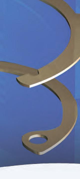


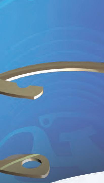


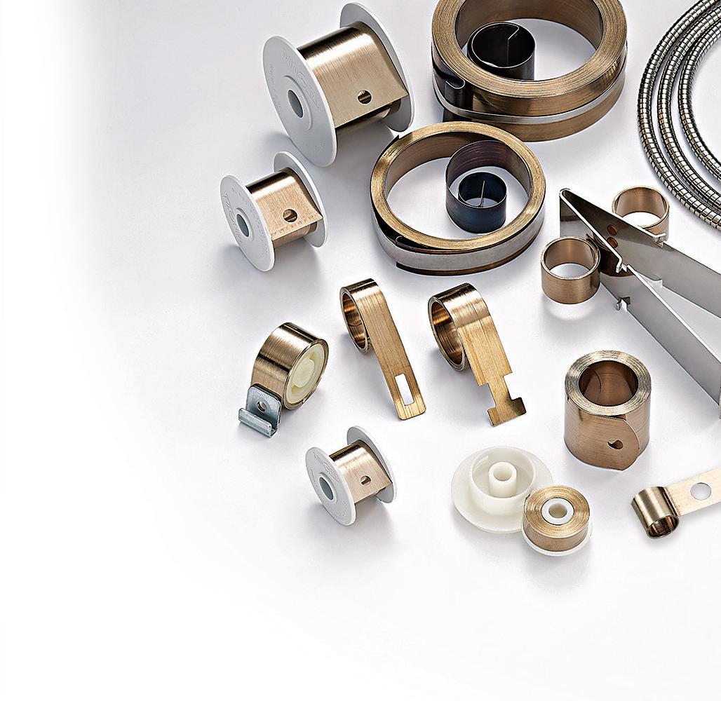
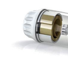
Free Engineering Support: info@rotorclip.com • +1.732.469.7333 Application Driven Solutions Product Focused, Support Driven Every ring, every style, one manufacturer (spiral, tapered, constant ) Diameters from .100" to 140" Readily available in assorted platings and alloys Industry focused engineering Request Samples rotorclip.com Tapered Section Constant Section Spiral Ring Coiled Or Stamped, Engineered for You Over 20,000 Standard Parts TM
The value of good advice
There’s an old proverb that says, “Good advice is beyond all price.” This might be true, but people generally tend to ignore advice, at least the unsolicited kind. For business owners and entrepreneurs, the reason is simple: they’re too busy working. Overwhelm and multi-tasking means there’s little time for heeding new information outside of day-to-day operations.
However, growth is highly dependent on taking innovative steps and integrating new insights — which often come from good advice. A 2021 survey from McKinsey Global Survey found that the more transformation actions a company takes, the greater its chances for success.
It states: “Transformation success relies on a comprehensive approach and is more likely to be achieved when companies take a greater number of actions.” In other words, the more open a company is to learning and incorporating new skills, technologies, and ways of doing business, the more likely it is to last.

Flexibility and innovation are also critical to survival in challenging times, which every business likely experienced over the last few years and may again, given the ongoing supply-chain delays and a potential recession ahead.
Jennifer Sturm, COO of Empire Bolt, writes wisely on page 44, “Successfully working in the fastener industry entails ongoing learning — even for experts in the field.” In business (and life), to stop learning is to halt growth.

It seems seeking out good advice and putting it into practice is often worth the price. In support of this initiative, here are just a few of the nuggets of wisdom found inside the pages of this publication:
“Advanced companies want to work with other well-run organizations,” says Lonni Kie er of SmartCert (page 54). Obvious advice, perhaps, but how many outdated processes does your company still run on? The digital era is here, and digitalization ensures a traceable supply chain, saving time and long-term costs that are better spent on further improving your business.
“The price point also matters,” says Brad Klippstein with Bosch Rexroth. “End users require cost-e ective measures that meet budgets and readily support manufacturing orders.” (Learn more on page 34).
“The fastener industry is interfaced with many di erent sectors, where the right product delivered on time is critical,” shares Rob LaPointe of AIM Testing Laboratory (see page 56). “It’s worth the e ort and expense to ensure that your industry contribution is received without issue.”
So, how does one ensure an e cient and e ective contribution to the fastener industry? Sometimes it takes heeding advice from those companies already earning success and respect. As Christie Jones with SPIROL International writes (page 42): “It’s recommended that manufacturers partner with industry experts in joining and assembling to identify the lowest and best cost solution for their assembly.”
DESIGN WORLD www.fastenerengineering.com December 2022 1
editorial
AdobeStock
EDITORIAL
VP, Editorial Director
Paul J. Heney pheney@wtwhmedia.com @wtwh_paulheney
Managing Editor Mike Santora msantora@wtwhmedia.com @dw_mikesantora
Executive Editor
Leland Teschler lteschler@wtwhmedia.com @dw_leeteschler
Executive Editor Lisa Eitel leitel@wtwhmedia.com @dw_lisaeitel
Senior Editor Miles Budimir mbudimir@wtwhmedia.com @dw_motion
Senior Editor Mary Gannon mgannon@wtwhmedia.com @dw_marygannon
Senior Editor Rachael Pasini rpasini@wtwhmedia.com
Associate Editor Heather Hall hhall@wtwhmedia.com @wtwh_heathhall
Senior Contributing Editor Leslie Langnau llangnau@wtwhmedia.com @dw_3dprinting
CREATIVE SERVICES
VP, Creative Services Mark Rook mrook@wtwhmedia.com @wtwh_graphics
Senior Art Director


Matthew Claney mclaney@wtwhmedia.com @wtwh_designer
Senior Graphic Designer Allison Washko awashko@wtwhmedia.com @wtwh_allison
Graphic Designer Mariel Evans mevans@wtwhmedia.com @wtwh_mariel
Director, Audience Development
Bruce Sprague bsprague@wtwhmedia.com

WEB DEV / DIGITAL OPERATIONS
Web Development Manager B. David Miyares dmiyares@wtwhmedia.com @wtwh_webdave
Senior Digital Media Manager Patrick Curran pcurran@wtwhmedia.com @wtwhseopatrick
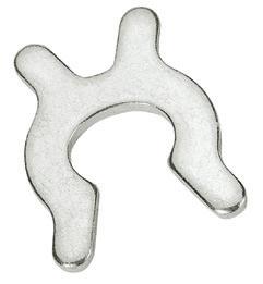
Front End Developer Melissa Annand mannand@wtwhmedia.com
Software Engineer David Bozentka dbozentka@wtwhmedia.com
DIGITAL MARKETING
VP, Digital Marketing Virginia Goulding vgoulding@wtwhmedia.com @wtwh_virginia
Digital Marketing Manager Taylor Meade tmeade@wtwhmedia.com @WTWH_Taylor
Digital Marketing Coordinator Jill Bresnahan jbresnahan@wtwhmedia.com @WTWH_Jill
Webinar Coordinator Halle Sibly hkirsh@wtwhmedia.com
Webinar Coordinator Kim Dorsey kdorsey@wtwhmedia.com

EVENTS


Events Manager Jen Osborne josborne@wtwhmedia.com @wtwh_jen
Events Manager Brittany Belko bbelko@wtwhmedia.com
Event Marketing Specialist Olivia Zemanek ozemanek@wtwhmedia.com
VIDEO SERVICES
Video Manager Bradley Voyten bvoyten@wtwhmedia.com @bv10wtwh
Videographer Garrett McCafferty gmccafferty@wtwhmedia.com
PRODUCTION SERVICES
Customer Service Manager Stephanie Hulett shulett@wtwhmedia.com
Customer Service Representative Tracy Powers tpowers@wtwhmedia.com
Customer Service Representative JoAnn Martin jmartin@wtwhmedia.com
Customer Service Representative Renee Massey-Linston renee@wtwhmedia.com
Customer Service Representative Trinidy Longgood tlonggood@wtwhmedia.com
Digital Production Manager Reggie Hall rhall@wtwhmedia.com
Digital Production Specialist Nicole Johnson njohnson@wtwhmedia.com
Digital Design Manager Samantha King sking@wtwhmedia.com
Marketing Graphic Designer Hannah Bragg hbragg@wtwhmedia.com
Digital Production Specialist Elise Ondak eondak@wtwhmedia.com
FINANCE Controller Brian Korsberg bkorsberg@wtwhmedia.com
Accounts Receivable Specialist Jamila Milton jmilton@wtwhmedia.com
Medical Design & OUTSOURCING
Editor Michelle Froese mfroese@wtwhmedia.com @FastenerEng
WTWH Media, LLC 1111 Superior Ave., Suite 2600 Cleveland, OH 44114 Ph: 888.543.2447 FAX: 888.543.2447


Follow the whole team on twitter @DesignWorld Engineering
Engineering
TOP WORK PLACES 2022 2014 Winner 2011 - 2020 2013 - 2017, 2021 2014 - 2016
2 December 2022 www.fastenerengineering.com DESIGN WORLD

Contents 4 ADHESIVES: Intro Understanding adhesives: What different types are available? 6 ADHESIVES: Formulations What projects require custom adhesive formulations and why? 10 ADHESIVES: Biocompatibility Is your adhesive biocompatible? 12 ADHESIVES: Curing What benefits do UV curable adhesives offer? 16 ADHESIVES: Threadlocker What are the common mistakes and pitfalls when choosing a threadlocker? 20 ASSEMBLY: Fasteners How to keep fasteners from loosening? 22 BOLTING What is the load transfer factor? 26 HARDWARE How advances in latches and hinges are enhancing user experiences 30 INSTALLATION What are the different tightening methods for a screw? 32 MANUFACTURING: Cold Forming What is cold-form manufacturing? 34 MANUFACTURING: Smart Manufacturing What is “smart mechatronics” and how can it support fastener manufacturing? 36 MATERIALS How is lightweighting affecting fastener materials and designs? 12 • 2022 • fastenerengineering.com DESIGN WORLD www.fastenerengineering.com December 2022 3 40 NUTS What are nut retainers? 42 PINS What’s the difference between cold-headed and machined solid pins? 44 QUALITY CONTROL: PLATING What is plating and what causes electroplated coatings to fail? 46 RIVETS How to best choose and install rivet nuts? 50 SCREWS What are the more common screw-head types? 52 SEALS How to choose an O-ring for your application? 54 SUPPLY CHAIN Supply chain issues: How much is lost paperwork costing your company? 56 TESTING Why should you test the fasteners you sell? 58 TOOLS Why are battery-powered tools the preferred choice? 60 TRAINING What are thet answers to some of the most common fastener failures? 62 WASHERS What are the advantages of using hardened and unhardened flat washers? 64 WELDING: Materials What is micro-welding and why is laser an ideal fit? 66 PROFILES 72 AD INDEX AdobeStock AdobeStock AdobeStock
ADHESIVES

Understanding adhesives: What different types are available?

Adhesives are materials capable of fastening or binding two surfaces. Also called glues, sealants, and cement, adhesives work by surface attachment but without altering these surfaces.
An adhesive’s ability to hold fast and bond to a surface is critical. However, those features are not the sole determinant of performance. An ability to bond to dissimilar materials, form crystalline or reliant structures, and bond quickly or slowly are also important considerations.
The good news is there are many adhesives available tailored to several applications. The bad news is there’s no one adhesive ideal for all applications. Knowledge of the attributes and shortcomings of adhesives is required to choose wisely. The final application must also be considered, including the environment or conditions it will be subject to.
Compared to other joining methods — such as mechanical fastening or welding — adhesives can o er several advantages. They
can reduce the time and cost of assembly, improving stress distribution. They can lengthen the working time, allowing for adjustments during assembly. They can also add performance by reducing assembly noise, for example.
Some adhesives are rigid and tough when cured, while others are soft and flexible. Some form permanent bonds, while others o er impermanent bonds that be undone without damage to the substrates. Typically, adhesives are more di cult to disassemble than mechanical fasteners.
The reliability and durability of adhesives continue to improve, but failures still happen. There is no single, universal adhesive. The ideal adhesive choice requires knowledge of the surfaces to be joined. Surface preparation is essential and primers or other surface treatments often maximize bond strengths.

4 December 2022 www.fastenerengineering.com DESIGN WORLD
Adhesives can be classified in several ways, such as reactive or non-reactive. Reactive adhesives require a chemical reaction to form a bond. Non-reactive adhesives require no chemicals but might undergo a physical change during bonding. Examples include hotmelt, pressure-sensitive, and solvent-based adhesives.

Reactive adhesives raise the bar on performance substantially but are nothing new. In fact, some ancient adhesives take advantage of chemical reactions during curing.

Modern reactive adhesives are thermoset polymers, where a chemical reaction is responsible for curing the adhesive. Typically, two components are mixed to start the curing. Some adhesives also rely on reactants, such as water. It’s wise to learn thoroughly about adhesives before selecting a formulation for any application.
DESIGN WORLD www.fastenerengineering.com December 2022 5
AdobeStock
FORMULATIONS
What projects require custom adhesive formulations and why?
Some products, regardless of how big or small, require custom-formulated adhesives. Although formulations vary depending on technicality, the objective is a reliable and costeffective end product that complies with a company’s quality, design, and manufacturing goals.
Scenarios calling for custom adhesives Purchasing an off-the-shelf adhesive as a component for an assembly or mechanical project is a common step in the design process — but sometimes it’s simply not possible.
There are a few reasons why an adhesive with the ideal combination of qualities might not exist for a specific assembly. In such cases, a custom formulation is necessary. This is particularly true in heavy industries where stringent manufacturing requirements and performance are essential.
The following are a few examples where customization is worth considering to ensure reliable manufacturing.
No adhesive matches the project’s needs. If your design specifications call for a specific level of bonding and no off-theshelf adhesive can meet the requirements, your whole production schedule might be in jeopardy. This is common when dealing with precision engineering in aerospace, transit, or defense projects. If no adhesive provides reliable results, it’s time to consider custom formulation.
An off-the-shelf formula is discontinued. What happens when you’ve found an adhesive that works, but it’s removed from production? In such cases, keeping the assembly line moving can be challenging, and it’s time to reach out to a lab that can formulate a new high-quality epoxy, urethane, silicone, or another adhesive type.
It’s possible the custom replacement won’t only match the performance possible with the old formula but also improve upon it.
Existing adhesives fail to comply with regulations. As governmental agencies tighten the restrictions around which chemicals are deemed safe, it’s not uncommon for older substances to be banned. An integral ingredient in your company’s products might be listed for non-compliance. As with discontinued formulations, it’s important to find a lab that can create a custom formulation to replace the lost chemical.
The new formulation must deliver the same performance or better while also complying with the law in question.

6 December 2022 www.fastenerengineering.com DESIGN WORLD
Article courtesy of Gluespec
Types of adhesives (according to Adhesives.org)
Between off-the-shelf options and new formulations, acquiring an adhesive that fits just about any description or requirement is possible. To better understand why certain products require custom adhesive formulations, it’s necessary to delve into the types of adhesives and what they’re used for.
An adhesive is a non-metallic binder that acts via adhesion and cohesion. The classification of adhesives depends on their:
• Form (paste, liquid, etc.)
• Chemistry (polyimides, epoxies, etc.)
• Type (hot melt, contact, etc.)
• Load-carrying capability (structural or non-structural)
When deciding on an adhesive for an application, manufacturers consider the tensile and shear strength, dimensional stability, temperature resistance, and compatibility of materials.
Structural adhesives are strong, known as load bearing, and are useful for engineering applications. Consisting of epoxies, cyanoacrylates, and some acrylic adhesives, these products can undergo shock, vibration, and other destructive agents and remain bonded.

Pressure-sensitive adhesives are typically purchased as tapes or labels and do not solidify to form a solid material. Bonds are formed by bringing the adhesive film in contact with the substrate and applying pressure. Pressure-sensitive adhesives are typically used to temporarily hold objects in place during assembly.
Thermosetting structural adhesives are typically available in two-part forms and are mixed carefully within a limited time window. They usually have a “pot
DESIGN WORLD www.fastenerengineering.com December 2022 7
AdobeStock
FORMULATIONS
life,” which is the amount of time the adhesive is workable once mixed and able to make a satisfactory bond.
Reactive versus non-reactive Reactive adhesives can be characterized by the formation of permanent bonds between substrates that create resistance against chemicals, moisture, and heat (think structural adhesives). Typically, a reactive adhesive is made of a monomer (resin) and an initiator. Due to the chemical bond, reactive adhesives have long-term durability and high bond strength.
When choosing an adhesive, it’s essential to consider what the product will need to endure. For example, reactive adhesives cure to form a material, as opposed to solvent or hot-melt adhesives. This means reactive adhesives are more durable against the effects of extreme temperature and general environmental resistance.
Epoxies are one of the most used structural adhesives due to their range of forms, high-tensile strength, dimensional stability, and ability to adhere to several materials. They can be room-temperature or heat-cured (depending on the additives). Advances in additives and formulation have made epoxies more resistant to chemicals.
A reactive two-part adhesive works as follows: base resin + hardener/curing agent → plastic or rubber
It transforms into a thermoset polymer via a cross-linking process. For a reactive one-part adhesive, UV light, heat, or moisture is required (it’s a pre-mixed, two-part adhesive, but the reaction requires light, heat, or moisture to begin). Other reactive adhesives include acrylic, silicone, urethane, and cyanoacrylate (super glue).
Non-reactive adhesives do not have a permanent chemical bond, but bond through a physical change. Examples include polyvinyl acetate, construction adhesive, hot glue, and contact adhesive.
An emulsion adhesive works as follows: adhesive + evaporative solvent → solvent evaporates
As the solvent evaporates, it leaves the adhesive behind.
Natural versus synthetics
Another categorization of the many forms of adhesives is if they’re natural or synthetic. Historically, adhesives were made of naturally occurring components, but now it’s common to find a combination of natural and synthetic compounds.
Natural adhesives are made from natural materials, like animal and plant matter, and occasionally, minerals. Animal-based adhesives are made from albumin, beeswax, casein, and gelatin. Plant-based adhesives are made from components like dextrin, natural resins (gum arabic, balsam), oils, waxes, soybean protein, and starch. Mineral-based adhesives come from components of amber, paraffin, silicates, and sulfur.
While these types of adhesives are generally affordable to manufacture and are still used for wood, paper, film, and foil materials, most adhesives employed today belong to the newer synthetics category. Synthetic adhesives are developed from human-made polymers.
Although more costly than natural adhesives, synthetic alternatives are customizable and feature greater bond strengths.
To learn more, visit https://tinyurl.com/GlueSpec

AdobeStock 8 December 2022 www.fastenerengineering.com DESIGN WORLD


biocompatibility
Is your adhesive biocompatible?
Evanoski, Group Product Manager Global Business Development, Dymax
Biocompatibility is a general term
to describe that a material’s property is compatible with living tissue or living system. Non-toxic, injurious, or physiologically reactive materials to the body or bodily fluids are considered biocompatible and are often sought by medical device engineers.
In simple words, biocompatibility tests are not used to prove chemical compatibility but to confirm a lack of immune reaction to the material or device.
Choosing the ideal material during the design process gives manufacturers more confidence in an FDA (Food and Drug Administration), MDR (medical device regulation), or other device approval.
Biological reactivity testing is one such process used for determining suitability and safety. Two main tests indicate if the material is biocompatible or not.
USP Class VI biocompatibility testing
Historically, standards were set by the US Pharma Convention (USP), a non-profit organization focused on medications, healthcare technologies, food ingredients, and materials used in medical devices. These standards categorize materials into six classes depending on the product’s specific use and duration of patient contact time (limited, prolonged, or permanent). Class VI is the most rigorous. It includes three reactivity assessments typically performed in vivo on mice or rabbits to ensure accuracy.
1. Acute systemic toxicity (systematic injection) test: Measures toxicity and irritation when a compound sample is administered orally, applied to the skin, and inhaled.
2. Intracutaneous test: Measures toxicity and localized irritation when the sample is in contact with live subdermal tissue (specifically, the tissue that the medical device intends to contact).
3. Implantation test: Measures toxicity, infection, and irritation of the intramuscular implantation of the compound into a test animal over several days.
10 December 2022 www.fastenerengineering.com DESIGN WORLD
Michelle
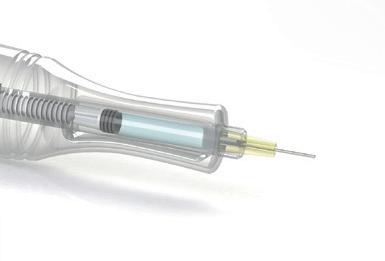
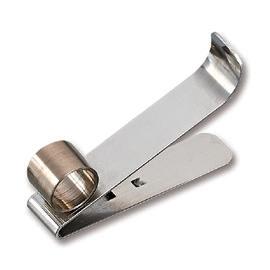
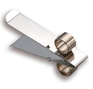
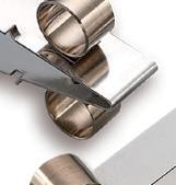
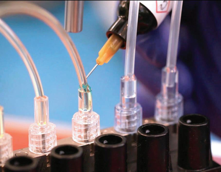
Medical device adhesives must meet various biocompatibility approvals before being released into the market.
A lab tech applies adhesive to a tube set assembly to prepare it for physical property testing.
Although Class VI is typically used to evaluate plastic materials that may be in contact with injectable medications or other fluids, adhesives and sealants that qualify for this designation are generally highly safe for medical devices. However, materials passing the USP class VI tests are not guaranteed to be biocompatible for every application. It’s simply a strong validation that the materials meet low toxicity requirements usually associated with pharmaceutical tubing, fittings, systems, and parts.
ISO 10993 biocompatibility testing
To standardize the biological evaluation of medical devices globally, the International Standards Organization (ISO) developed ISO 10993 — a set of standards outlining material categories, tests, and test methods used to determine the biocompatibility of materials.
The ISO strategy categorizes medical devices by type of body contact (surface device, external communication device, and implant device) and by contact duration (limited, prolonged, and permanent). The ISO provides a set of suggested evaluation tests for each medical device category.
Typical tests include:
• ISO 10993-4 Hemolysis
• ISO 10993-5 Cytotoxicity
• ISO 10993-6 Implantation 14 Days
• ISO 10993-10 Intracutaneous: Sensitization and Irritation*
• ISO 10993-11 Systemic Toxicity
* Note: as of 2021, ISO 10993-10 now contains a description of skin sensitization testing only (Part 10: Tests for Skin Sensitization), and the testing for Irritation is now described in Part 23: Tests for Irritation
In general, adhesives and sealants are not required to pass all ISO tests. However, to be considered of medical grade, it’s expected they pass the cytotoxicity.
As a fast, standardized, sensitive, and inexpensive test, the cytotoxicity test concludes if an adhesive has any adverse effect on mammalian cells. It involves culturing cells in vitro and systematically exposing them to the material in question to see if any reactions or signs of toxicity show up over a few days.
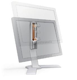
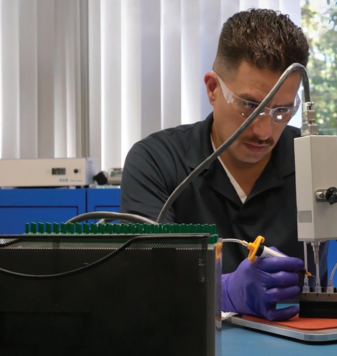
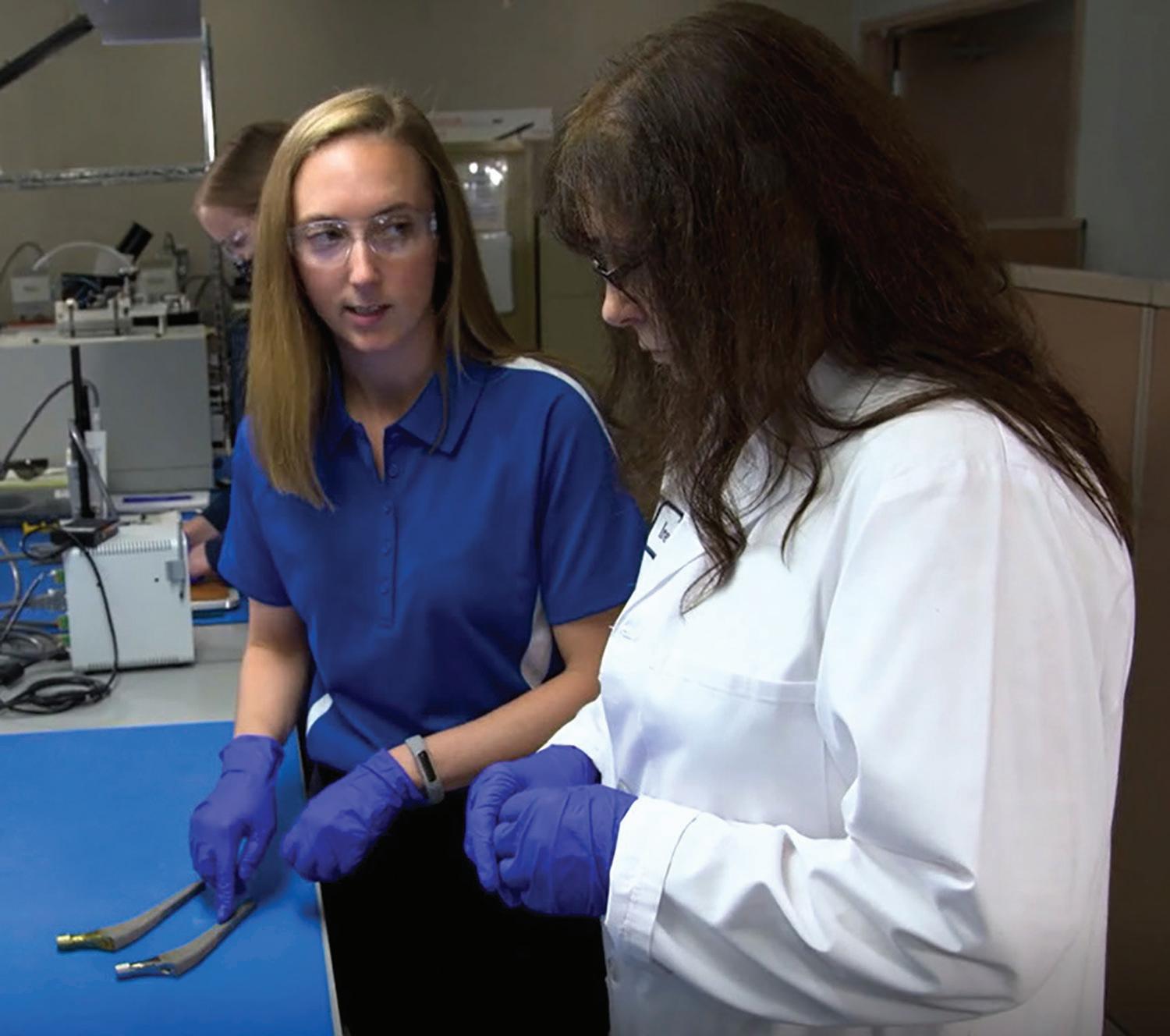
Application engineers discuss using a maskant with ISO 10993-5 cytotoxicity approval on an orthopedic implant.
Since the ISO system applies the USP test methods as part of a larger, more rigorous strategy, meeting ISO standards represents a higher level of biocompatibility than meeting USP Class VI standards.
DESIGN WORLD www.fastenerengineering.com December 2022 11
What benefits do UV curable adhesives offer?
UV curable adhesives offer 100% solid material, near-instant curing times, and immediate use or packaging directly from the assembly line. While significant, these features can only be fully appreciated compared to alternative curing methods.
For example, compare the 100% solid material with low-viscosity solvent-based coatings. Only 5% might remain after the solvent has completely evaporated. Up to 95% of the chemical solvent is off-gassed into the air.
As a result, the Environmental Protection Agency has prioritized reducing solvent-based materials. U.S. manufacturing has also shifted away from these adhesives to decrease the volatile organic compounds created when the solvent evaporates.
With up to 95% material loss, 100% solid materials such as UV-curable products typically offer more savings than solvent-based products. Consider a company purchasing 1,000 gallons of low-viscosity solvent-based materials. With a material that’s 5% solid, they’ll receive 50 gallons of solid material.
• 1,000 gallons * 0.05 solid material = 50 gallons yield of residual material to coat or adhere
If the solvent-based adhesive costs $80 per gallon, the invoice will be $80,000.00. When evaluated after evaporation, the cost is higher.
• $80,000 / 50 gallons = $1,600 per solid gallon
If the 100% solid material costs 10 times as much ($800 per gallon), the material gets the same 50 gallons of coverage.
• $800 * 50 gallons = $40,000
• $80,000 cost for solvent materials – $40,000 cost for solid materials = $40,000 in savings
• The user saves 50% or $40,000
12 December 2022 www.fastenerengineering.com DESIGN WORLD
curing
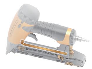
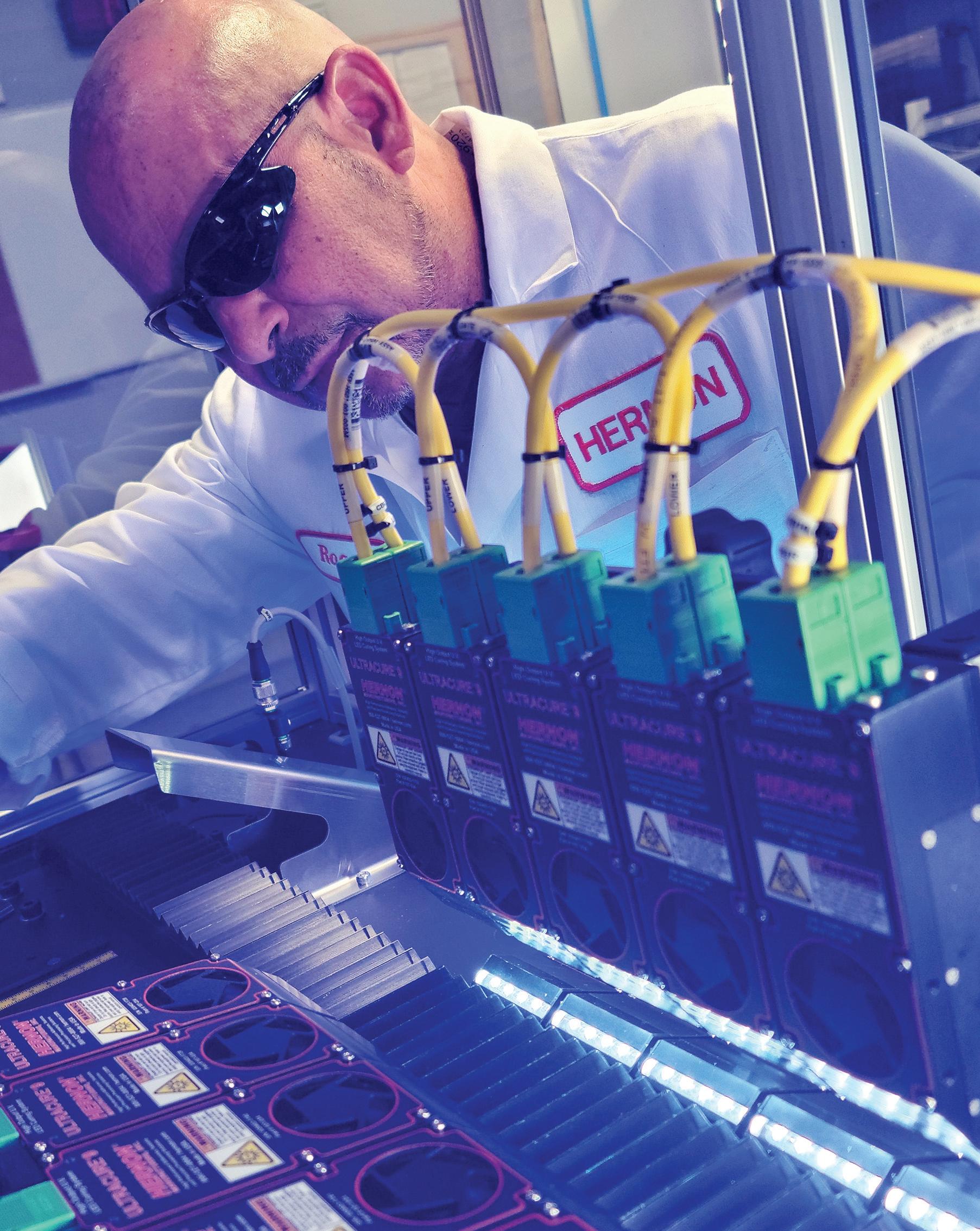
Drew Richards, Marketing & Customer Experience Manager, Hernon
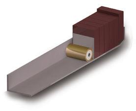
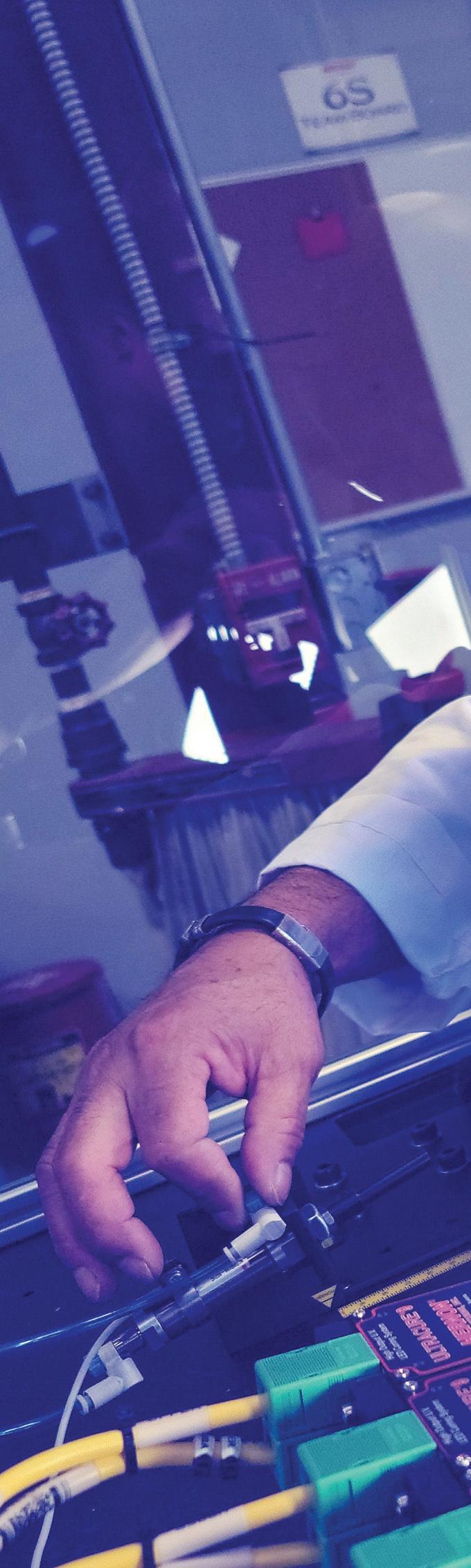
A technician places a part-ejection piston to remove ammunition cartridges that fail to meet a specified customer standard. When paired with machine-vision inspection, this quality-control measure allows customers to fine-tune machine settings so no unsealed parts proceed to the next production stage.
The savings continue. The user who switches saves logistically by transporting 50 instead of 1,000 gallons. The cost of filters for solvent-based material in the dispensing system and the labor are removed.
Most applications also require time to let the solvent evaporate. This necessitates a batch process and often includes a large amount of floor space for the drying racks. Sometimes heat is used to reduce the drying time, so switching also saves oven and energy costs and maintenance. The emission removal process and equipment (and
any associated EPA penalties) are removed.
The UV advantage
Photo-initiators in the adhesive formula must be triggered by a UV light of the correct wavelength to activate UV-cure products. For consistent results, the intensity of the light must be uniform and penetrate the adhesive materials to ensure sub-surface curing. There’s a science to distributing UV lights to ensure optimal conditions.
LED lights create spherical radiance zones, which must overlap and ensure
consistent coverage. Getting too close or intense with the UV light leads to bubbling or burning in the adhesive material, requiring a goldilocks approach to each application. If more distance is needed, the UVs can be modified with a lens to focus the light into a concentrated beam. This extends the practical curing distance and improves efficiency.
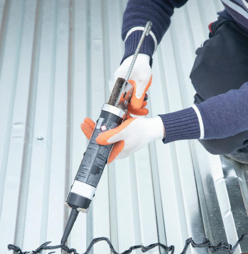
For ammunition sealants, the sealant is exposed in a small area around the cartridge case mouth and primer, so focusing the light with a lens is useful. Six to seven seconds of UV exposure is
DESIGN WORLD www.fastenerengineering.com December 2022 13
curing
required that’s set up in an array along the conveyor route, about 1.5 inches from the exposed sealant. The array’s length depends on the speed of the conveyor — the faster it is, the longer the array should be to ensure the correct exposure time.
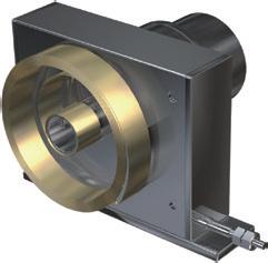
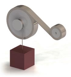
Photo-initiators can also be used in multi-cure formulas to address specific manufacturing challenges. For example, in some electric motor manufacturing operations, an adhesive can bond magnets to the motor housing. The specifications call for enough material to create some squeeze-out.
Using a multi-cure formula, the adhesive under the magnet can be activated and cured using a pre-applied chemical activator or anaerobic curing process. The squeeze-out material can be rendered inert by hitting it with UV light. The near-instant speed of the UV cure process makes it ideal for this process, solving the problem with minimal time delay.
UV tacking
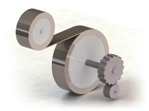
The high speed of UV curing allows for UV tacking, which is when the material is briefly exposed to UV light to alter the physical properties without full curing. UV tacking is employed for sealant dispensed as a bead around the outer diameter of a circular oil shaft seal.
For instance, one manufacturer had problems when a robotic arm moved parts from the dispensing station
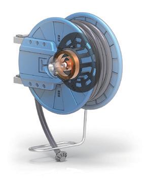
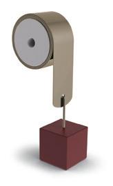
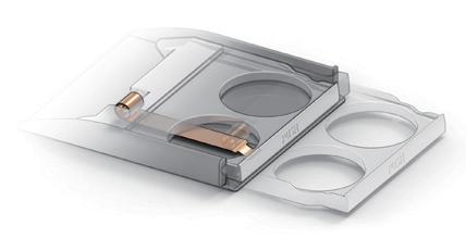
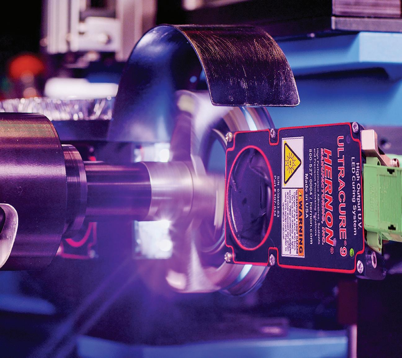
A UV LED curing light is used to test the curing time for a material sealing the bottom of a reservoir flange seal.
to the curing station. The force of the movement caused deformation and migration of the bead. The dispensing station had to be cleared to make room for the next part, so completely curing the bead in the same station did not work.
By UV tacking, the cure material (UV FOG, in this case) was fixed in place with only a second or two of UV exposure. The tacking raised the bead viscosity so it would not deform or migrate when transferred to the next station. Tacking represents the unique ability of UV materials to cure to a set amount. The degree to which the material is cured can be directly controlled and manipulated through the control of UV light exposure. This allows materials to be cured to tacky or partially solid states. Until the material is exposed to UV light, there’s an indefinite working life, allowing an operator to make fine adjustments. Although the UV curing process typically costs more to implement with a conveyor and UV light arrays, this is partially offset by a simpler dispensing system. Most UV cure materials are one-part materials, with the role of the second part (the activator) played by UV light. This means the dispensing system follows a single track with one reservoir, meter, and valve. There’s no need for ratio controls or static mixers and little chance of the material curing in the system. These benefits make UV curing an excellent choice for countless industries. The transition from solvent-based adhesives to UV and other curing methods makes this industry likely to grow as manufacturing technologies upscale.
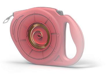
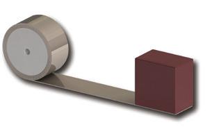
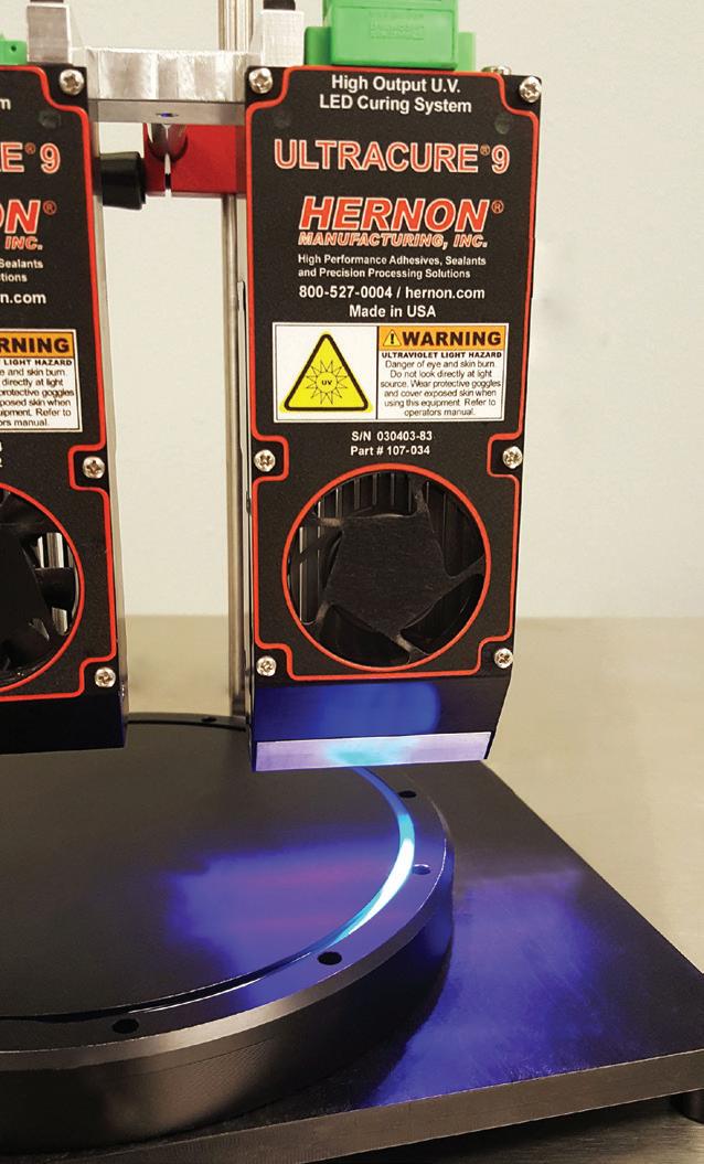
UV FOG sealant from Hernon is cured in place as a bead on an oil shaft seal. The process takes only a few seconds, and the part is immediately ready for handling, packing, and use.
14 December 2022 www.fastenerengineering.com DESIGN WORLD
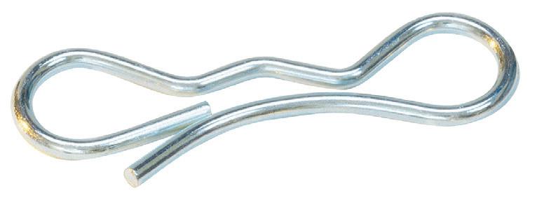
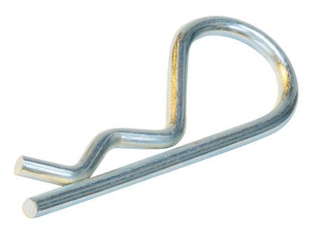
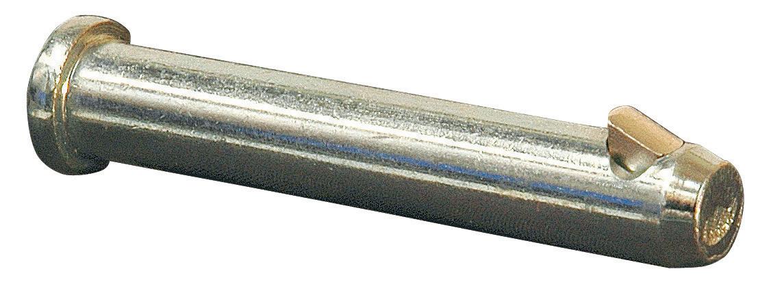
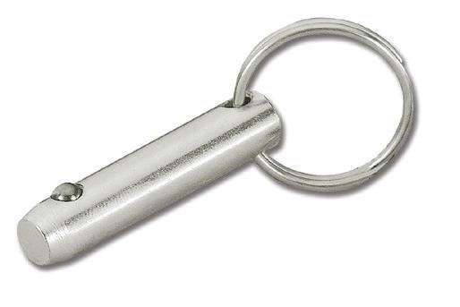
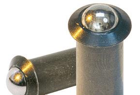
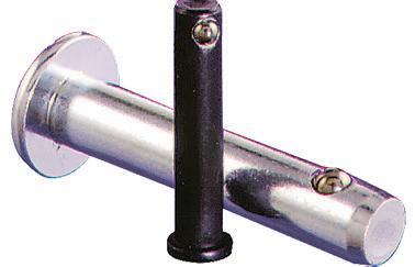
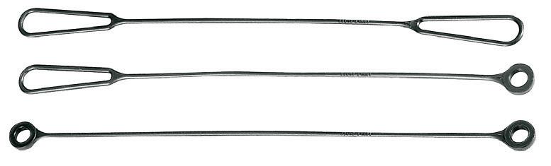
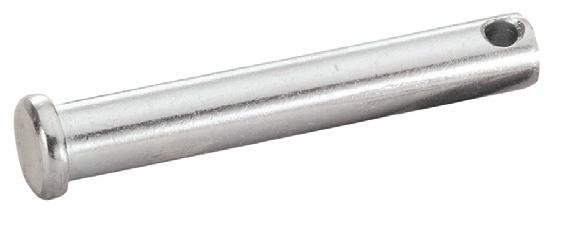
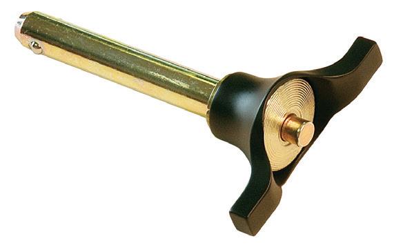

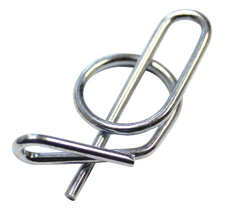


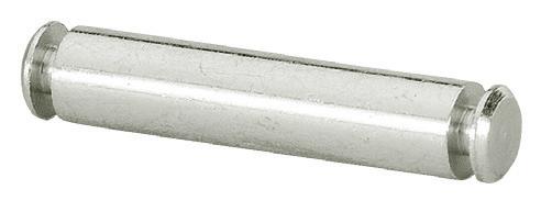


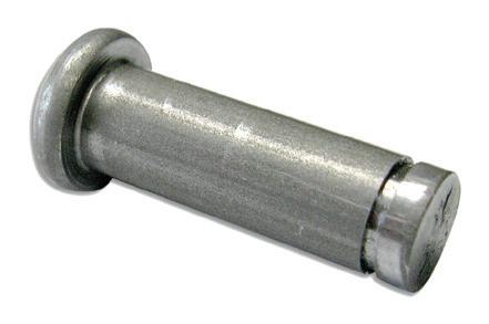
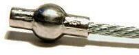
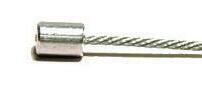
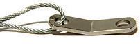
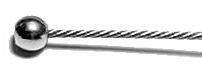
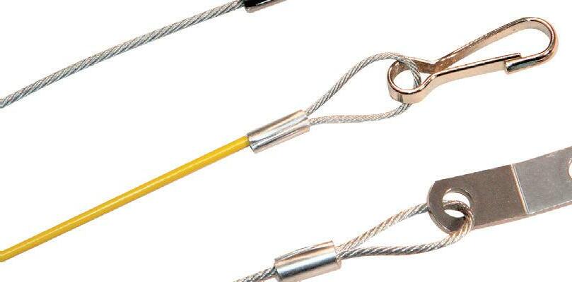

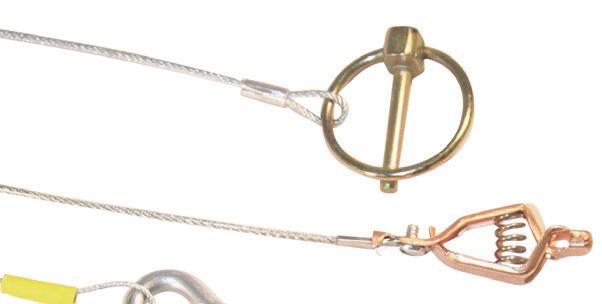
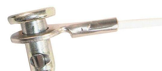

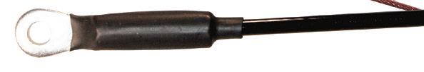
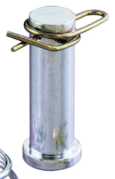
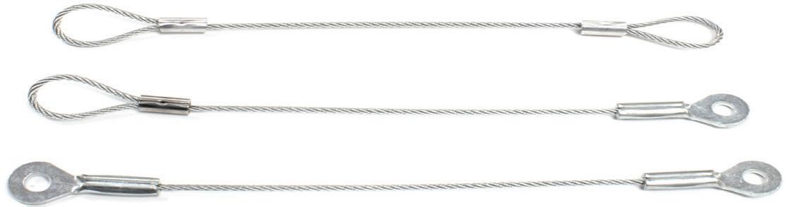
761 Industrial Lane P.O. Box 488 Hustisford, WI 53034 (800) 222-2231 mail@pivotpins.com U.S. Patent No. 6,872,039 & 7,147,420 • Proven and Popular • Pin and Cotter All-In-One • Speeds Assembly Time • Strong, Safe, Fast Nylon Injection Molded! An Inexpensive Light-Duty Tether • Stock and Custom • Free Samples • Fastener Training Sessions (Digital or On-Site) • Free Engineering Assistance • ISO 9001:2015 pivotpins.com PINS / COTTERS SLIC PINS™ QUICK-RELEASE PINS AND MORE... CABLES, LANYARDS & TETHERS DESIGNERS & MANUFACTURERS OF NON-THREADED FASTENING SOLUTIONS
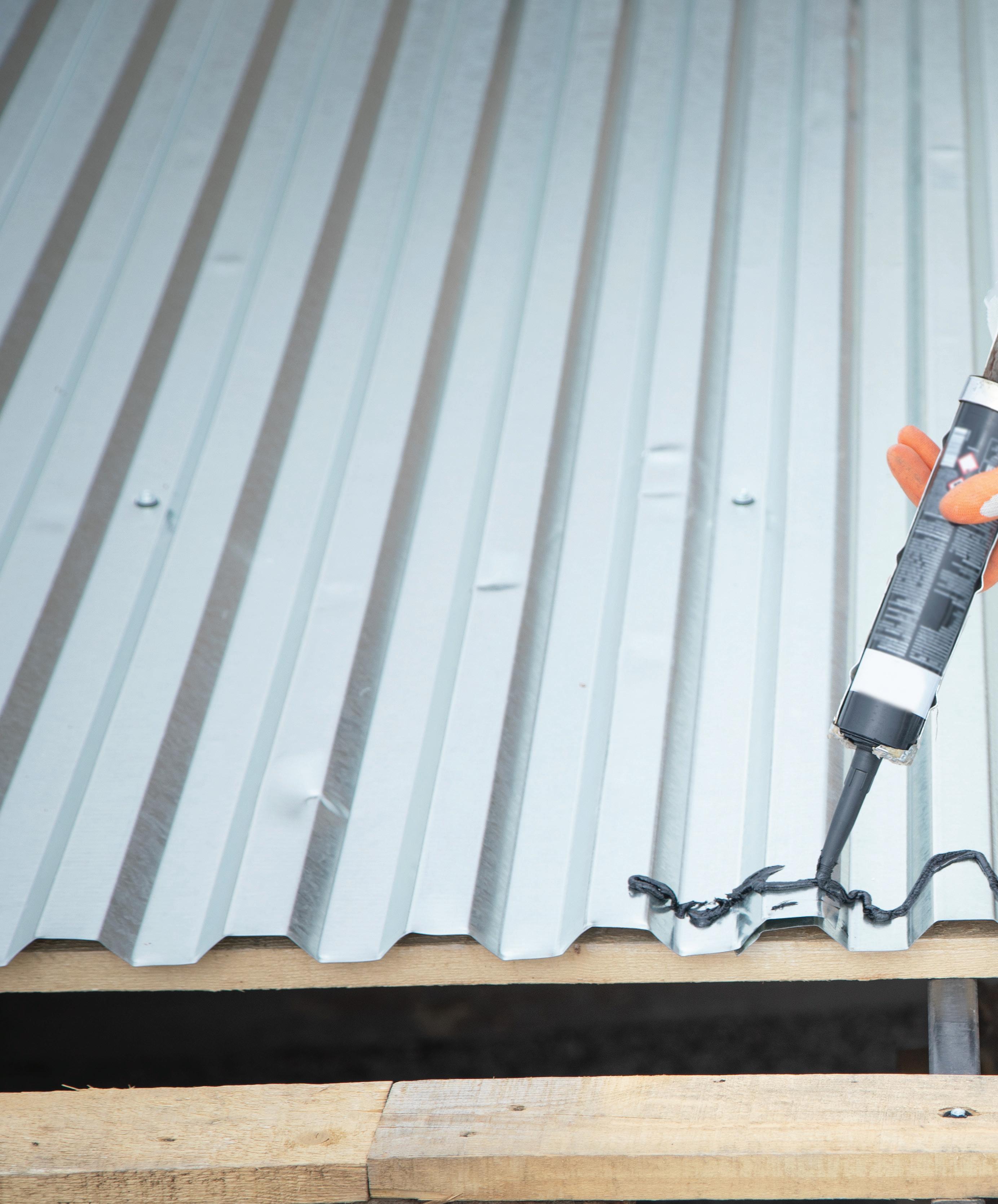
threadlocker
What are the common mistakes and pitfalls when choosing a threadlocker?

To bond any two surfaces, the right tool for the task is vital. This is particularly true when working with threaded assemblies. These types of fasteners can experience challenging service conditions. Subject to vibrations, environmental extremes, torsion, bending, and shocks, they can be susceptible to loosening and leaks.
Choosing the ideal adhesive for an application ensures assemblies stay locked in place. But there’s more to finding success in locking threaded assemblies than choosing the right threadlocker. Proper application and use are also important to ensure performance.
Threadlocking pitfalls
The improper use of a threadlocker can impact its strength and performance. Before applying any type of threadlocker, take the time to understand:
• The properties of the threadlocker
• Where to apply the threadlocker
• The best practice(s) for the application
Failure to understand the why, what, and how can lead to some of the most common threadlocking mistakes.
Making the wrong choice
Threadlockers are typically graded by strength, operating temperature range, and maximum thread size. The most common mistake is to assume the most powerful threadlocker will always do the job, securing bonds as tightly as possible.
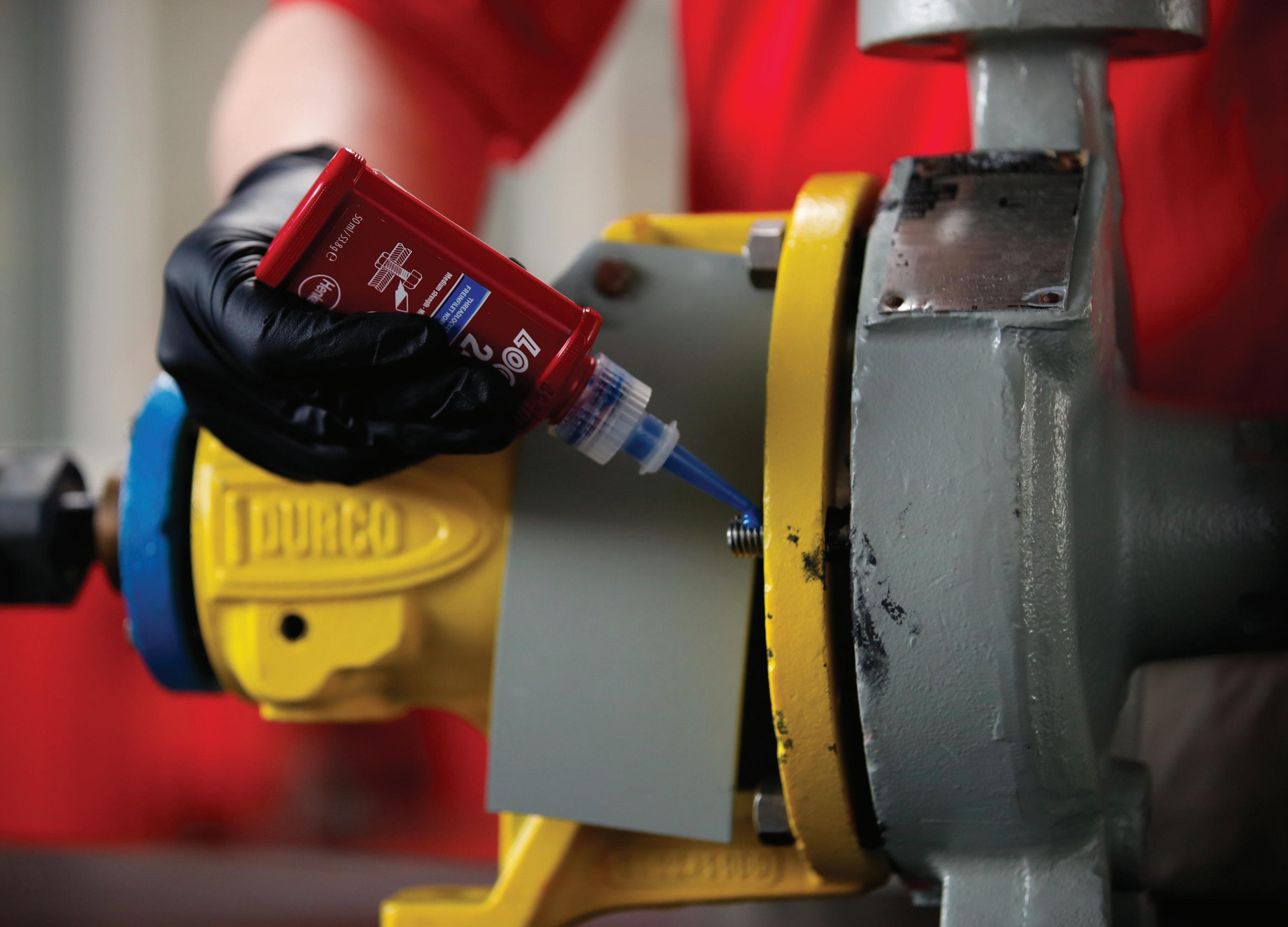
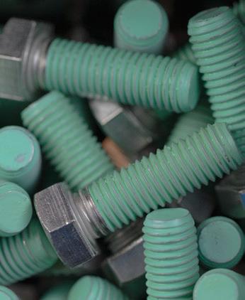
In reality, red threadlockers (labeled for high strength) are commonly deployed in the strongest, most permanent applications. These include heavy equipment, suspension, and bearing cap bolts.
16 December 2022 www.fastenerengineering.com DESIGN WORLD
Article courtesy of Henkel LOCTITE
Deploying red threadlockers as general-purpose adhesives can cause issues, especially if a part needs future disassembly. Red threadlockers often require heat for removal, which can damage some assemblies.
Understanding the difference between threadlocker colors ensures the ideal product is chosen for the job. For example, purple threadlocker is ideal for low-strength and blue is best for medium-strength assemblies.
Applying too much adhesive
If you’ve never used threadlocker, it’s easy to err on the side of caution and apply a lot of the product to ensure a strong bond. You might assume this would improve the assembly’s reliability.
The truth is that more adhesive does not automatically equate to greater strength.
Threadlockers are designed to fill small gaps in threads, so a little adhesive goes a long way. Overuse may cause the adhesive to spread beyond the required surfaces.
Also, any threadlocker outside of the curing area (where the air is present) will remain liquid and not cure. In this case, it’s easy to think the threadlocker failed because it looks like the product is not drying properly, even after the 24-hour curing period.
To create an effective bond, you only need to apply a minimal amount of threadlocker to the area where the
It’s important to ensure the correct threadlocker for each application. For example, LOCTITE Red Threadlocker offers the highest strength of adhesive. Only use red threadlocker for heavy equipment or industrial applications that require an extremely strong hold.
DESIGN WORLD www.fastenerengineering.com December 2022 17
threadlocker
bond will be secured. The same holds true when using a low-strength product — a small amount will provide the strength required.
Lack of preparation
Quality threadlockers are designed to perform in the presence of oil and other contaminants. But that does not mean you should ignore these when applying your adhesives. Preparation is vital.
Before applying threadlocker to a new surface, it’s important to first clean the surface to avoid contaminants. Applying threadlocker to a dirty surface can prevent proper curing by affecting the chemical performance.
Any grease, dirt, or oil present in the assembly can also affect the application and slow the curing process. This can lead to a poor bond, which prevents the threadlocker from meeting its full holding potential.
Not heeding the cure time
Every threadlocker has a specific curing time, detailed within its technical data sheet (TDS), which should be adhered to. Curing refers to the time it takes for the threadlocker to achieve its maximum strength and optimal performance.
Threadlocker curing time is different from fixture time. Fixture time is the point where the assembly has a certain level of handling strength. Many confuse the two. Fixture
time can be as little as a few minutes with some products. But strength can still be gained after this point, so allow for the full cure to avoid assembly failures.
If you try to shorten the threadlocker cure time or use the assembly beforehand, the fastener might loosen.
Repositioning the assembly
One common misconception is to think it’s safe to reposition an assembly after the threadlocker has been applied because it has not cured yet. However, repositioning a bond after it’s been locked in place can lead to threadlocker failure.
As soon as the thread is tightened, the absence of air starts an anaerobic reaction in the adhesive. If you rotate the fastener during this time, you’ll disturb and break the chemical bonds, which will not reform again — even after the bolt has been tightened. This means your threadlocker will never achieve its full strength and adhesion, reducing its ability to perform.
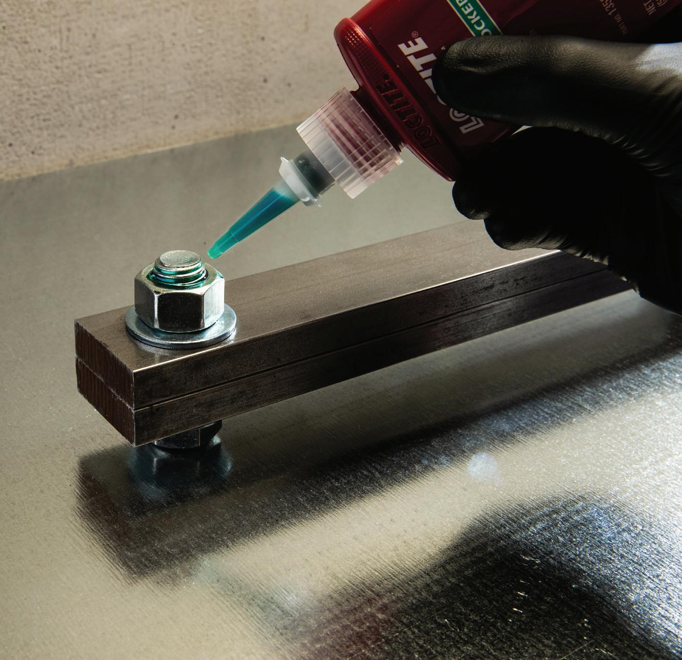
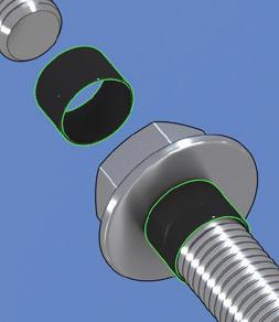
If repositioning the fastener is required before or after curing, you’ll need to remove the existing threadlocker, clean the surfaces, and apply a new one. Where the application allows, you may apply a wicking-grade threadlocker once the assembly position has been set. Wicking grades are typically green and help penetrate preassembled fasteners.
18 December 2022 www.fastenerengineering.com DESIGN WORLD
LOCTITE green threadlocker is recommended for locking preassembled fasteners, preventing against loosening, rust, and corrosion. This wicking-grade threadlocker is categorized as a medium-to-highstrength adhesive.


RIGHT NOW. THE RIGHT STAMPING. THE RIGHT WASHER. REQUEST YOUR FREE 2023 CATALOG & CALENDAR bokers.com (800) -WASH ERS BOKER’S WILL BE THERE. For over 100 years, nearly every industry across the globe has trusted Boker’s to provide quality components, world-class service and on-time delivery.
ASSEMBLY: fasteners
How to keep fasteners from loosening?


Ensuring fasteners remain tightly sealed in applications prone to vibration is a question engineers frequently attempt to solve. Eventually, vibration loosens fasteners by creating relative motion between the threads. This occurs to all nuts and bolts subject to movement, no matter how well you tighten them.
Loose fasteners are certainly a maintenance nuisance but also a hazard in several applications, including in power generation, transportation, manufacturing, and others. The result can lead to accelerated wear, damaged parts, reduced equipment longevity, and safety concerns.

Adequate torque is an obvious first step to ensuring fasteners are properly installed. Using washers to lengthen the ratio of clamped length is another option for certain applications. The washer can add extra friction to the joint and maintain the clamping force.

Vibration-proof fasteners o er another alternative. These are fasteners specifically designed to cope with small movements and vibrations typical of some applications.
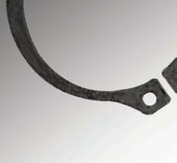
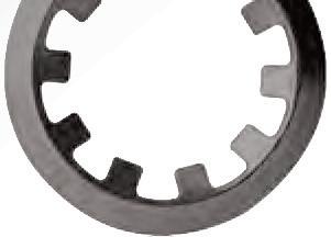
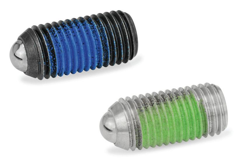
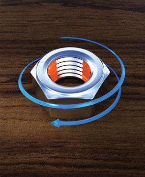
Understanding vibration-proof fasteners Quality counts. Some fasteners are better designed to cope with vibration than others. For example, vibration-proof fasteners are engineered to prevent self-loosening due to vibration. These include hex nuts with nylon inserts, jam nuts, lock nuts, slotted hex nuts, tooth lock washers, lock washers, and spring washers. Such fasteners may have a unique thread design that distributes stress more evenly or an extra clamping system that reduces rotation.
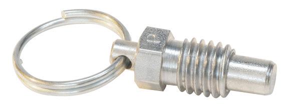
There are also spring plungers with a nylon locking element that are ideal for applications with limited space. They use a spring force to apply pressure, so the ball or nose remains positioned or locked. PFB (Polyamide) patch types are a threadjamming material that also provides some anti-vibration properties that can hold ball plungers in place.


Vibration-proof fasteners are a must for certain applications, such as those subject to heavy vibration and challenging conditions. These types of fasteners are better able to handle movement and prevent self-loosening for added security.
20 December 2022 www.fastenerengineering.com DESIGN WORLD
Article courtesy of JW Winco
AdobeStock
Unfortunately, there is no failsafe solution. The e cacy of vibrationproof fasteners will depend on the application, so maintenance checks are essential.
Tips for choosing vibration-proof fasteners
• Consider the application. What environmental factors must it withstand? What amount of stress is typically placed on the fasteners?
• Is heat a factor? High temperatures are commonly used in critical industries, such as the energy, aerospace, automotive,semiconductor sectors, and others. Specialty fasteners that can withstand harsh conditions (and vibration) are required in these industries.


• Know the shear strength and the ability of the fastener to withstand lateral force without breaking.
• Ensure regular maintenance and repairs. Is there a need for disassembly? If so, you’ll want to consider low to medium-strength fasteners, which require hand tools. Higher-strength fasteners typically need the application of heat for disassembly. Either way, regular maintenance checks are critical in high-vibration or harsh conditions.
• Thread size makes a di erence. Smaller thread sizes make it more challenging to remove fasteners, whereas larger thread sizes typically reduce the e ectiveness of the bond. Know the needs of your application to make the wisest choice. Also,
The PFB patch is a jamming thread-locking material (Polyamide), which provides anti-vibration properties that hold ball plungers in place.
DESIGN WORLD www.fastenerengineering.com December 2022 21 630 800 6377 / Sales@SetkoFas teners com
work with a quality manufacturer or supplier who can make the ideal recommendations for your project.
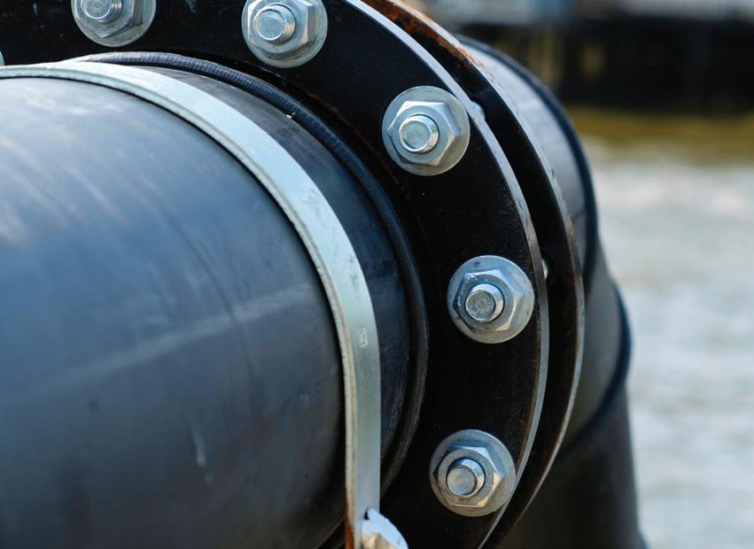
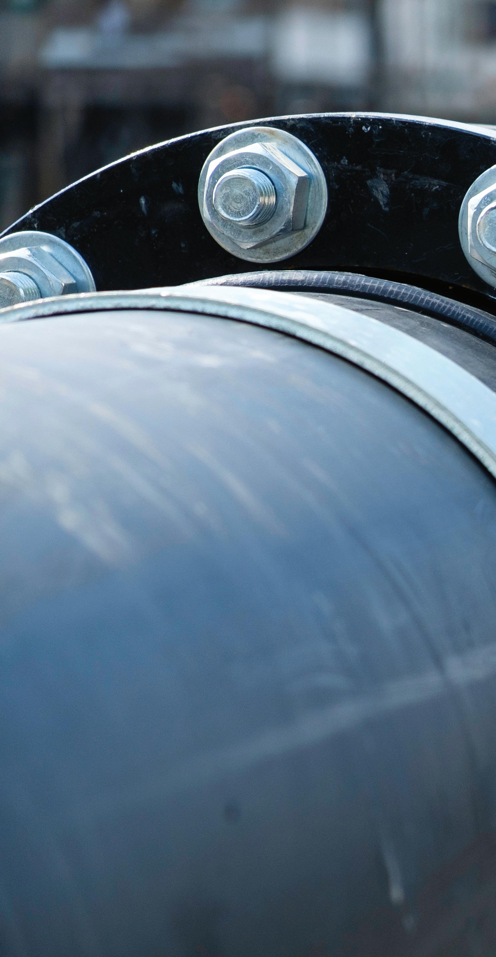
BOLTS
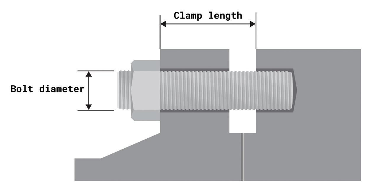
What is the load transfer factor?
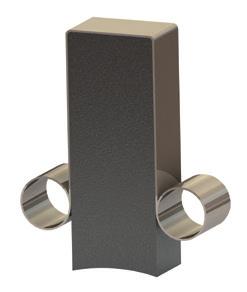
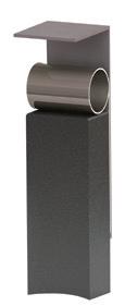
When using hydraulic bolt tensioners to induce a controlled preload into a bolted joint, several key factors including the load transfer factor need to be examined. This is key in ensuring the selected tooling can provide a load greater than the required preload of the joint to overcome any potential losses.
The load can be lost in a joint due to several factors, including:
• Localized yielding
• Joint deformation
• An imbalance in geometry
It can, however, be observed that the difference in stiffness between the joint structure and the bolt can have an effect on the overall load loss in the joint. Load loss in a joint can be theoretically calculated using varying formulas, primarily based on the known data of the bolt diameter and clamp length.
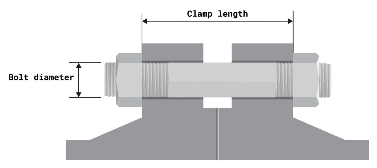
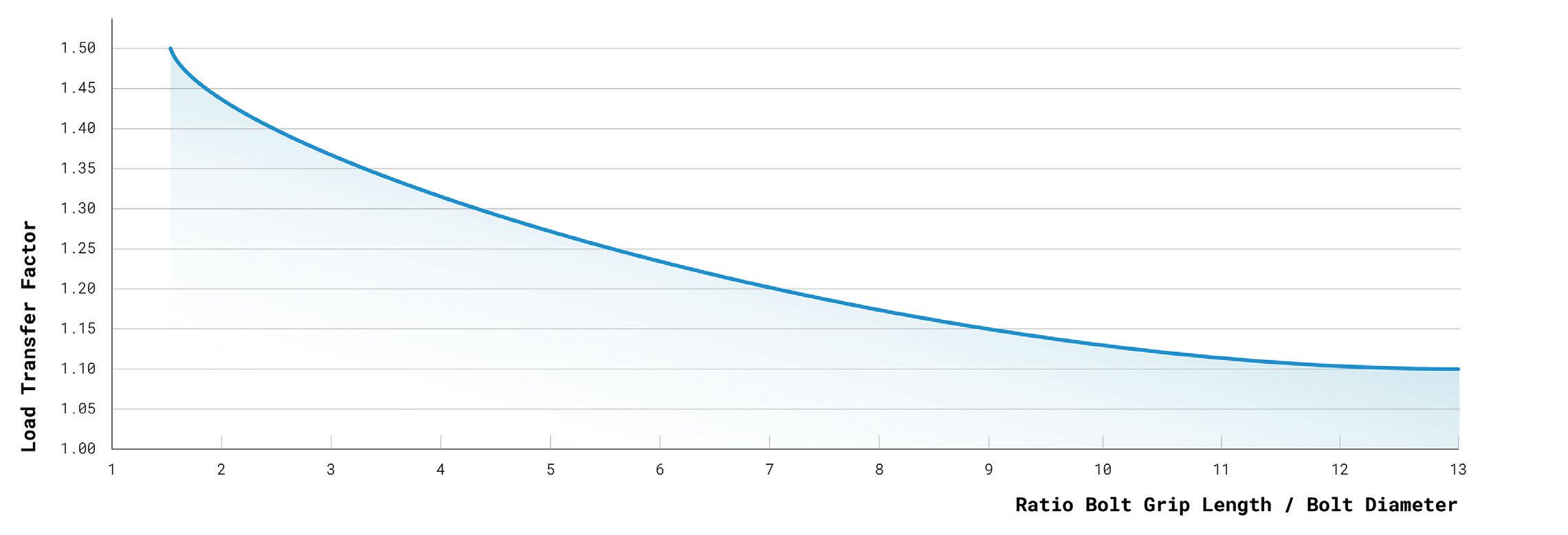
The resultant value of these calculations is commonly known as the load transfer factor (LTF). The LFT gives a theoretical ratio
that can be multiplied against the required preload to generate an applied load, which overcomes the theoretical losses.
Applied load = Preload x LTF
The LTF is important in tool design and tool selection. The maximum output force of the tooling must, at a minimum, match the applied load — but it often exceeds this value.
Careful consideration of the stresses in the joint and bolt is required to ensure loading conditions do not exceed accepted design criteria. In addition, performing the LTF calculation can highlight the need for changes in the loading conditions, joint design, and tensioner design solution.
It’s important to remember that the load transfer factor is a theoretical value and cannot be used to determine the precise load lost within a bolted
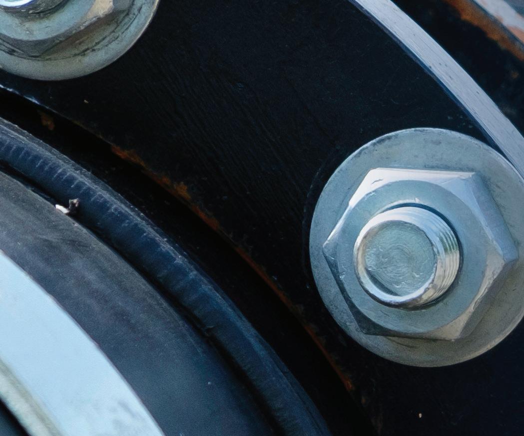
LEFT RIGHT
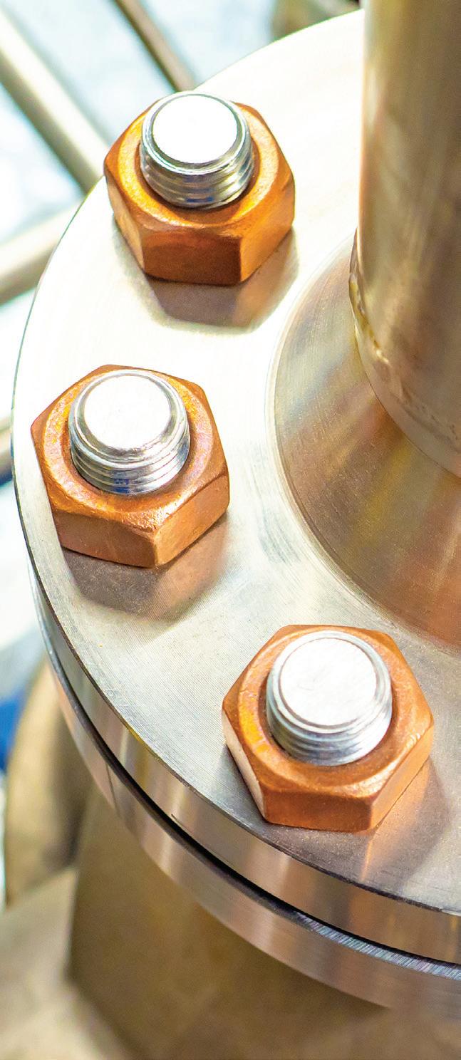
When using hydraulic bolt tensioners, it’s important to ensure the selected tool is capable of providing a load greater than the required preload of the joint.
22 December 2022 www.fastenerengineering.com DESIGN WORLD
Article and images courtesy of Nord-Lock Group
joint. However, for design and load application, LTF provides loading conditions, which allow for the physical losses within the joint.
For accurate load measurement, systems such as bolt elongation measurement via dial indicators or ultrasonic measurements can be used.
Optimizing bolted joints
To optimize a bolted joint, it’s recommended to design the clamped length to at least three or five times the bolt diameter. Increasing the elasticity
of the fastener greatly improves the properties of the joint, as it:
• Increases the elongation of the bolt, reducing the settlement effect
• Increases the flexibility of the fastener, reducing the risk of self-loosening under vibrations and transverse loads
• Improves the load factor, reducing the amplitude of dynamic stresses in the bolt and minimizing the risk of fatigue failure
• Minimizes the load transfer loss in case of hydraulic tensioning
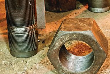
How to prevent bolt thread galling and seizing?
Galling is caused by a combination of friction and adhesion between metallic surfaces during sliding. When galling occurs, material is adhesively pulled from one surface, leaving it stuck on the other in the form of a lump. This process spreads rapidly as the built-up lumps induce more galling.
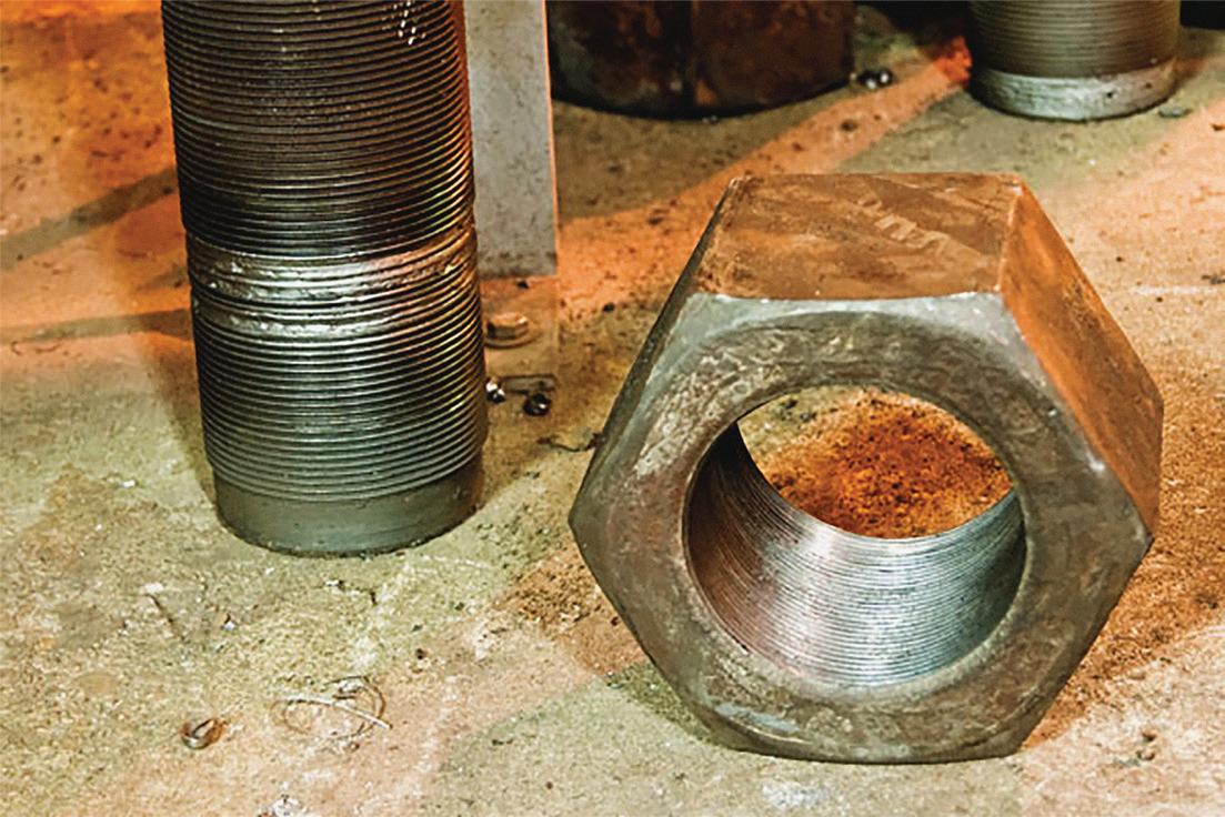
The tendency of a material to gall is affected by the material’s ductility. Typically, softer materials are more prone to galling and harder materials are more resistant.
In bolting, thread galling appears during fastener tightening as pressure builds up between the contacting and sliding thread surfaces. Thread galling commonly occurs with fasteners made of stainless steel, aluminum, titanium, and other alloys.
In extreme cases galling leads to seizing — the actual freezing together of the threads and bolt lock-up. Continued tightening may lead to the breakage of the fastener or result in torn-off threads.
The solution:
1. Lubricating the internal and/or external threads.
2. Reducing the installation RPM speed.
3. Selecting different stainless alloy grades for the bolt and the nut to reduce galling resulting from different degrees of hardness. Just remember, the strength of the nut always needs to be greater than the strength of the bolt.
DESIGN WORLD www.fastenerengineering.com December 2022 23
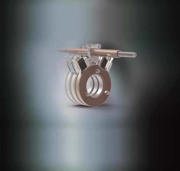
Load transfer factor or LFT calculations can showcase the need for changes in the loading conditions, joint design, or tensioner design solution.
Global Presence

ADVANCED TECHNOLOGIES
Since 1955 ND Industries has specialized in the development of innovative materials and processes which increase the safety and reliability of fastener assemblies.


ND serves a global market with divisions across the continental US, Taiwan, and licensees around the world. ND’s core business revolves around the application of a wide variety of materials onto fasteners and assemblies to aid in functions such as locking, sealing, masking, lubricating, and noise and vibration dampening. ND also manufactures a line of bottled products under the Vibra-Tite® brand name for MRO and retail use.
ELECTROLOC®

High strength encapsulated epoxy threadlocker for use in electrical systems where low halogen materials are necessary. Contains small micrometer microcaps which reduce material extrusion on installation.


THERMOSEAL™
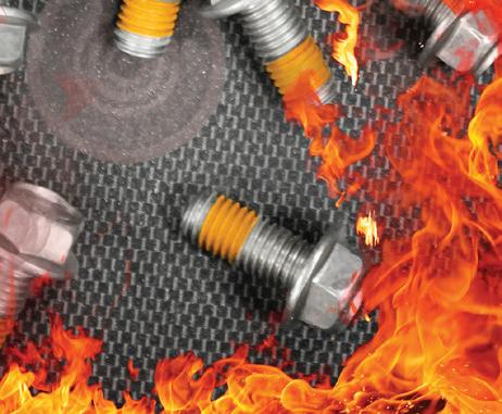
A high temperature, high pressure thread sealant which withstands up to 40MPa. Offering thread locking breakaway torques greater than 20Nm and a maximum temperature of 428°F (220°C). Thermoseal is an extremely versatile product for challenging sealing conditions.


THERMOLOC® 1500
ND’s highest temperature chemical threadlocker. Initially performs like a vibration dampening compound. Once temperatures reach 750°F (400°C), a secondary activation begins, causing the fastener to be permanently locked in place. Tested to over 1500°F (850°C).
•
•
•
•
Customer Service Driven
Vertically Integrated
Innovative Products


CONTACT US THREAD ARMOR® GP ND PATCH® HI-TEMP Prevents galvanic corrosion in assemblies with dissimilar metals, such as aluminum, and steel, by electrically isolating the fastener. Specially bonded to the fastener, ND Galvanic Patch is durable, chemical resistant, and non-conductive. Highest temperature pre-applied nylon threadlocker in the industry. Unlike the competition, ND’s application process requires only 120°C, preventing plating damage. However, once crosslinked, it can withstand temps up to 260°C. Meets MIL-DTL-18240F / QPL-18240. An advanced anti-galling and lubricating thread coating designed to extend the life of bolts up to 15 times while under intense torque and high friction loads. Helps to ensure consistent clamp load. Works well on stainless steel fasteners. This pre-applied threadlocker consists of separated epoxy hardener and expoxy resin. Upon fastener installation, the two materials mix and activate. When fully cured, EpoxyLock provides greater breakaway torque than conventional nylon fastener locking devices. A unique pre-applied microencapsulated expanding threadlocking & sealing compound. Increases in volume 20-50% on installation, penetrating the gaps in fastener threads typically unfilled by conventional threadlockers. www.ndindustries.com www.vibra-tite.com info@ndindustries.com Extruded ND Mastics are pre-applied to fasteners (threaded or non-threaded), bound for e-cote cycles. Heat from the process causes the material to expand, sealing large leak paths between fastener and assembly. An acrylic-based sealing material which is applied to the underhead of the fastener. SealTek’s robust seal replaces the need for O-rings, gaskets, or sealing washers. THREAD ARMOR® VC EPOXY-LOCK® NUTS EXPAND-A-LOCK® EXPAND-A-SLEEVE™ SEALTEK™
How advances in latches and hinges are enhancing user experiences
Recent changes in end-user application requirements have been driving new developments in latch and hinge technology — two common devices, often seamlessly integrated into applications. New features and capabilities are providing more options that optimize the end-user experience.
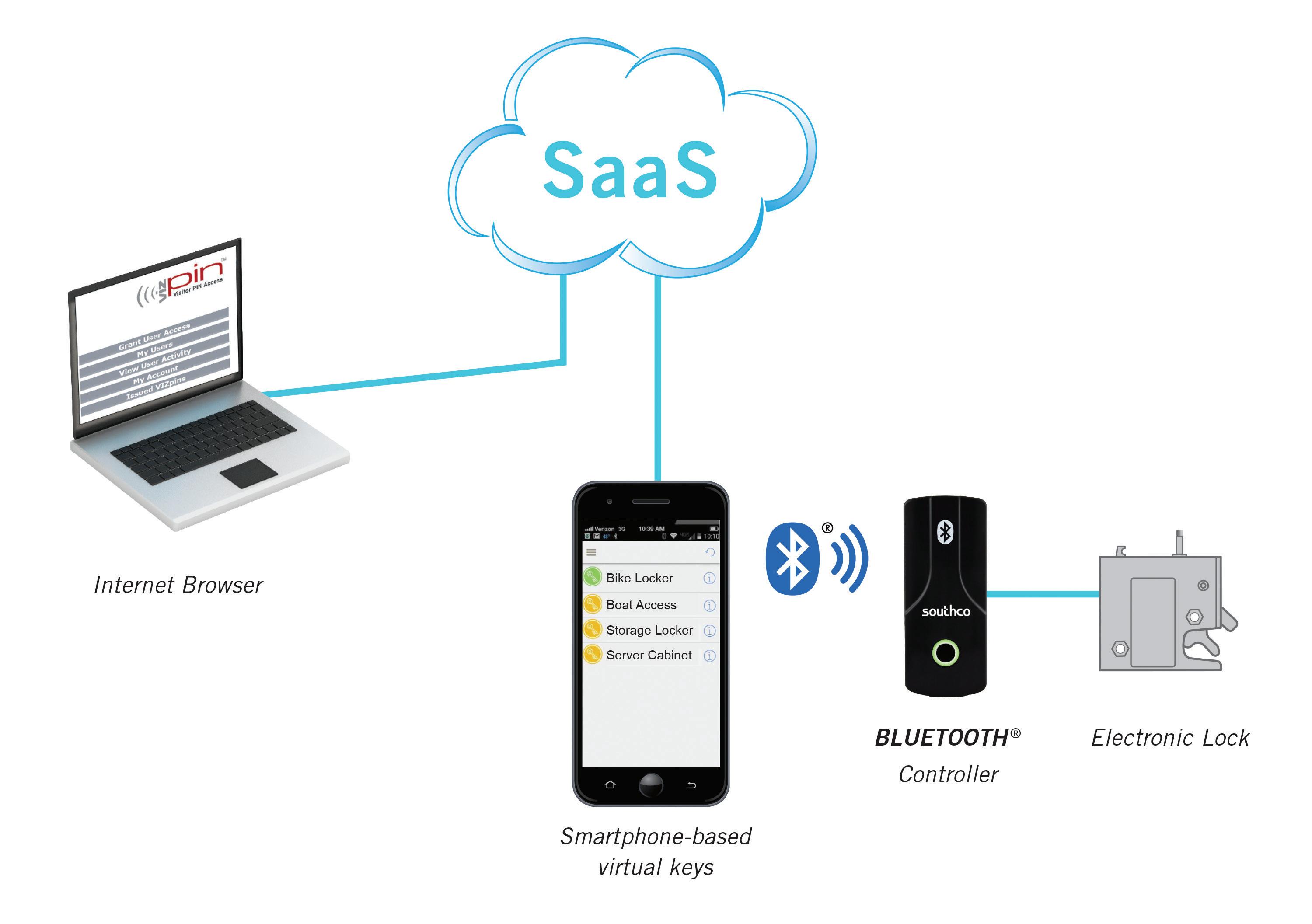
Latches range in complexity depending on the application zone, security requirement, ease of use, and other ergonomic factors. From simple cam locks securing an access panel to compression latches that create a clamping force between two surfaces, conventional latches fit several applications. Modern electronic access solutions (EAS) combine electronic locks with electronic credentials, such as RFID cards or smartphone-based access, ensuring more secure and convenient latching with remote-access control and monitoring.
Door hinges offer a similar range of function-based options. Fixed-position detent hinges hold open doors at pre-determined angles, eliminating the cost and labor of additional components. Counterbalanced positioning hinges provide lift and freedom of design for positioning panels or screens.
Regardless of choice, design engineers are focused on innovation and greater functionality for today’s latches and hinges.
The latest latching tech Demand is strong for all major categories of latching systems — cam or rotary, compression, push-to-close, draw, and sliding latches. One significant trend is the use of certain latches outside their typical applications.
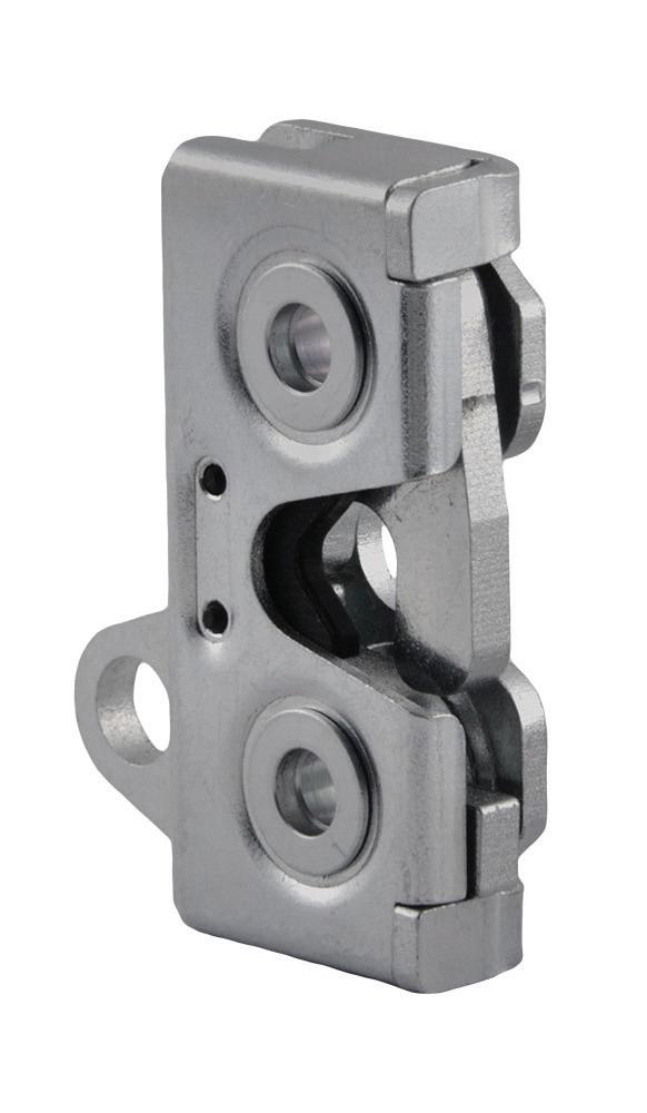
For example, the rotary latch is a simple yet durable device that’s the go-to mechanism for car and truck door handles. This
Hidden solutions feature sleek push-to-close operation with a space-saving design that facilitates interior door mounting. This is Southco’s R4 Rotary Latch solution.
use case has been extended to secure panels, such as doors on ATMs or self-service kiosks in restaurants and convenience stores. Access to these kiosks is restricted to technicians and personnel refilling cash and printout materials (in the case of ATMs).
Rotary latches provide a more secure solution than push-to-close latches and can be actuated with a physical key. They can incorporate electronic actuation and be controlled and monitored electronically in applications where a higher level of security or remote actuation is necessary.
26 December 2022 www.fastenerengineering.com DESIGN WORLD HARDWARE
Steve Spatig, General Manager, Electronic Access Solutions, Southco & James Stroud, Manager of Product Management, Southco
Electronic access solutions (EAS), such as electronic locking and access control devices, are increasingly used in commercial vehicles such as delivery vans and utility trucks, as well as offhighway construction, agricultural, and mining equipment. EAS can be connected to an existing network to track equipment access.
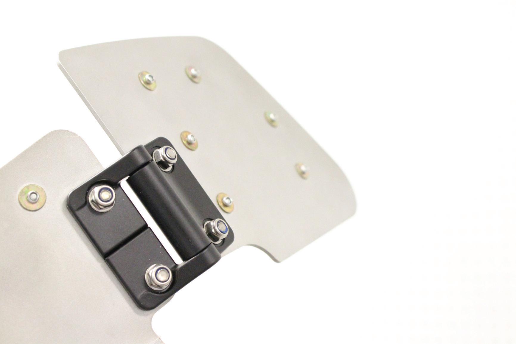
Constant torque positioning hinges, such as Southco’s E6 Series, provide reliable positioning with consistent operating efforts, eliminating secondary support components to hold doors or panels in position.
Additionally, rotary latches are now used in industrial applications, such as exterior panels on rail cars. In such high-vibration applications, some manufacturers are enhancing the latch with rubber bumpers to protect against vibration-generated wear and tear and deliver longer lifecycle performance.
Other more sophisticated latching systems are also in demand in atypical applications, such as on and offroad all-terrain vehicles (ATVs) and utility task vehicles (UTVs). These vehicles are designed for rugged environments, but users are requesting greater interior amenities and design features similar to those in high-end automobiles.
As a result, ATV and UTV manufacturers are upgrading door and storage compartment latches
to provide a higher-end touch-point experience. This includes push-to-close or “slam” latches that shut with a single push on the door. A physical and audible “click” when closed assures a user the panel is secure, so the vehicle is safe to operate off-road.
Another development is the growth of the electric vehicle (EV) market, which is leading to new challenges for electronic locks, which are standard devices in these cars.
A fundamental engineering task for EV manufacturers is power management and maximizing the efficient use of the vehicle’s battery. Electronic latching suppliers are developing extremely lowpower mechanisms to minimize the power requirement of these devices and offering self-powered battery-operated solutions.
New
hinge positioning control Hinge technology has become more sophisticated, with features incorporating
DESIGN WORLD www.fastenerengineering.com December 2022 27
hardware
higher-quality experiences for users. The fastest-growing types of hinges are those with constant torque technology. With this kind of positioning hinge technology, designers can define and adjust the operating effort required to move or position doors, display screens, safety shields, and lights — or virtually any mounted component that’s opened, closed, and moved.
Hinges with integrated constant torque enable single-handed adjustment of connected monitors. Constant torque hinges use engineered friction to provide a specific resistance against motion. For instance, they enable the positioning of a cab operator’s screen at any angle with a simple adjustment. The screen must maintain that angle until re-positioned, even when the vehicle is in motion.
These same hinges are also useful in a vehicle’s center console. So, instead of using one hand to hold the console door open (while searching for an item),
Hardware trends
it’s possible to unlatch and pull it open, where it remains until closed.
Manufacturers have also advanced the hidden hinge, particularly for use on the exterior of enclosures and vehicles. Hidden hinges, which can also incorporate constant torque technology, are easily installed on the back side of a door or panel and fit flush with the fixed portion of the vehicle or enclosure.
These hinges offer two advantages: security and design. Security is enhanced because thieves and vandals can less quickly identify potential pry points, given the hidden hinge points. Hidden hinges also let industrial designers create sleeker, more streamlined designs, elevating the appearance of public enclosures and enhancing a vehicle’s visual appeal.
Access hardware manufacturers are continuing to innovate their product portfolios, incorporating new technologies, functionality,
and materials to enhance the touch point experience of users. Through ongoing consultation, collaboration, and engineering, expect even more innovations in the future.
Market dynamics are continually impacting the development of latch and hinge technology and the delivery of products to multiple industries. One ongoing trend is the global supply-chain disruptions caused by the pandemic, which is still making it difficult for OEMs to obtain latches and hinges without high costs or delivery delays.
This includes automotive, aerospace, railway, RV, and construction manufacturers. Few markets, if any, have been spared.
Suppliers and customers can expect delays with latching systems that use electronics and require microprocessors. There are also material shortages, such as plastics and steel, because supply plants were mostly idle during Covid. Production restarts are still lagging.
The result is that suppliers are strengthening and diversifying their manufacturing footprints and material supply chains to meet demands more effectively. Many companies are collaborating more closely with customers and, for example, supplying alternatives when a specific model or type of latch or hinge is in short supply.
It’s ideal to work with an innovative manufacturer or supplier that can offer options and expertise.
28 December 2022 www.fastenerengineering.com DESIGN WORLD


Overcome Your Challenges with NBK Special Screws Modi cations Available
: Vacuum Application Screws Plastic Screws (PEEK) Captive Screws Vacuum Application Screws Special Surface Treatment Screws Low Pro le Screws Functional Clamping Screws Low Pro le Screws
:
Screws (PC)
Cap Screws
Screws (PPS)
Screws
Material Screws (Phosphor Bronze) Plastic Screws (PTFE)
Screws 307 East Church Road, Suite 7, King of Prussia, PA 19406 phone: 484-685-7500 fax: 484-685-7600 e-mail: info.us@nbk1560.com www.nbk1560.com
Left
Right
Plastic
Cover
Plastic
Captive
Special
Titanium
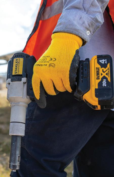
installation
What are the different tightening methods for a screw?
Hiroki Goto, Engineering Manager, NBK America LLC
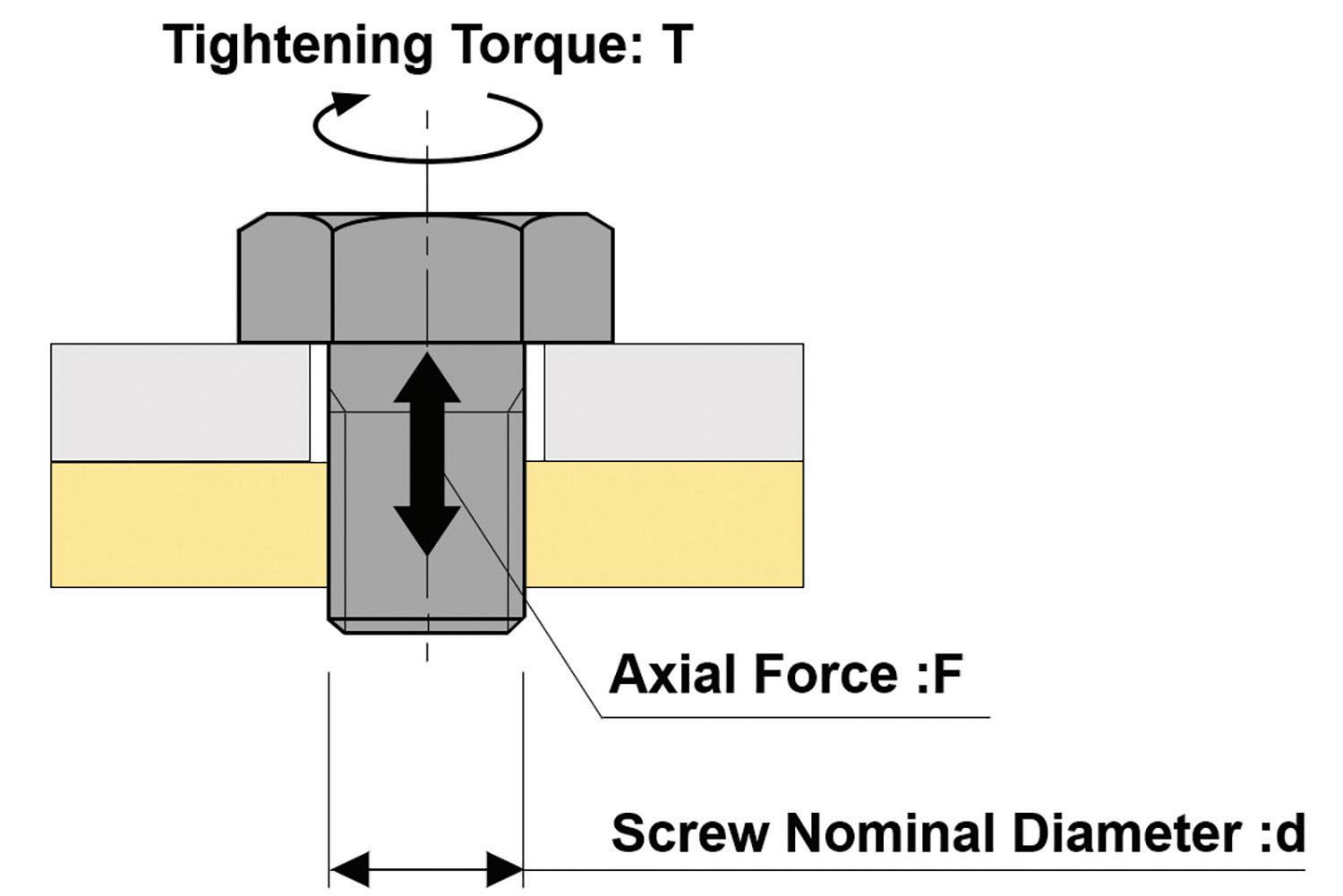
There are several ways of securing parts together, but the screw, a mechanical fastener with a threaded shaft, is still the most common. The primary role of screws (and bolts) is to fasten objects using axial force generated from tightening.
Typically, the torque method is used to install a screw, which refers to managing tightening torque with a torque wrench to control the axial force on the screw. A torque wrench is common because it’s relatively simple and easy to use.
However, there’s more than one control method for tightening screws and bolts.
The tightening regions
Before explaining the different tightening control methods, let’s first cover what it means to tighten in the “elastic region” and the “plastic region” of a screw.
The relation between tightening torque (the force required to rotate the screw) and axial force in the elastic region is expressed by this formula: T=kdF
T : Tightening torque (N·m) – the force required to rotate a screw
k : Torque coefficient – the amount of variation in the axial force when screws are tightened under the same conditions, so the larger the value, the greater the variation d : Screw nominal diameter (m) – the size of the screw threads
F : Axial force (N) – the applied stress or tension
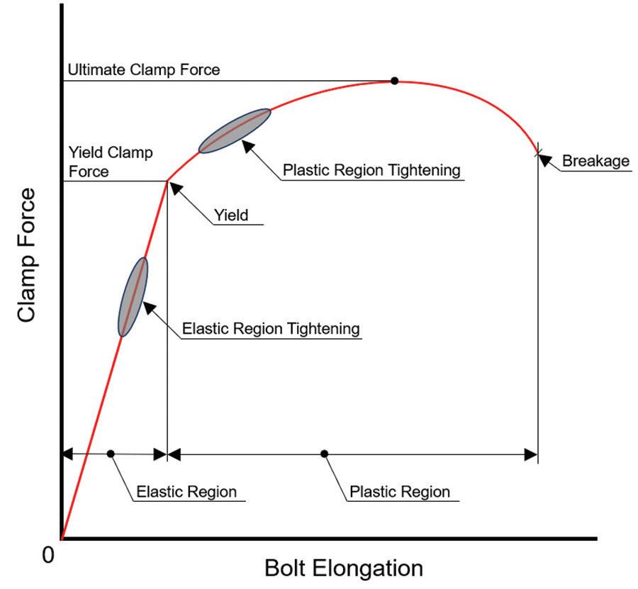
When you progressively apply an axial force by tightening a screw, the screw elongates in proportion to the force up until the yield point. Yield load is the load at which the material deforms beyond return to its original state. When the force is removed, the screw returns to its original elongation. This is referred to as the elastic region. Tightening within this range is called “elastic region tightening.”
If axial force is applied by tightening the screw beyond the yield point, the proportional relationship disappears, and the
elongation in relation to the force increases rapidly. In this state, permanent elongation of the screw occurs, and it does not return to its original length.
If the screw continues to be tightened past this point, it will eventually break. This is the plastic region, and tightening within this range is called “plastic region tightening.”
The variation in axial force on the screw in elastic region tightening is quite large, so the screw can be used repeatedly with the torque method (and a torque wrench).
In plastic region tightening, permanent elongation of the screw occurs, which has drawbacks and cannot be done repeatedly. This tightening method takes time to perform but offers more stable control of the axial force than elastic region tightening. Its often used in critical and industrial applications, such as automotive engine assembly.
The methods
There are three control methods of tightening a screw or bolt:
1. Torque method 2. Torque gradient method 3. Angle of rotation method
The torque method is a tightening control method that uses a linear relationship in the elastic region between the tightening torque (T) and the clamp force (F). Since this method is only for controlling the tightening torque during tightening work, it’s a relatively simple and popular method (typically, with a torque wrench).
However, the entire tightening torque does not act as an axial force; some of it is expended through friction with the screw’s thread face and the seating surface. As a result, the axial force will vary significantly according to certain conditions, such as the surface roughness and lubrication condition. Care is needed in controlling the friction characteristics, even when tightening with the same torque.
30 December 2022 www.fastenerengineering.com DESIGN WORLD
Tightening torque is the force required to rotate a screw. The torque method refers to managing tightening torque with a torque wrench to control the axial force on the screw.
Therefore, it’s generally recommended that screw tightening using the torque method is done with generated axial force around 60%~70% of the yield point within the elastic region.
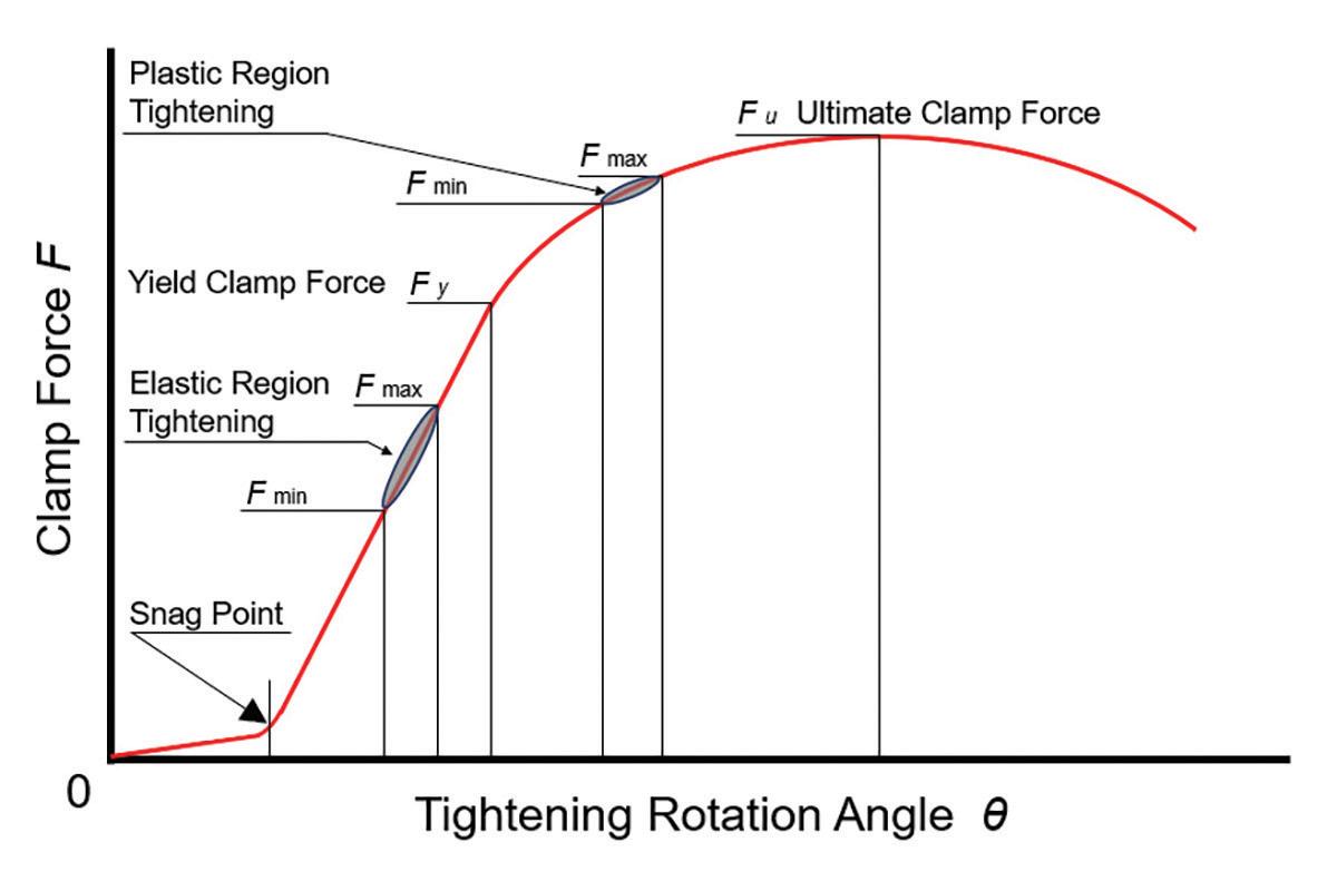
The angle of rotation method regulates the clamp force by controlling the tightening rotation angle from the snag point of the screw head or nut. The snag point is the point at which the required tightening torque forces the screw and seating surface tightly together.
This method calculates the angle on a pointer scale (a protractor) or with an electrical detector and is used for elastic and plastic region tightening.
Typically, the torque method is preferred for elastic region tightening because of its simplicity — and because the axial force varies when applying the rotation angle. But with the plastic region tightening, the change in the axial force due to tolerance in the rotation angle is smaller. For this reason, it’s sometimes possible to control the angle by sight, watching the hexagonal form of the bolt or nut.
The torque gradient method uses clamp force on the screw, exceeding the yield point. So, the elongation of the screw increases rapidly relative to this force. An electrical sensor detects the tightening torque and rotation angle. The change point between the elastic and plastic regions is calculated by a computer and tightening is performed at the limit of the elastic region.
Large-scale equipment is required for this method, but variation appears only in response to the material yield point. And the variation is much smaller than with the torque or angle of rotation methods. The torque gradient method is only used when high tightening reliability is required, such as with the bolts in automotive engines and cylinder heads.
There are also other methods to tighten a screw. One includes the measured elongation method, in which the elongation of the screw is assumed directly and controlled in that way. Another involves heat, in which a screw is heated at high temperatures to elongate it. Then, the temperature is controlled during mounting.
Each method is application-dependent, so it’s important to have a good understanding of the parts to be fastened and the conditions affecting them.
The effects of force: the elastic region is when a screw will still return to its original, undeformed state after stress. The plastic region is when this is no longer the case, and the screw deforms permanently.
The relationship between the tightening rotation angle and the clamp force. The snag point is the point of the nut tightening method at which the required torque acts to create close contact with the seating surface.
DESIGN WORLD www.fastenerengineering.com December 2022 31
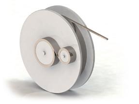
cold forming
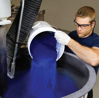
What is cold-form manufacturing?
courtesy of RISCO, Inc.
Cold heading or cold forming is a method that has been used for well over 100 years. The technology has come a long way since its origin but, essentially, still involves taking a piece of metal and forging it into a specific shape — without adding heat.
Cold forming has become a high-speed process that lets manufacturers produce large amounts of metal-based components in a fast, consistent manner.
For fastener manufacturing, cold forming is a quick and efficient method for producing standard and customized parts, including those with complex shapes. Compared to machining methods, cold-formed components are structurally stronger and more durable, offering products without compromising the natural grain flow of the material by forming as opposed to cutting. This also provides a smoother surface finish.
The material is never cut (it’s formed), so speed in manufacturing and material strength are two major coldforming advantages. This type of fastener manufacturing
is ideal for high-volume requirements, providing costeffective results for larger orders.
Forming, as opposed to cutting, greatly reduces the amount of scrap metal, which saves costs. In fact, cold forming is capable of producing up to 70,000 pieces within an eight-hour shift.
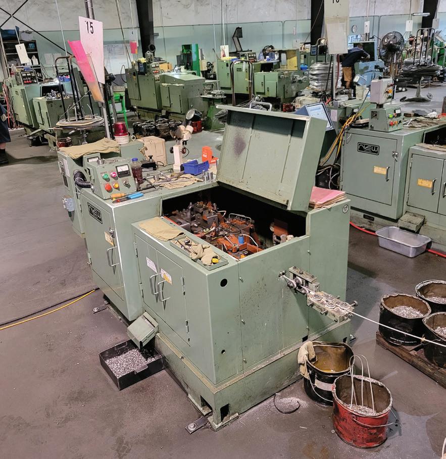
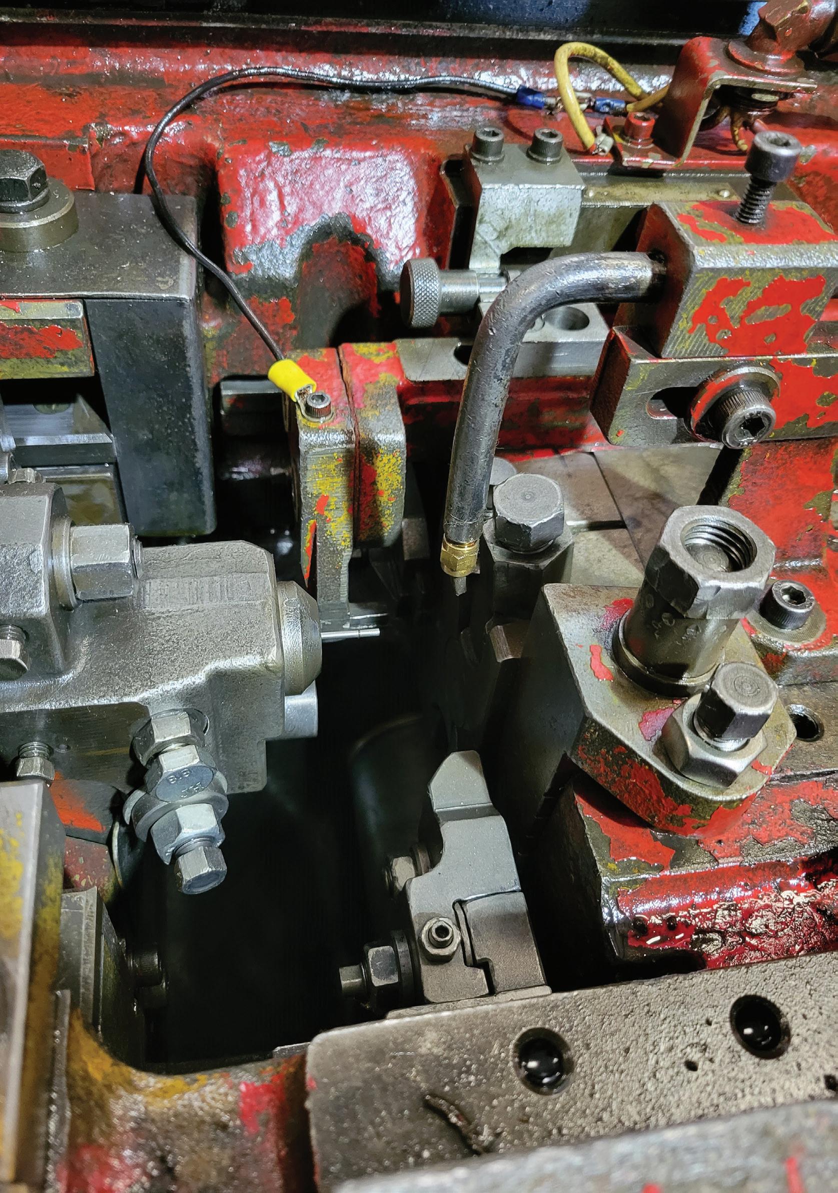
The machine
The most common type of cold header is a one-die, twoblow style. As the name suggests, these machines use one die to form the body of the fastener and two blows to forge the head of the fastener.
The first blow, or upset/cone blow, is the initial progression used to create the proper geometry of the part. It loads the blank into the die while starting the head forming. This process also forms the body of the part.
The second blow is known as the finishing one, which puts the drive (such as a Hex, 6-lobe, Philips, etc.) in the fastener and completes the initial process of cold forming a fastener. For more complex parts, some coldforming machines have several dies and blows, such as 2-die/3blow, 2-die/4-blow, or 3-die/3-blow — all the way up to six or more dies.
After the fastener is cold-headed, secondary operations are often used to complete the part, depending on the requirements. These operations include trimming, thread rolling, slotting, grinding, heat treating, plating, and others.
One thing to consider is that because parts are produced in such a high volume, there can sometimes be fluctuations for certain dimensions. It’s worth asking your manufacturer what tolerances they can hold. The tolerance is the acceptable amount of dimensional variation that will still allow the part to function properly.
Cold-form manufacturing is typically not recommended for low-volume, high-tolerance requirements.
A cold-header machine, which is used to form metal parts and fasteners.
32 December 2022 www.fastenerengineering.com DESIGN WORLD
Article
The
Manufacturer capabilities
Choosing a manufacturer that meets your requirements is essential to ensuring production to spec, product reliability, and on-time delivery. When it comes to cold-formed fasteners, here are a few considerations to discuss before placing an order.
• Manufacturer’s experience and certifications
• Quality-assurance processes
• Material availability
• Typical lead times
• Machine capabilities and tolerances
• Samples (ask if there’s a first article or part sample available before production)
This is one of the most common types of cold-header machines — the one-die, twoblow style.
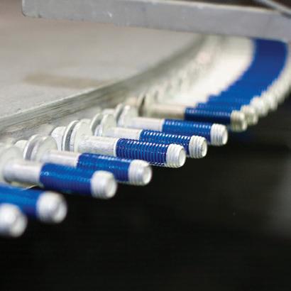
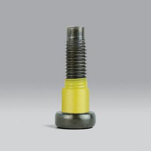
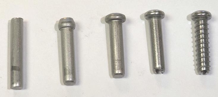
From start to finish: The manufacturing of a Phillips pan-head screw.
DESIGN WORLD www.fastenerengineering.com December 2022 33
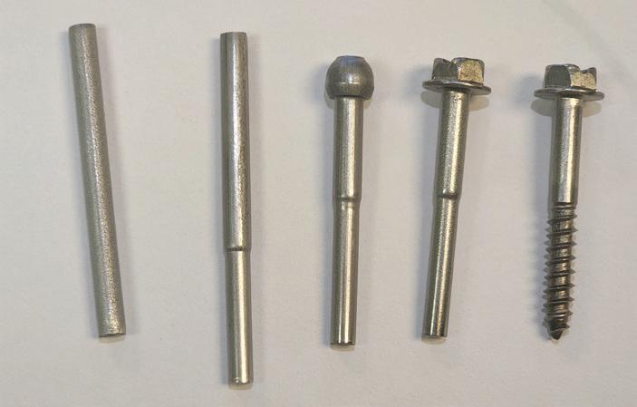
making of fasteners: Progression of a hex head with a washer.
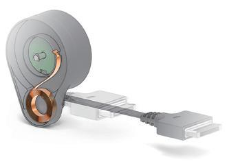
smart manufacturing
What is “smart mechatronics” and how can it support fastener manufacturing?
 Brad Klippstein, Product Management – Mechatronics Bosch Rexroth
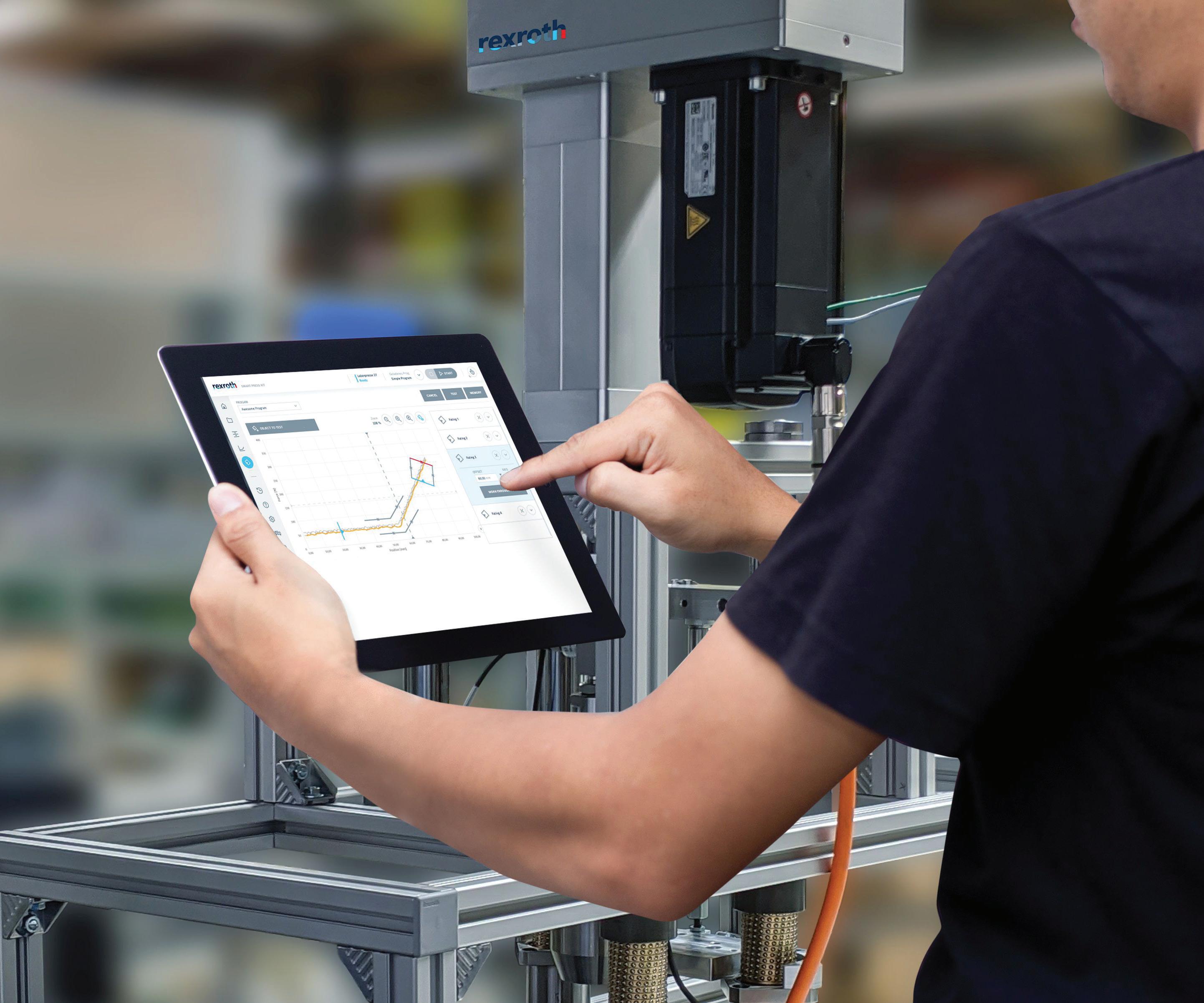
Assembly operations that use handling, joining, and pressing tools for a range of production applications — including fastener manufacturing — continually seek to improve the versatility, ease of use, production time, and quality of such operations.
In today’s digital world, this means adding smarter, Industry 4.0 capabilities to production platforms. For efficiency, this must entail data tracking of a machine’s production and performance with real-time sharing capabilities.
As manufacturers begin to incorporate the benefits of Industry 4.0 technology, a new concept called “smart
mechatronics” has evolved, offering more intelligence and functionality in handling and joining. Mechatronic systems are devices that have fully integrated mechanical and electrical components, thanks to the combination of sensors, circuits, and motion-control applications.
In some ways, mechatronic systems could be considered a forerunner of Industry 4.0 technology. They combine disparate mechanical and electronic components into solutions for specific product assembly and transport tasks, such as Cartesian robots (capable of moving in multiple linear directions) and forming and crimping tools.
Meeting industry needs
At one time, mechatronic solutions were integrated with components from multiple suppliers. That’s no longer the case. Mechatronics suppliers are replacing that time-consuming acquisition and integration step with complete solutions that are “plug and produce.”
This includes the software necessary, which is preprogrammed and delivered as a single production tool. Manufacturers should know that all of the components for a complete mechatronic solution — a Cartesian robot or a pressing or joining tool — can now be specified
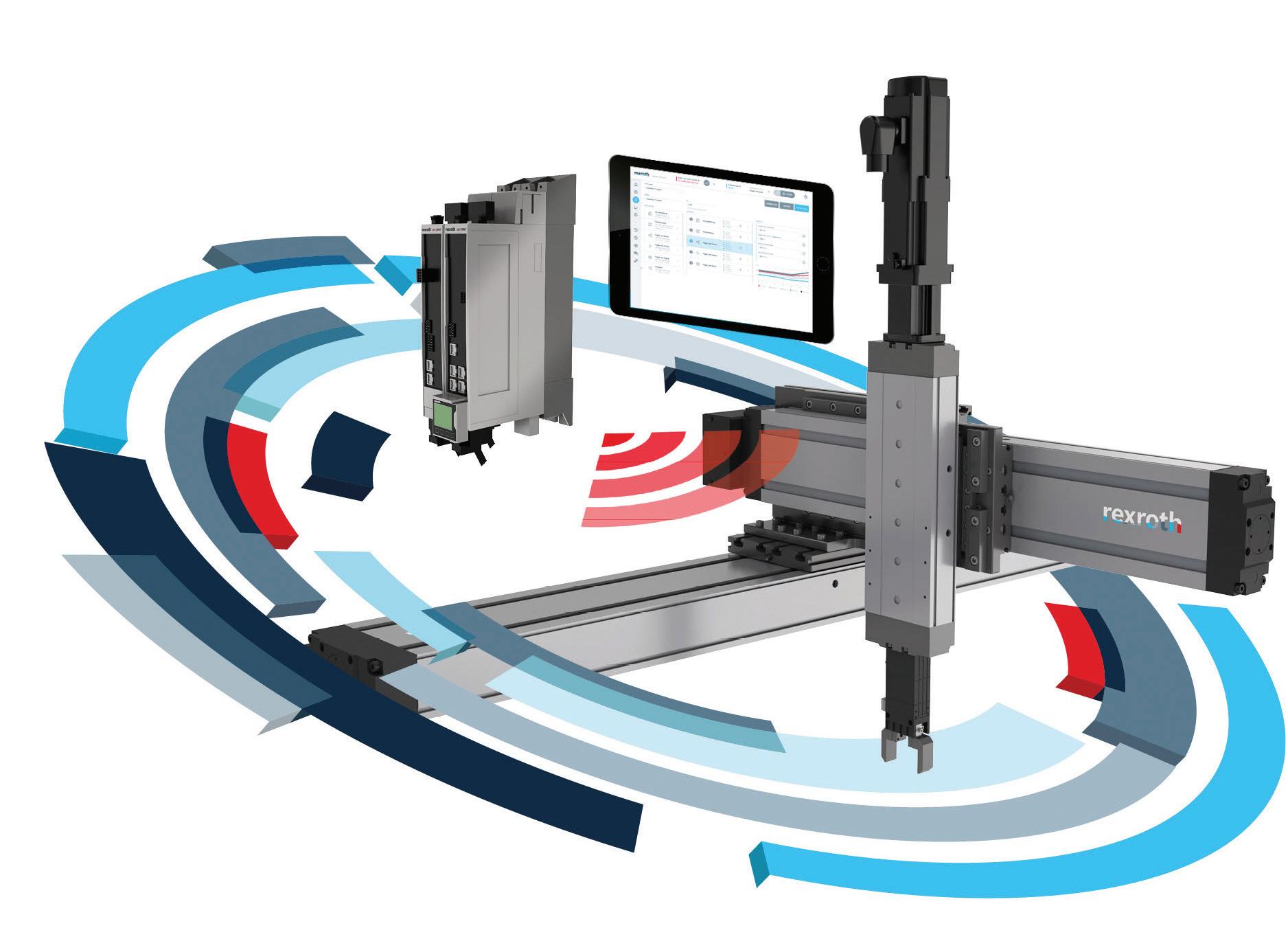
Assembly operations are shifting away from individual products toward complete system kits for manufacturing equipment that produces fast solutions for handling, joining, and pressing tools — along with real-time data.
34 December 2022 www.fastenerengineering.com DESIGN WORLD
in a single process. Users can enter parameters such as stroke, workpiece weight, and cycle time, which generates an output that can be verified in the CAD environment.
It’s clear end users require precise control and execution of motion sequences, but also automated tracking of production data and easy connectivity with machine-level and plantwide production management systems.
Additionally, there’s a demand for easier and faster changeovers. Many production lines or mid-sized shops seek tools that make it easier to produce a range of batch sizes — from the low end of only a few thousand parts up to hundreds of thousands — without extensive effort to reprogram tools for a new part.
The price point also matters. End users require cost-effective measures
that meet budgets and readily support manufacturing orders. Kitted solutions that provide flexibility in a space-saving envelope with minimal integration time are highly desired.
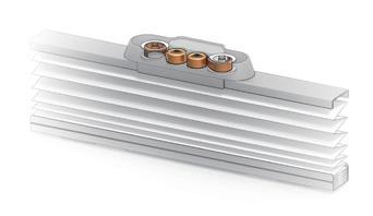
Easier, faster commissioning is one significant advance provided by newer, smarter mechatronic systems and the technology that supports them. Equally valuable are the improved efficiency, flexibility, and productivity it provides end users looking for easy-to-automate solutions.
For those wanting to integrate mechatronics and update production lines, consider systems that:
• Combine all the hardware and software into a single solution to support a broader range of applications, including pressing and joining, logistics, packaging, pick-and-place, palletizing, assembly operations, and more
Smart mechatronics solutions leverage easyto-use tools, such as dragand-drop functionality and simple programming. Bosch Rexroth’s Smart MechatroniX system for pressing and joining applications is one example that demonstrates this intuitive model.
• Feature an easy-to-use graphical user interface that lets operators build production sequences simply and intuitively
• Require no special motion-control or programming skills
• Monitor systematic data such as position, velocity, and acceleration
• Include kitted solutions that offer simple integration, flexibility, and tracking options, providing users with the ability to set conditions for automated quality control
• Provide real-time updates and recordings as requested
• Offer a multi-axis system that can interface with individual peripheral tools such as gripping devices, nozzles, and actuators
Times are changing, and so are industry requirements and processes. To keep up, fastener manufacturers are wise to digitalize their operations with Industry 4.0 technology.
DESIGN WORLD www.fastenerengineering.com December 2022 35
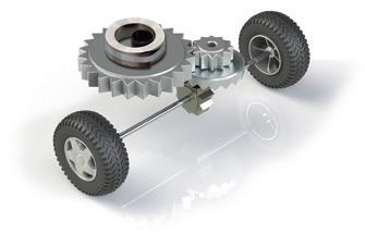
How is lightweighting affecting fastener materials and designs?
Chris Kanaan, Sales Manager, ARaymond
As fastener manufacturing advances, the lightweighting of fastener designs is also evolving. This is when a fastener is made lighter than typical, usually by replacing steel with other materials, such as aluminum.
However, joining lightweight materials can present challenges like different panel thicknesses, tolerances, retention requirements, corrosion — and the need to reduce the complexity of fastening interfaces. New fastener designs must meet performance and reliability standards, so developing mechanically and chemically compatible solutions are essential.
This trend in lightweighting is primarily driven by market demands. This is especially true in the automotive sector, given the growth of electric vehicles (EVs). The efficiency of EVs relies heavily on lighter-weight parts. This is also a requirement of the aerospace sector and several electronics manufacturers.
Material matters
Structural integrity and durability are critical when developing lightweight fasteners for any industry. Any new component design must include design and validation processes to ensure it performs as intended in any given application. This can be easier said than done.
Materials performance can vary depending on an application and the environmental conditions, so choosing wisely is a must. Material costs are also a consideration with lightweight compounds.
Currently, several manufacturers are moving away from heavier steel as a material for fasteners and toward other materials, including: • Aluminum • Carbon fiber • Multi-material assemblies • Nylon • Plastic • Titanium
These options typically let engineers shed weight from a manufactured fastener without shedding strength or reliability. In fact, many of these materials offer the same strength as a fastener made with heavier metals. Multi-material assemblies can also lower production costs. This is primarily thanks to new technologies and manufacturing processes.
Assembly advances
So, how can manufacturers lower the assembly costs of lightweight fasteners? One way is through the advancements in 3D printing. Another way is through the recent advances in plastics and multi-material assemblies.
3D printing – Also known as additive manufacturing, 3D printing builds a three-dimensional object from a CAD or a digital 3D model. One benefit is that it’s possible to print almost any design since there are no limitations on bends
36 December 2022 www.fastenerengineering.com DESIGN WORLD
materials
and cuts. This makes this technology a worthy consideration for fastener designs compared to injection molding.
It’s particularly ideal for prototyping ideas and for fasteners with unique shapes and materials. However, given today’s advances in 3D printing, if you can think it, you can print it.
Plastics and material assemblies –
Multi-material assemblies typically combine mild steels and rubbers/plastics, with the same functional properties as high-strength steels, but at a lower total cost of ownership. They also offer an overall reduction in mass, which is key for lightweight fasteners.
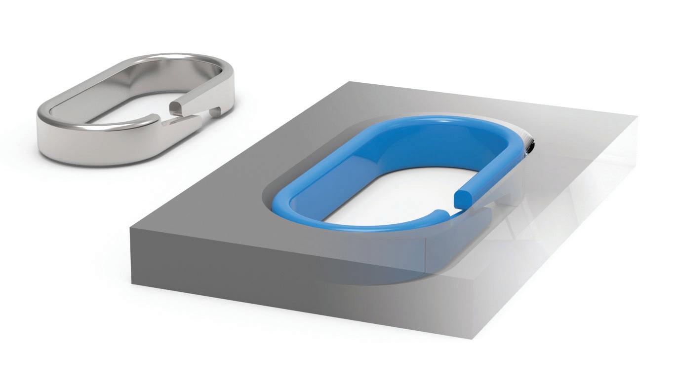
While it’s best to avoid bolting or screwing directly into nylons or plastics, overmolding provides greater design possibilities. Overmolding is an injection-
molding process where one material is molded onto a second one. It lets engineers use nylon material with an overmolded compression limiter, installed directly into the customer’s end item.
In this case, end users retain the high functional product requirements but gain critical cost and weight savings from their overall assembly.
Automotive implications
The fast-growing electric-vehicle market is providing an opportunity to upscale current production capabilities to support lightweighting in several EV applications, including structural connections, power connections, and thermal and moisture
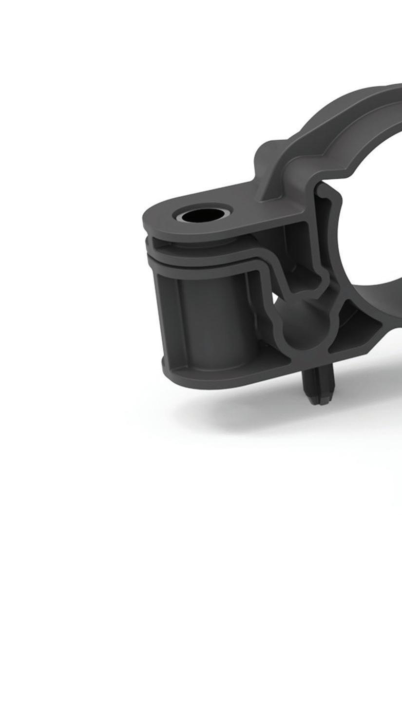
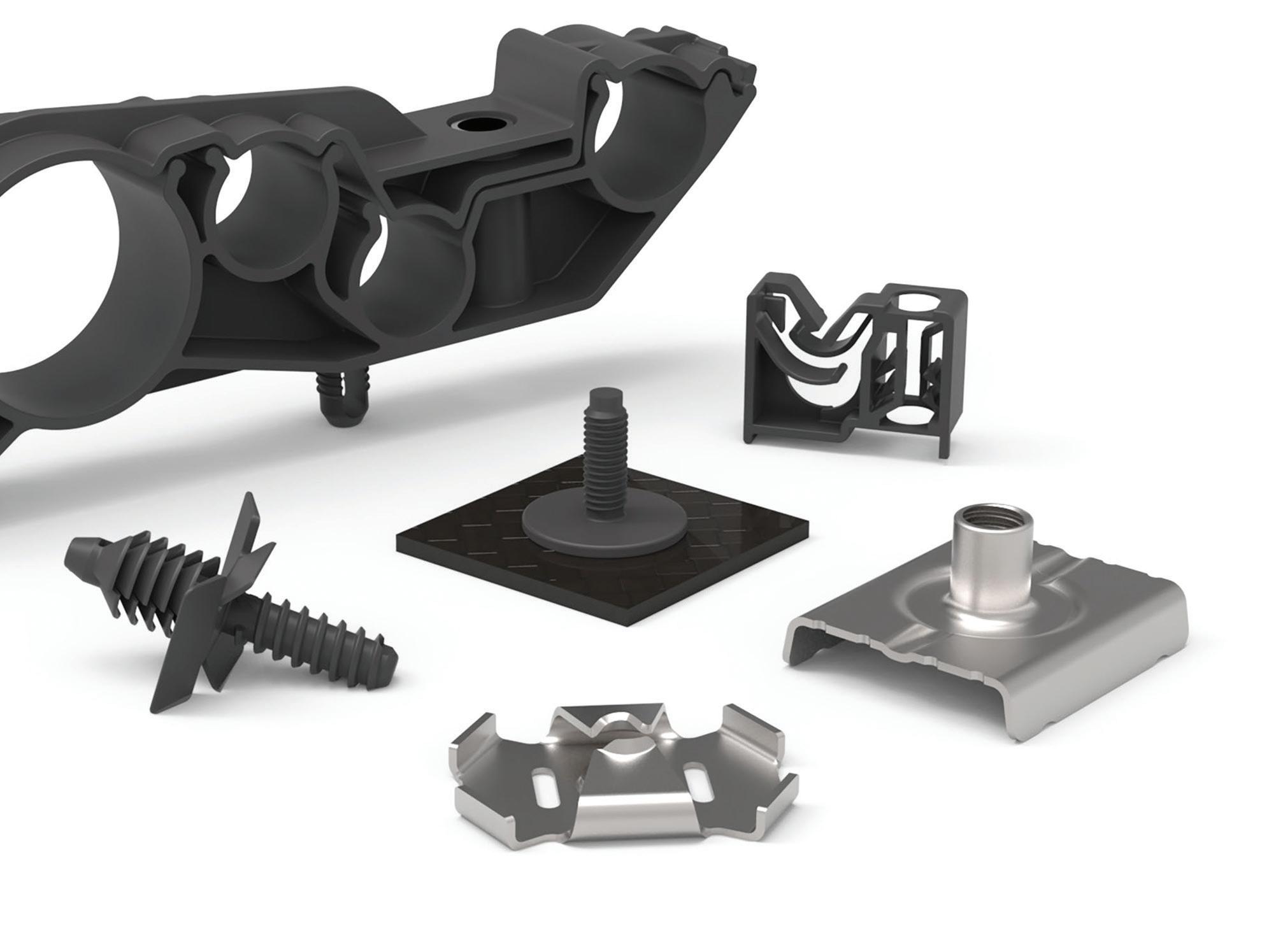
A few examples of lightweight automotive parts. They’re made with alternative materials to reduce weight by up to 50%. These fasteners from ARaymond can adapt to a range of panel thicknesses, enabling a load distribution that prevents damage to the parts.
DESIGN WORLD www.fastenerengineering.com December 2022 37
materials
Go design.
Learn more at Emerson.com/Medical
An overmolded compression limiter, which prevents creeping, for plastics and composite materials.
sealing.
Lightweight fasteners are rapidly replacing heavy metal joints and aiding in key EV areas of concern, such as water sealing and battery-pack optimization. There’s a safety aspect to these lightweight fasteners, too, such as the importance of securing the battery-pack lids.
Additionally, materials in EVs must have significantly higher heat capacities for potential thermal issues. For example, higher safety requirements for durability and flammability must be met, particularly for plastic or other resin-based materials.
Lightweight fasteners might come with a higher price tag than conventional, off-the-shelf parts, but for a good reason. And when the total cost of ownership is considered, the lightweight choice typically provides a greater long-term value.
New fastener designs also require communication and collaboration between OEMs and their supply base to best develop new standards and product lines for future success.
No matter the industry, the trend is clear: Lightweighting is a must-have tool for engineers as they develop fasteners that meet industry and assembly demands. Lightweighting is providing a key feature as manufacturers reinvent fasteners for changing market conditions.

38 December 2022 DESIGN WORLD
Emerson’s expertise in plastic joining and fluid control make complex medical devices more compact and easier to manufacture.


Sponsorship opportunities are available for future DeviceTalks and Robotics programs. For more information, contact Courtney Nagle. 440.523.1685 | cnagle@wtwhmedia.com SUMMIT & EXPO BOSTON, MA MAY 10-11, 2023 B O S T O N C O N V E N T I O N A N D E X H I B I T I O N C E N T E R boston.devicetalks.com | healtchareroboticsforum.com | roboticssummit.com
What are nut retainers?
Nut retainers are self-retaining spring steel fasteners that have a bolt-receiving nut floating inside a cage, which offsets typical hole misalignment. It does not turn when the bolt is tightened. Essentially, nut retainers combine the advantages of spring steel fasteners with the strength of a multi-threaded nut.
These components slide or snap into position (by hand) at panel edges or center-panel locations, making them ideal for blind assembly locations. They’re also a good choice for applications requiring extra-high torque and holding power.
No welding, clinching, staking, special skills, or equipment is required for installation. Another benefit: Nut retainers are rust-proof and can be applied after painting, eliminating costly masking or retaping of paint-clogged threads.
There are three main types of nut-retaining fasteners:
• Cage nuts
• J-nuts
• U-nuts
Cage nuts — also known as rack or captive nuts — combine a strong spring steel cage and a multi-threaded nut. They’re ideal for rack and equipment-mounting applications.
Cage nuts have spring-steel “mechanical hands” or wings that keep the nut stationary in a square hole, which helps with bolt insertion. As the nut is pressed to the locked position, the mounting legs expand around the panel and force past the retainer spring tabs, snapping back to lock the fastener firmly in place.
They can be applied at any convenient spot along the assembly line and are ideal for blind-assembly attachments. Applications include automotive, electrical, HVAC, cabinet construction, server racks, and others.
How to apply cage nuts:
1. Insert one of the cage nut’s retaining legs into the panel hole
2. Snap the other leg into the hole by hand or with a simple tool
3. Align the second panel, and then thread the bolt onto the captive nut.
4. Tighten the bolt into the self-retaining nut
5. A positive, high-torque, flush attachment is achieved
J-nut or J-type retainers combine the strength of a nut with the flexibility of a spring steel cage. They easily snap over panel edges or can be inserted into rectangular holes in central panel locations. Floating alignment and retention are attained with extrusions in the retaining legs, which snap into panel mounting holes — allowing the fastener to shift or align but not disengage.
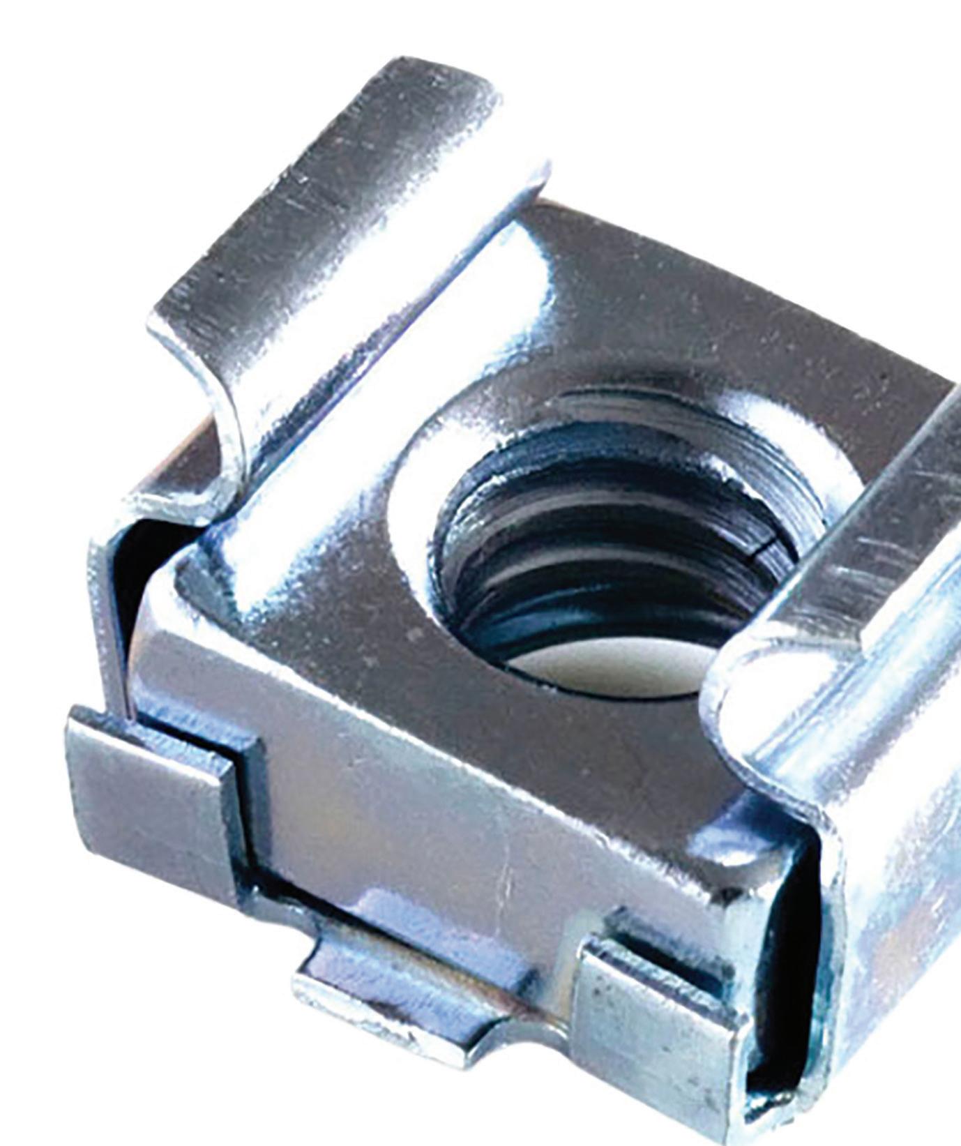
Installing J-nut retainers does not require special tools or skills because they simply snap into place anywhere on the assembly line. They serve as a heavyduty fasteners for blind location assemblies, including for use in the automotive, appliance, HVAC, and other industries.
How to apply J-nuts:
1. Push the J-nut into place on the panel or a rectangular hole that’s in the panel’s center
2. Snap the extrusion into the hole
3. Position the second panel and the drive screw
4. Align the panels
5. Flush-mounting is obtained by embossing either panel
40 December 2022 www.fastenerengineering.com DESIGN WORLD NUTS
Article courtesy of Advance Components
U-nut or U-type retainers provide the same advantages as J-nuts. They o er a low profile and heavy-duty fastening when combined with a machine screw that’s ideal for blind location assembly. They’re self-retaining and will not turn when the screw is driven.
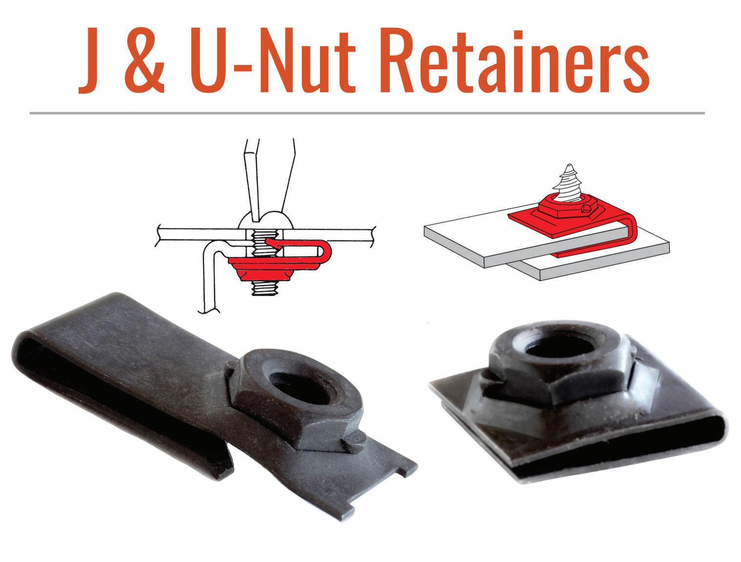
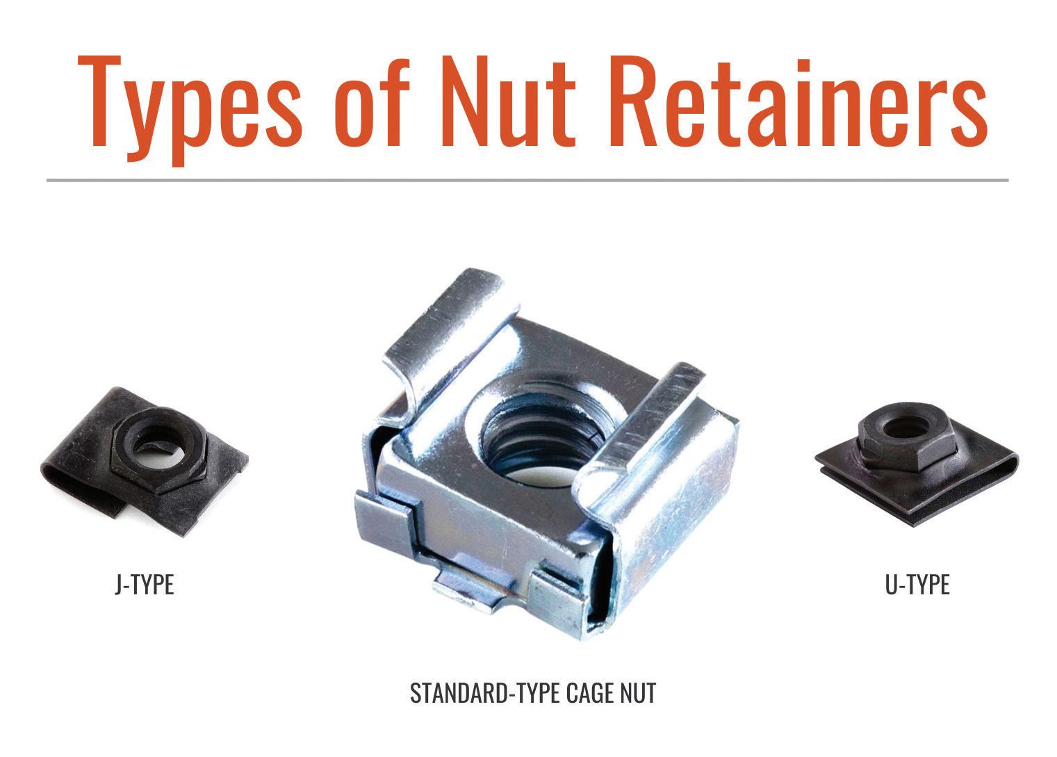
U-nuts maintain constant alignment with an extrusion on the lower leg. Button-hooked into center panels or pressed over flanges, they retain themselves with “mechanical hands” formed from the spring steel retainer and are held securely under live spring tension. They’re easily applied by hand or with simple tools and are used in several applications, including electronics, vending, appliances, automotive, marine, and others.
How to apply U-nuts:
1. Push the U-nut into a bolt-receiving position on the panel or in the rectangular hole in the center of the panel
2. Snap the extrusion into the mounting hole
3. Position the second panel and drive in the screw
4. Ensure flush mounting is obtained
5. Access to the back of the panel is unnecessary to complete the assembly
J- and U-nuts provide simple, rapid, and self-retaining attachment of mating panels. They’re often a preferred alternative for larger screw sizes.

Cage nuts are used to attach components to panels with square holes. The nut floats within the cage to account for normal build variation.
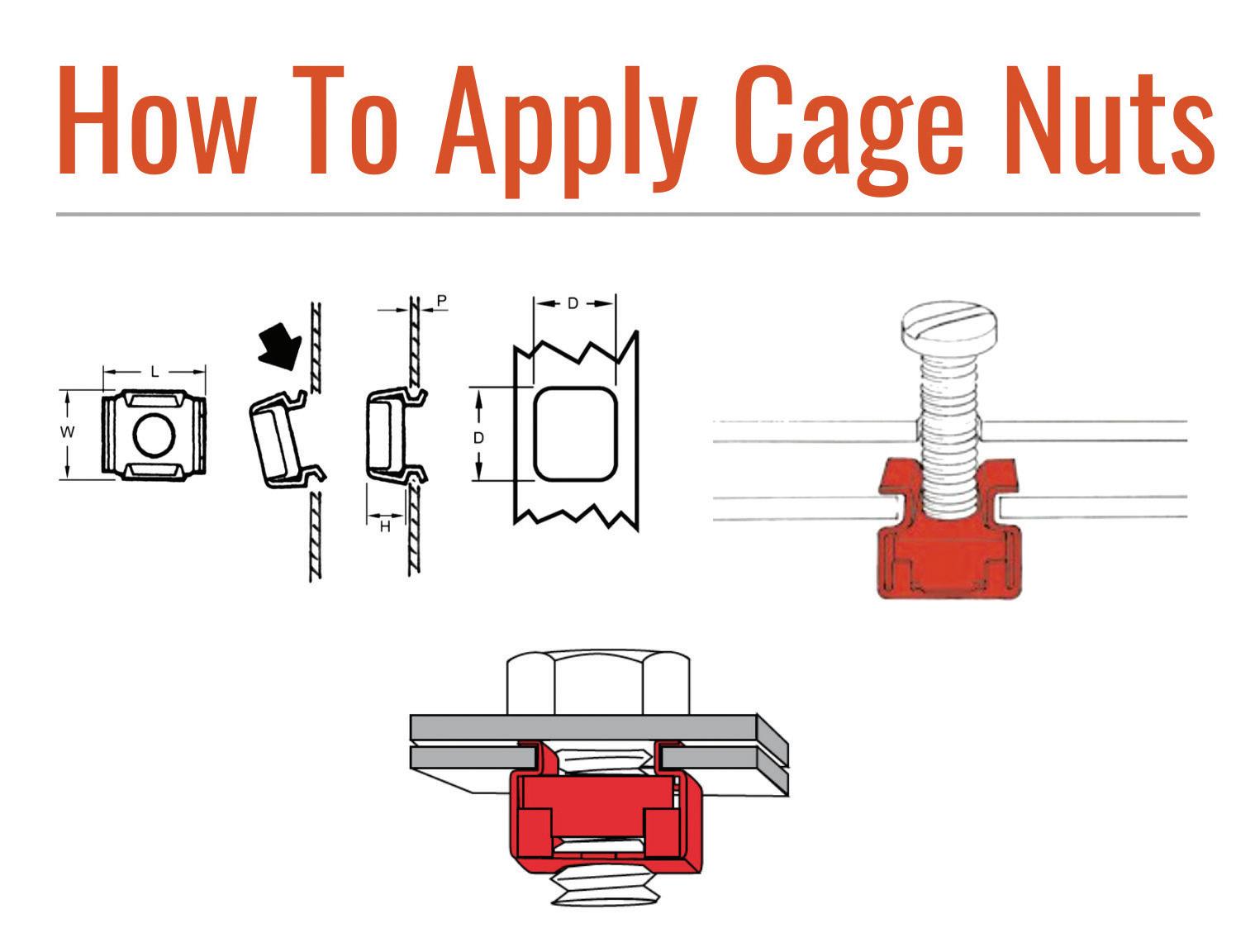
DESIGN WORLD www.fastenerengineering.com December 2022 41
The self-retention feature of nut retainers improves assembly time and eliminates costly welding and clinching costs.
pins
What’s the difference between cold-headed and machined solid pins?
Jones, Vice President, Director of Marketing SPIROL International Corporation, U.S.A.
Solid pins are fasteners used for aligning, joining, and assembling multiple components. Ideally, these pins are selected when the clamp load of a bolt is unnecessary. They’re typically used for specific functions such as locating components, hinges, tamper-resistant designs, etc.
Cold heading and machining are two of the most common manufacturing methods used to produce solid pins, and both result in high-quality, consistent parts. It’s important to understand the differences between cold heading and machining when designing solid pins for an assembly, as the manufacturing method directly impacts the design specifications (including the tolerances, geometry, and material).
The objective is to design a solid pin that optimizes performance and reduces the total manufactured costs of the assembly.
Manufacturing methods
Machining is the process of cutting raw material (rod) into the desired geometry using cutting tools. This operation is typically performed on a lathe. Machining produces scrap in the form of chips.
Cold heading is the process of forming raw material into the desired geometry by upsetting the material (wire) in one or more dies. The most common method of cold-heading fasteners uses one die and two blows, which is sufficient for forming chamfers and heads. The dies provide the cavities used to form the preferred geometry and the blow describes the physical process of upsetting material with a machine stroke.
There are limitations to the amount of material that can be displaced per blow. And as the geometry becomes more complex, additional dies and blows are required.
Cold heading sometimes includes a wire-drawing process that work hardens the material, increasing the yield and tensile strength. Machined pins produced with the same base material will have a lower yield and tensile values because the material grain structure has been interrupted.
Design specifications
The first step in designing a joint is to establish the functional requirements of the host components and fasteners. Performance requirements should be achieved without over-specifying the design. An ideal joint satisfies performance and quality requirements at the lowest possible cost.
Tolerance
Typically, the outside diameter (OD) is the most critical solid pin dimension.
Cold heading and machining can achieve the tolerance specifications needed for most of these applications.
In fact, cold heading produces solid pins
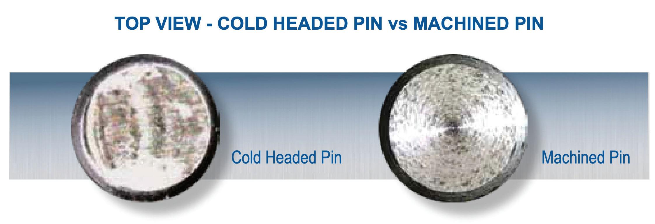
42 December 2022 www.fastenerengineering.com DESIGN WORLD
Christie
with OD total tolerances of 0.05mm (.002”), which is less than the thickness of human hair. Machining can achieve tighter OD tolerances, but this usually requires a special ground OD rod, which should be avoided if possible (the ground OD rod can be more than three times the cost of a standard rod).
For the length tolerances, machining and cold heading can achieve the same tolerance levels of approximately ± 0.25mm (± .010”), which varies by pin length.
The chamfer is used for ease of assembly. A chamfer angle between 25° to 40° is suitable for most applications, allowing for maximum pin engagement. From a manufacturing standpoint, the optimal cutting angle (machining) is 45°, and the optimal forming angle (cold heading) is 30° or less.
It’s worth noting that press-fit dowels and straight pins are typically retained in the assembly by being pressed into holes smaller than the pin diameter. The interference, therefore, must be limited in most applications to keep insertion forces within practical limits.
The acceptable press fit for most metals (steel, brass, and aluminum) is 0.0125 to 0.025mm (.0005 – .001”) of material displacement. Since this tolerance threshold includes the sum of the pin and hole diameter tolerances, pins must be precision machined
Know when to use…
A machined solid pin:
• Low-volume custom parts
• Highly critical alignment applications
and holes must be reamed and/or honed. This increases cycle time and manufacturing costs associated with the hole preparation.
Also, note that free-fit hinges do not require press-fit holes and or pin diameter tolerances tighter than ± 0.025mm (± .001”).
Material
The most common materials for solid pins are carbon and stainless steel. The raw materials are available in different forms depending on whether pins will be machined (rod) or cold-headed (wire).
Commercially available material grades for rod and wire can differ. Rod is available in material grades best suited for machining, and wire is available in material grades suited for cold heading. Best engineering practices dictate that material specifications on drawings remain general (i.e., carbon steel with hardness rating RC 27-33).
Costs
Machined solid pins are typically 10 times the cost of cold-headed pins.
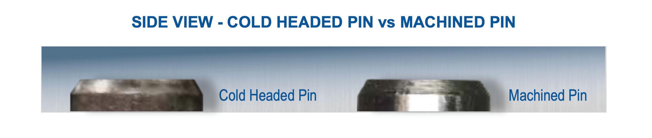
Here are a few reasons why:
• Speed. Cold heading produces solid pins at a rate of about 300 parts per minute (ppm), while machining yields about 4 ppm.
• Scraps. Machining generates leftover material, so more is needed for the same part. The only scrap generated during cold heading is that produced during set up.
• Expense. Ground OD rods can cost more than three times as much as a standard rod used for machining.
However, setup costs are significantly lower for machining. Companies that standardize on solid pin sizes can mitigate setup costs, so there’s only a negligible cost impact for customers. Custom designs are a different story, especially at low volumes.
It’s recommended that manufacturers partner with industry experts in joining and assembling to identify the lowest cost solution for their assembly.
• When functional requirements dictate complex pin geometry
A cold-headed solid pin:
• Majority of applications (as most do not require machined tolerances)
• Free-fit axles/hinge pins where the pins are slip fit into place
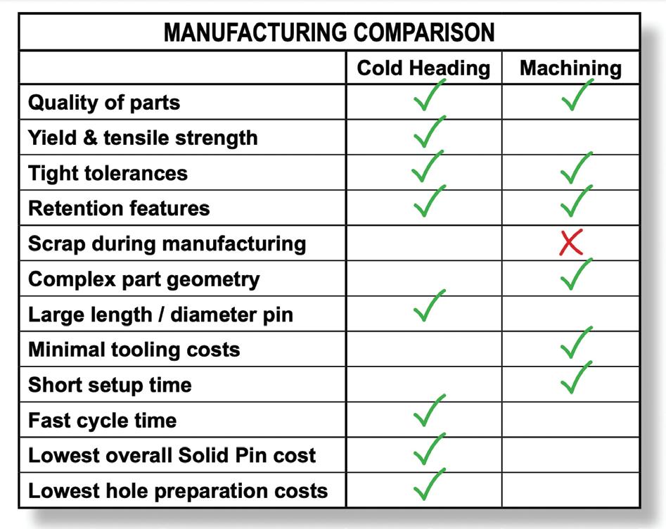
DESIGN WORLD www.fastenerengineering.com December 2022 43
PLATING
What is plating and what causes electroplated coatings to fail?
Successfully working in the fastener industry entails ongoing learning, even for experts in the field. Case in point: a recent learning experience was on plating adhesion.
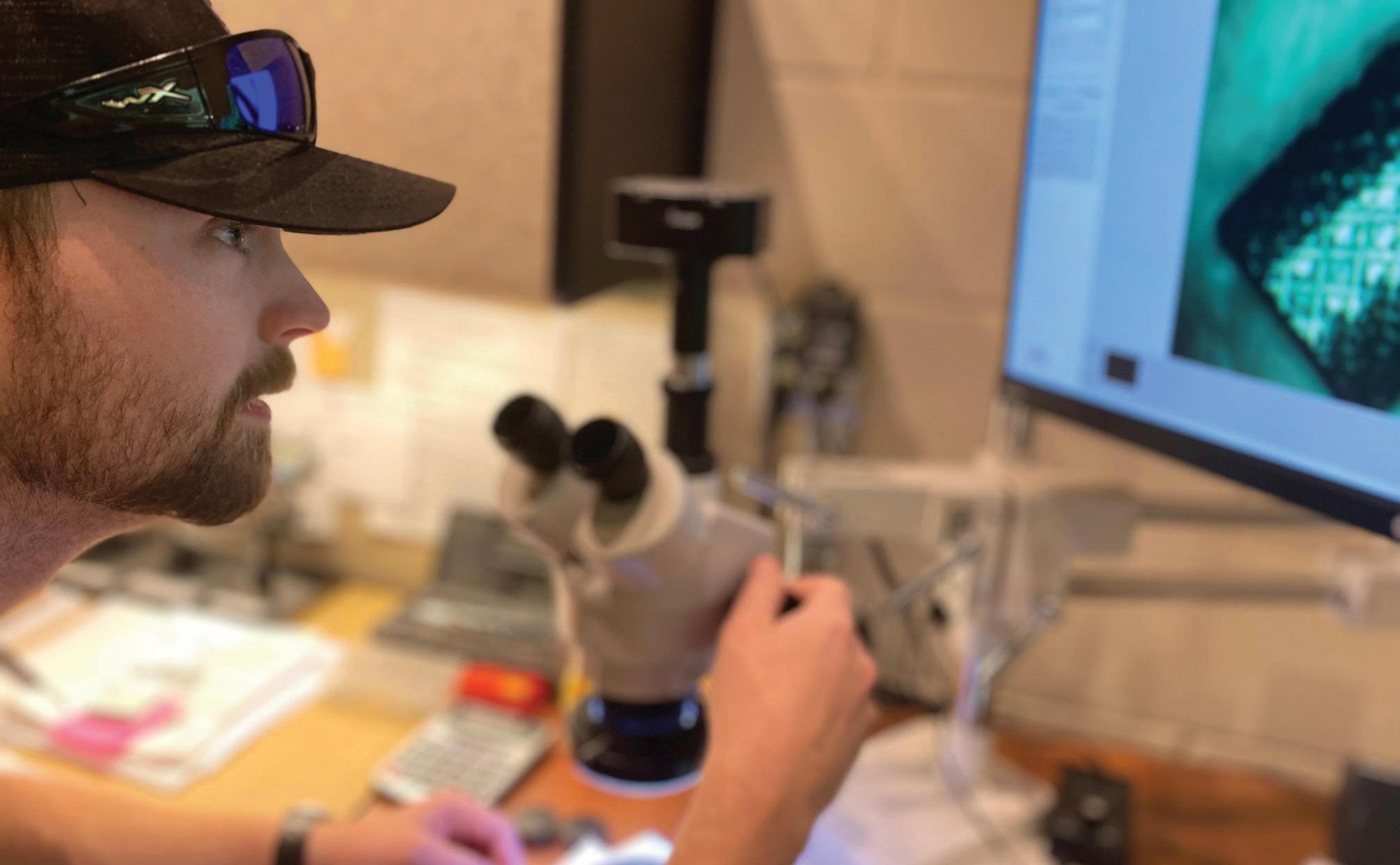
Plating is a thin layer of metal bonded or fused at the molecular level to the fastener. Depending on its purpose, plating can alter a fastener’s appearance, hardness, electrical conductivity, or ability to withstand corrosion or wear.
There are several types of plated coatings available, including zinc, phosphate, chromium, nickel, bronze, brass, and many others. In this case, type 260 brass fasteners with nickel plating per ASTM B733 SC1, Type III were in production. Nickel plating provides a unique combination of wear and corrosion resistance, including visual appeal.
The problem was that a plating process change occurred without verification. The reason: the screw manufacturer moved plating facilities to meet the customer’s production deadline. Although this plating facility indicated it could properly plate the screws to specification, no testing was performed to confirm the plating or qualify the new plater.
Manufacturers rely on different tests to ensure the reliability of their fasteners. For example, salt-spray testing is common. The coating will typically indicate the minimum hours to rust when tested in a salt-spray test. There are also plating adhesion tests to ensure the coating does not peel or flake. Additionally, it’s important to ensure the plating provider’s equipment and process standards also meet quality requirements.
For this project, everything seemed fine at first. Dimensionally, the plated parts conformed to print, and their appearance was nearly identical
44 December 2022 www.fastenerengineering.com DESIGN WORLD
Jennifer L. Sturm, Chief Operations Officer, Empire Bolt & Screw Inc.
Mason Smith, examining the plating surface under 100x magnification at Empire Bolt & Screw’s Quality Control Lab. Smith is the company’s account manager and a QC technician.
to previous lots. However, during installation, these parts proved faulty due to plating adhesion failure. The nickel flaked off when installed in the application.
Flaking can occur for a few reasons, including inadequate surface treatment, incorrect coating thickness, or interruptions or errors during the plating process.
This customer’s print called for a nickel-plated brass fastener that would be inserted into a mating threaded terminal and then installed into a terminal block. The process also employed automation, so there were a lot of considerations to examine to find the root cause of the failure.
Through a process of elimination, the terminal, block, and automated processes were eliminated as the cause. Following the results from the XRF scan, there were two contributing factors that led to the plating failure.
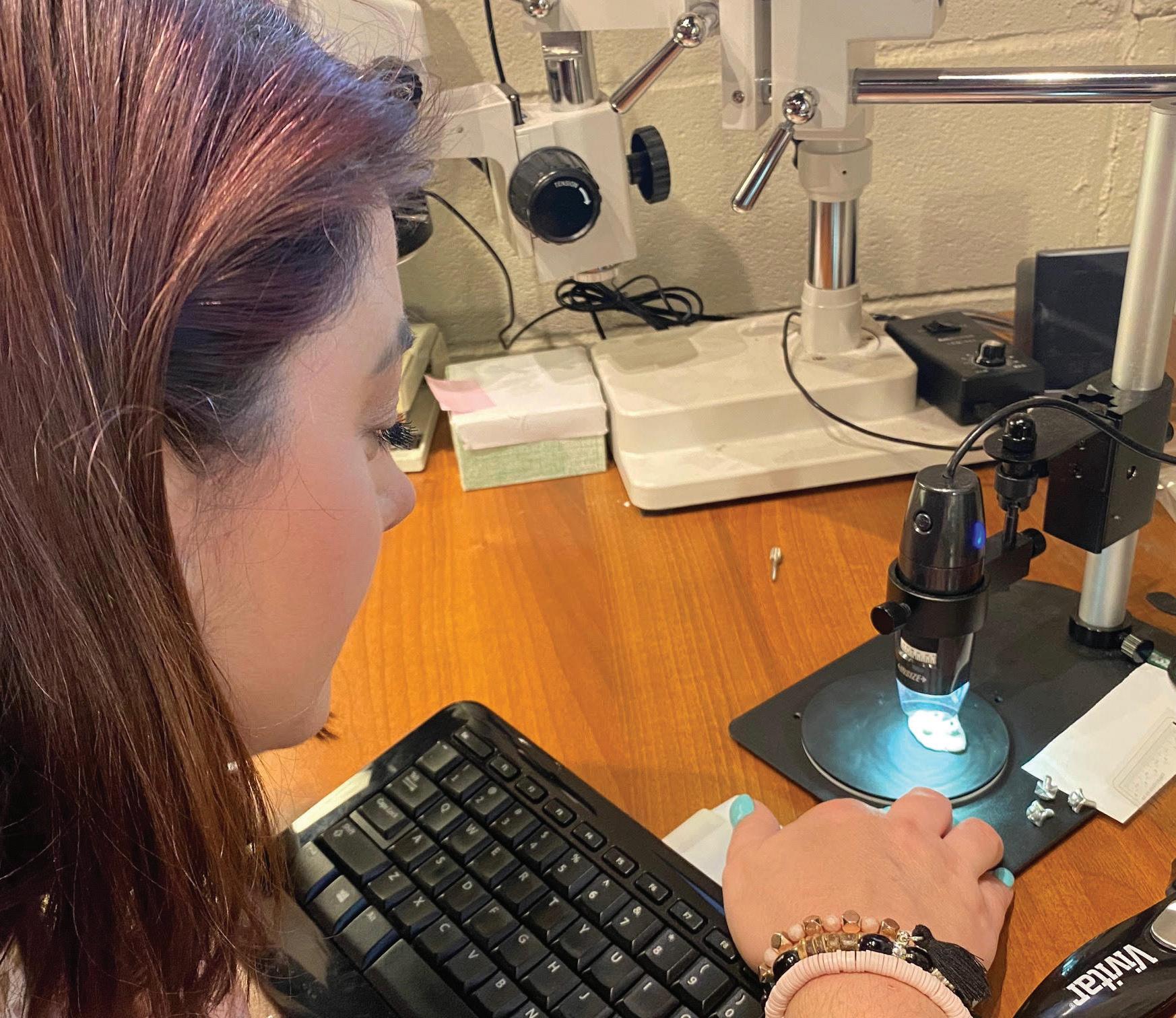
1. The electroless nickel plating was not to spec. It was less than half of the required thickness. All documentation indicated that the plating process was followed according to the standard, but under XRF, it was clear that the plating was insufficient. (XRF is an X-ray fluorescence spectroscopy that determines the elemental composition of materials.)
2. A copper flash was used to help the electroless nickel adhere to the part. However, on all lots that pre-dated the rejected lot, a nickel flash was used instead of copper.
Finding the right test
The next challenge was finding a method to ensure the adhesion of the plating on subsequent manufactured lots would be described on the print. Within ASTM B571, appropriate adhesion test methods are indicated for a variety of coatings. ASTM International, formerly known as American Society for Testing and Materials, is an international standards organization. For nickel plating, there are 11 test methods.
The bend test was considered at first, but there was no way to adequately bend these parts around a mandrel to achieve accurate testing results. Next, the Heat-Quench test method was used as it’s non-destructive. The test subjects electroplated parts to elevated temperatures, determining the sufficiency of coating adhesiveness.
At first, the plating passed with no visible blistering to indicate inferior
adhesion. Unfortunately, the parts failed in the application and plating flakes were found after removing the fasteners from the terminal.
A more reliable method was necessary, ensuring the parts functioned properly in the application. Even ASTM places a disclaimer on the “precision and bias of these tests, because of their qualitative nature” (ASTM, 2013, 15.1). In other words, the results of the tests can be open to interpretation.
Ultimately, this customer specified the plating process must contain a nickel flash, and the parts must be plated with the full thickness of .0002 nickel (per ASTM B733 SC1, Type III or Type IV). The testing methods accepted must also meet Class 1 for adhesion (ASTM B571 verified) or Class 5 (heat treating) per ASTM B571.
To ensure conformance, additional testing with an XRF device will be employed to ensure an adequate deposit of nickel. Documentation will be provided with each plating batch within each manufactured lot.
So, what was learned overall? Although conformance is critical, it’s also wise to build strong, supportive relationships in the industry with those who are available for consultation. Even with the best of intentions, errors and unexpected events occur. It’s also essential to keep learning.
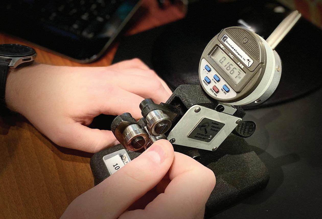
DESIGN WORLD www.fastenerengineering.com December 2022 45
Amanda Lundberg, a QA trainee, is setting up the comparator for fastener thread inspection.
Gaging threads with a tri-roll gage — specifically, the functional diameter.
rivets
How to best choose and install rivet nuts?
Rosa E Hearn, CFS, Product Manager Proferred Rivets Brighton-Best International
Since the original rivet nut was invented in 1936 to attach de-icers to aircraft wings, this versatile fastener has found new uses in several industries. Developed by BF Goodrich, these components were initially sold under the trademark name RIVNUT, but today you’ll find several brands in various shapes and sizes as a type of blind fastener.
Rivet nuts are unique, internally threaded fasteners anchored from only one side of a workpiece or application. Like a blind rivet, they’re installed from the front of a workpiece and are ideal for use when there’s limited or no access to the backside.
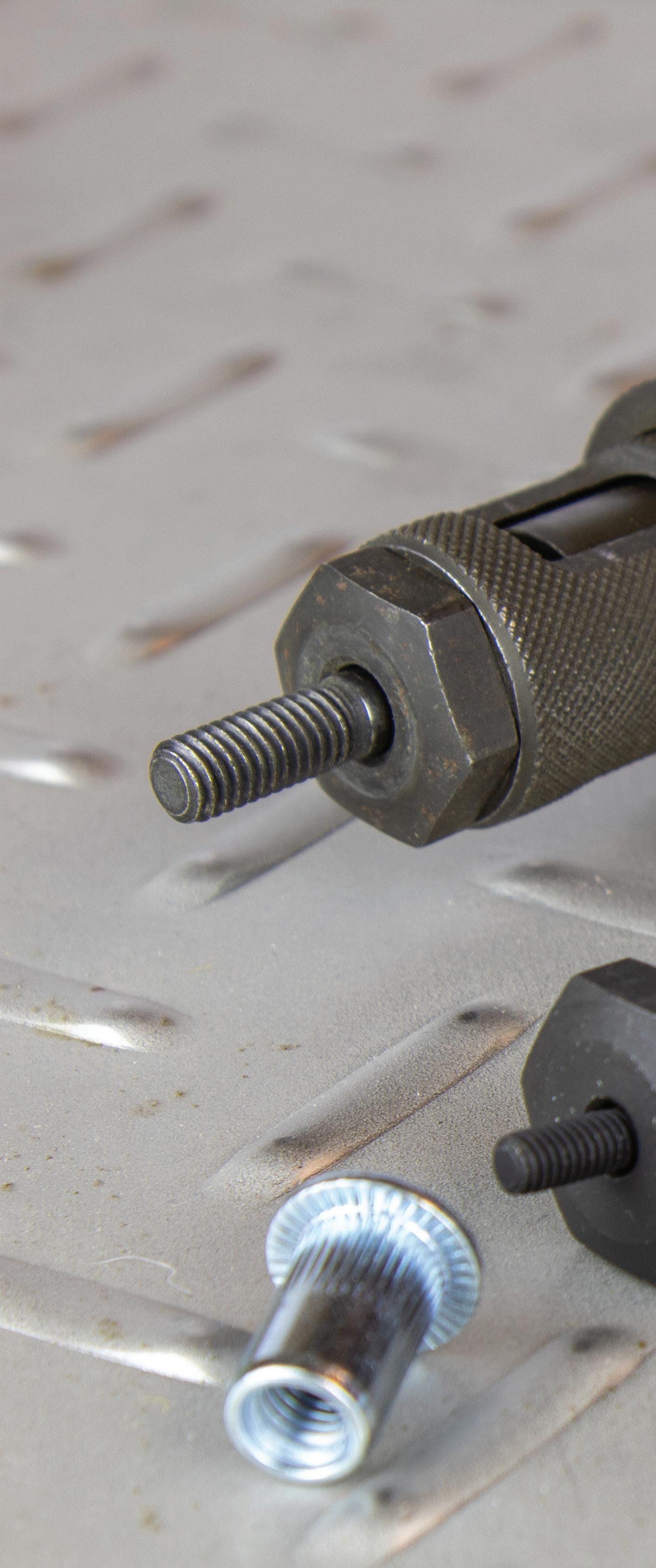
Rivet nuts are tough, versatile, and dependable. They reduce or eliminate the use of loose hardware, typically reducing assembly costs. They’re commonly used in aerospace, automotive, electronic, HVAC, appliance manufacturing, and any other industry using thin materials.
Proper installation
Did you know that a socket-head cap screw is required to install a rivet nut? This is called the mandrel. It was created to provide loadbearing threads in thin sheet materials that are too thin for a tapped thread. Rivet nuts add strength to thinner materials, making them an excellent choice for manufacturers focused on lighter-weight applications.
Most rivet-nut tools come standard with two or three socket screws. The standard sizes are 3/8, 5/16, and M8. For non-standard sizes (1/4-20, 1/4-28, M6, M10, etc.), the purchase of a separate mandrel is necessary.
Too often, the socket-head cap screw (mandrel) is not given the attention it deserves to ensure proper rivet-nut installation. A correctly sized mandrel must extend beyond the face of the anvil — far enough to allow at least one thread of the mandrel to protrude past the end of the insert.
If the cap screw has damaged threads, installation problems can and will occur. Damaged threads prevent the mating part from fastening correctly, leading to costly rework or scrapped parts. To prevent this from occurring, ensure the cap screw occupies all the rivet nut’s threads. This will help ensure the internal threads avoid distortion or uneven compression when the rivet nut is cinched to a workpiece.
Rivet-nut setting tools use an alloy socket-head cap screw. This prevents wear on the threads of the tool since they’re stressed repeatedly during the pulling of the part. Typically, the longer the screw (within reason), the better the performance because the forces are spread across more threads.
If the threads are repeatedly damaged, it’s possible that a worn (softer) bolt is the problem. A well-worn bolt typically leads to the first few threads getting marred, which ruins the nut — and, therefore, the screw.
46 December 2022 www.fastenerengineering.com DESIGN WORLD
Condition of the mandrel
For most tools, the mandrel is a standard ASTM A574 socket-head cap screw. The threads should be clean and lightly lubricated to ensure a proper and smooth installation. It also extends the life of the mandrel. If unwaxed, the installers should apply oil to the cap screw end before use.
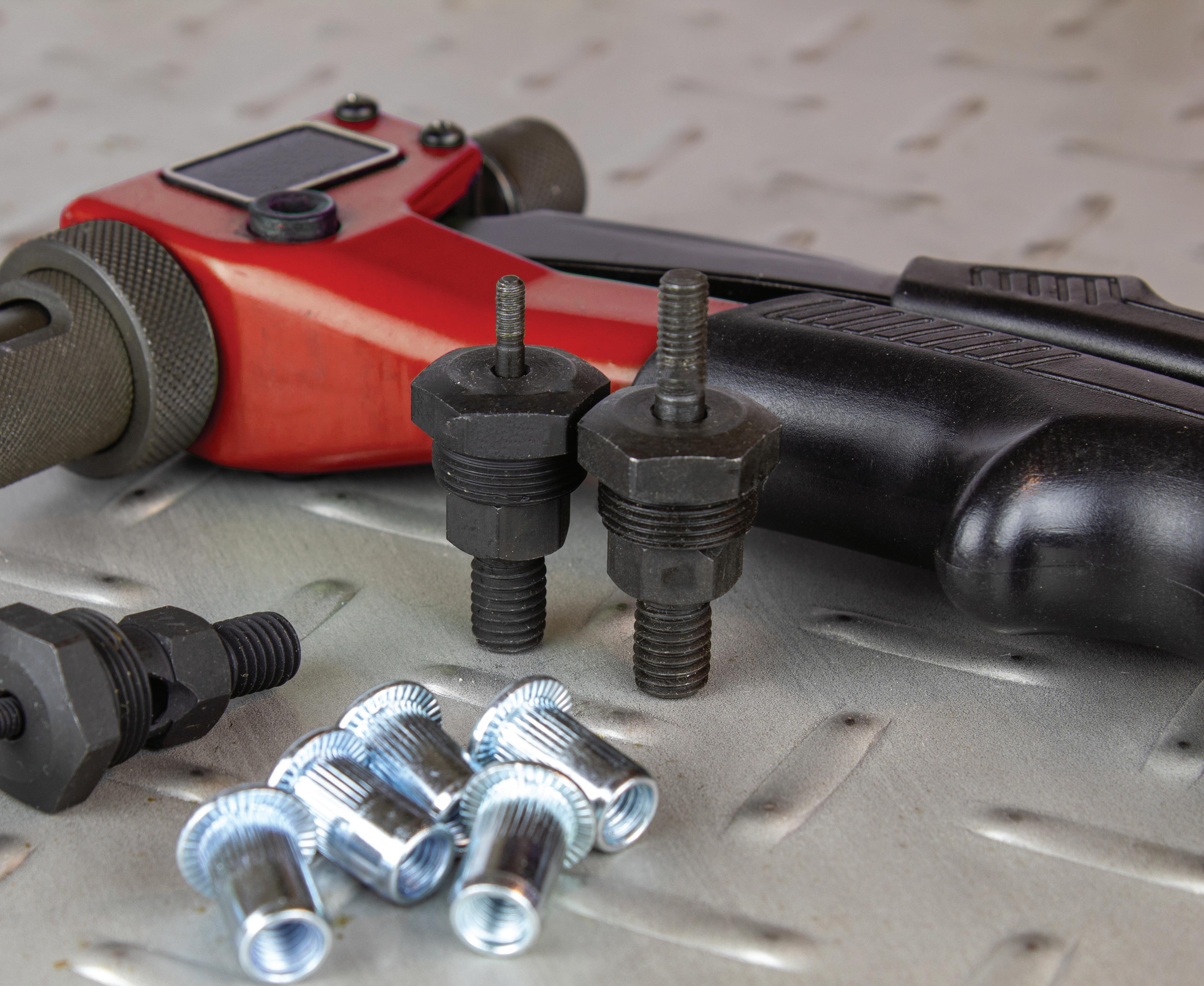
The condition of the tool will affect the pull-up force required for ideal rivet-nut installation. Keep the tool properly maintained, ensuring the head thrust bearing is lubricated.
Rivet-nut tool guidelines recommend using a high-quality socket-head cap screw (mandrel) that’s the correct length for the application.
Quality counts
The advantages of using high-quality rivet nuts:
• Provide a strong thread in thin materials that cannot be tapped
• Can be installed from one side of the workpiece, known as a “blind application”
• Can be installed in many kinds of materials, including steel, plastic, and fiberglass
• Ideal for use when easy disassembly and reassembly of products are necessary
• Once installed, additional components with threaded fasteners can be attached
DESIGN WORLD www.fastenerengineering.com December 2022 47
rivets
Types of rivet nuts
Ribbed or splined rivet nuts provide extra torque strength over standard rivet nuts with no spline. This is thanks to their knurled expansion surface. The splined body provides increased torque-to-turn resistance.
When installing the knurled part of the fastener, it bulges out and clamps the parent material on the blind side, offering excellent resistance to vibration and spinning. This is why knurled body “nutserts” are commonly used in the automotive industry with trucks and trailers — or with anything that might need a firm fix.
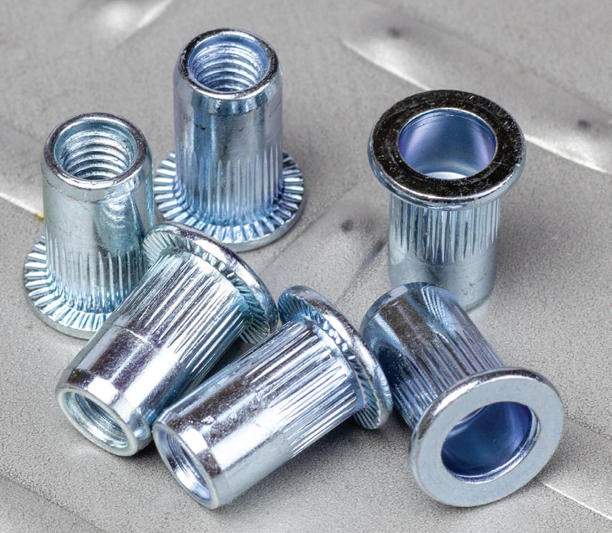
Overall, when choosing rivet nuts, the hardness of the material matters. Rivet nuts must be annealed to create a soft crimp.
How to install a rivet nut?
Several types of rivet-nut installation tools are available. Regardless of the tool, the process is the same:
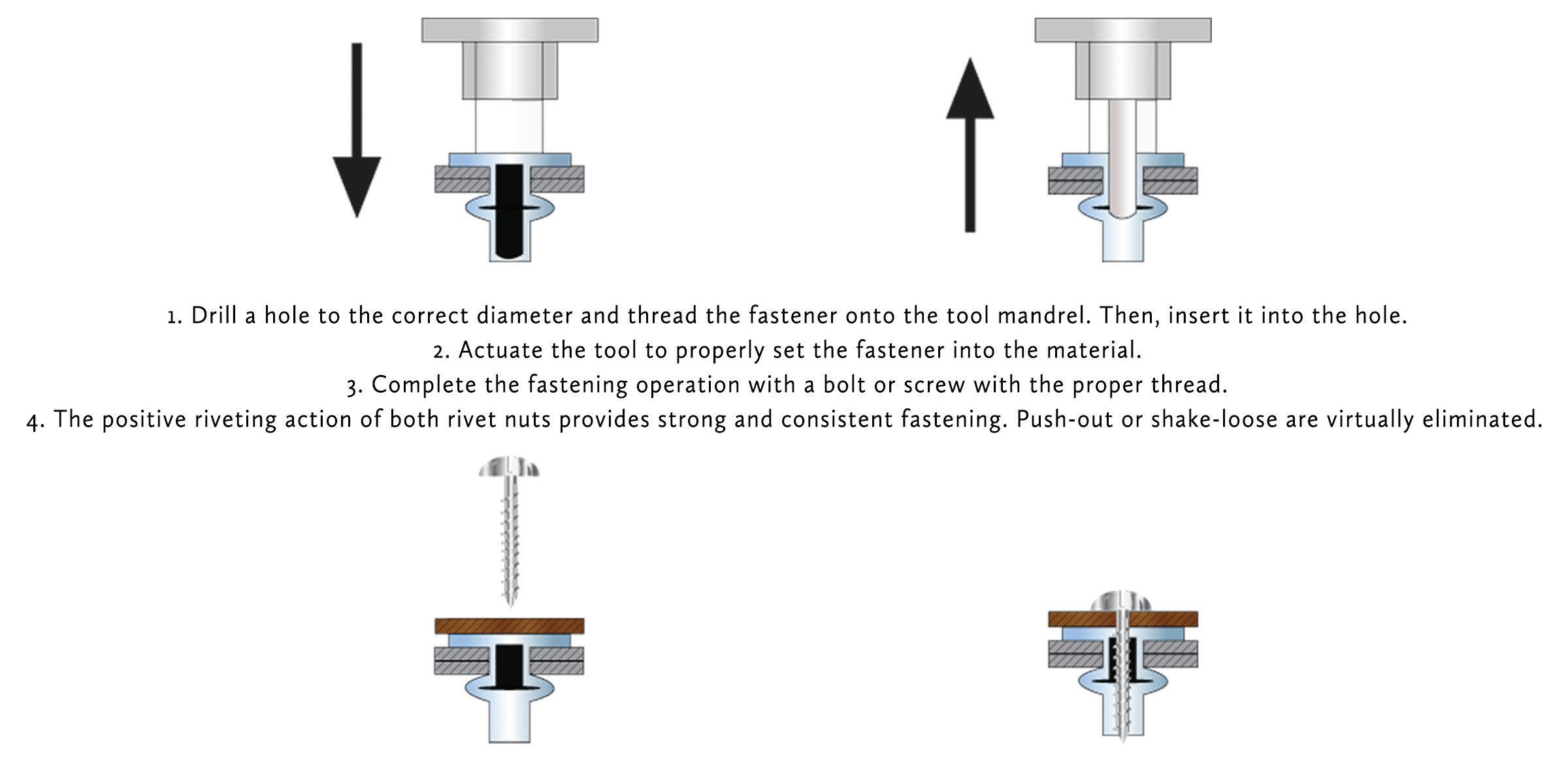
48 December 2022 www.fastenerengineering.com DESIGN WORLD
Rivet nuts, which are internally threaded fasteners, are also known as rivnuts, nutserts, threaded rivet nuts, blind rivets, and blind inserts.
MOTION CONTROL DESIGN GUIDES


The editors of Design World produce key technology content compiled in individual PDFs available for download.

CABLE CARRIERS
Motion control systems can vary from simple, straightforward single-axis direct-drive systems with little wiring to large and complex multi-axis robotic systems with a hornet’s nest of cables. This is usually where cabling, which was an afterthought, now takes center stage. This Design Guide details cable carrier subtypes as well as the different designs into which cable carriers integrate.
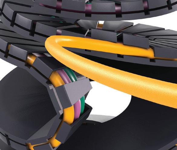
DC MOTORS
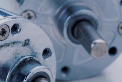


DC motors are motion components that take electrical power in the form of direct current and convert it into mechanical rotation. In this Design Guide, the editors of Design World detail the most common dc motor types as well common ways to quantify their output during the design-engineering process.
LINEAR MOTORS
Linear motors are one of the latest motion components to go mainstream for OEMs building moving machinery requiring high precision. This exclusive Design Guide reviews the functions and variations of linear motors for precision automation as well as their connectivity and configuration requirements.
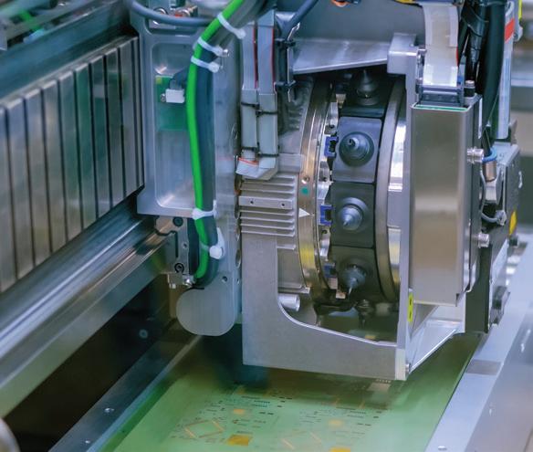
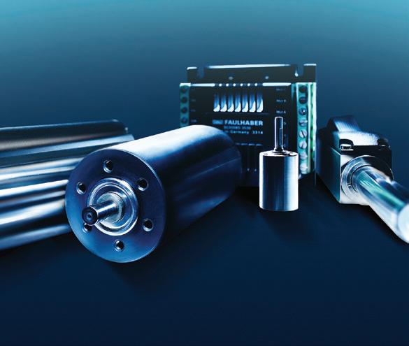
Find these and additional guides in our DESIGN GUIDE LIBRARY, bookmark this site as guides are added on an ongoing basis! designworldonline.com/design-guide-library

BROUGHT TO YOU BY:
SCREWS: COMMON SCREW-HEAD TYPES
What are the more common screwhead types?
Did you know the first known recorded use of screws occurred during the time of the ancient Greeks? These early fasteners were used in devices to press olives and grapes. From those humble beginnings, screws have become one of the most widely used pieces of manufactured hardware.
And today, these fasteners are available in several types, ranging in style, shape, size, and material. One of the top considerations when choosing the fastener for any application should be the type of screw head selected for use.
Here’s a brief overview of some of the most common screw head types, including their typical applications.
Socket-head cap screws are machine screws with a cylindrical barrelshaped head containing a hexagonal socket that fits a wrench for turning (instead of a slot or external hexagonal). These properties mean that socket-head cap screws are ideal for use in confined spaces. Socket cap heads are small, so the size of the component parts can be reduced, saving material costs. Smaller parts cost less to drill and tap, take less energy to drive, and weigh less than alternatives.
Button-head socket cap screws have a rounded, low-profile head containing a hexagonal socket that fits a wrench. These screws o er a flush profile, making them ideal for use in areas with little overhead or clearance and in confined spaces. They work best in light-duty applications such as in removable panels. Their wider bearing surface and high-tensile strength mean they’re also reliable in security applications.
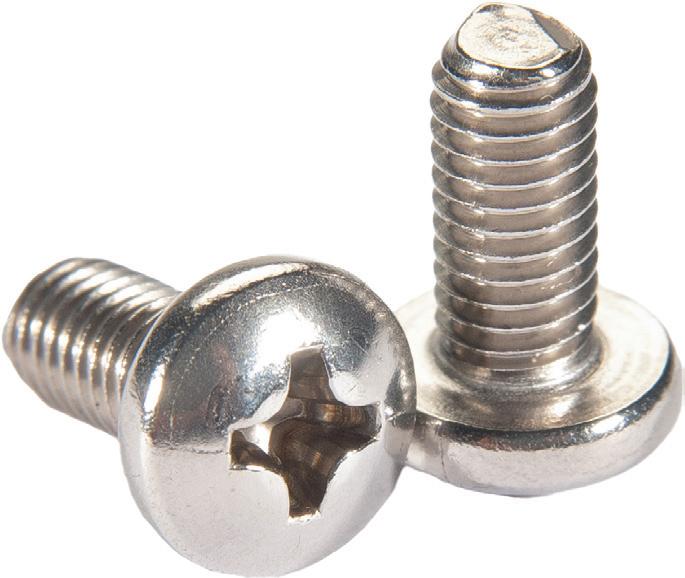
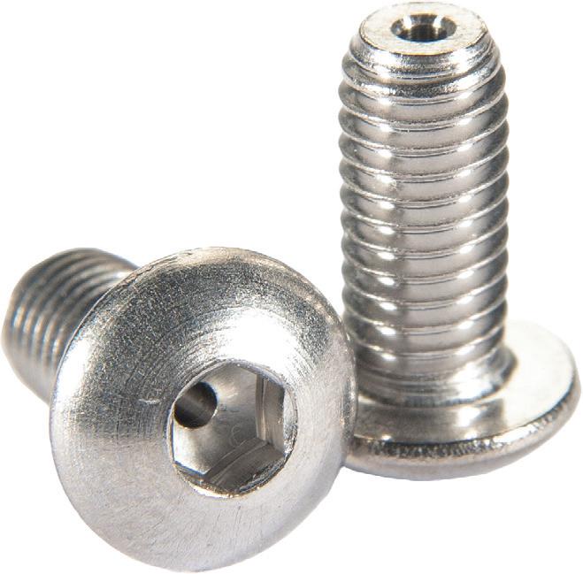
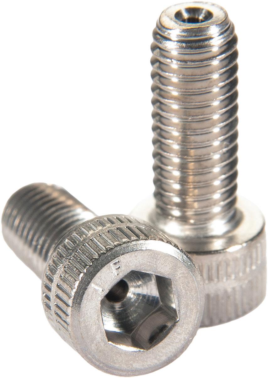
Socket set screws are typically used to secure an object within or against another object. They’re commonly used to secure a pulley or gear to a shaft, serving well in confined spaces. These fasteners are headless, meaning the screw is fully threaded and has no head projecting past the major diameter of the screw thread.
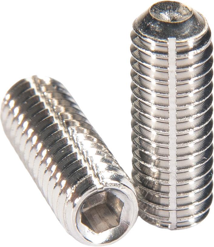
A socket set screw contains a hexagonal socket that fits a wrench instead of a slot or external hexagonal, and fastening these components requires no external clearance. The socket set screw passes through a threaded hole in the outer object and is tightened against the inner
Button-head socket cap screws
Socket-head cap screws

Pan-head Phillips screws
Socket set screws
50 December 2022 www.fastenerengineering.com DESIGN WORLD
Article courtesy of UC Components
object to prevent it from moving relative to the outer object. It exerts compressional or clamping force through the bottom tip that projects through the hole.
Flat-head socket caps feature a lowprofile and countersunk head. They’re ideal for applications requiring a strong fastener with a flush mount and are often used in applications that require moving parts to pass over a fastened area. Thanks to their ability to mount flush with the surface, flat-head socket caps are less apt to snag objects moving overhead. They’re produced with a socket drive that contains a hexagonal socket to fit a wrench for turning.
Flat-head Phillips screws have a lowprofile and countersunk head. They feature similar characteristics as the flat-head socket caps and are ideal for applications requiring a strong fastener with a flush mount. Flat-head Phillips screws have two partial slots crossed at right angles and are driven by a special screwdriver called a Phillips screwdriver. An advantage of the Phillips system is the screw and screwdriver, when used together, are self-centering. The x-shape of the screwdriver head fits into the similarly shaped slot of the screw, which is held in place so the force of the torque is centered naturally. This ensures the screw is driven straight.
Flat-head slotted screws are also ideal for applications requiring a strong fastener with a flush mount but are typically used in projects with moving parts that must pass over the fastened area. These screws are manufactured with a slotted head drive. Slot screw heads have a single horizontal indentation, referred to as the slot. The fastener head is driven by a “common blade” or flat-bladed (flat-head) screwdriver. The slot has a flat bottom, which is a good choice for low-torque, low-speed applications.
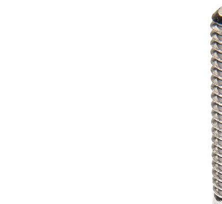
Pan-head Phillips screws take their name from the appearance of their head, which looks like an upside-down frying pan. This is a common head type of the non-countersunk used in machine screws. They have wide heads, a flat bearing surface, high vertical, chamfered, or curved sides, and a flat or slightly domed top. A pan-head Phillips head has two partial slots crossed at right angles, driven by a special screwdriver called a Phillips screwdriver. As mentioned, this system is selfcentering.
Fillister-head slotted screws have an oversized head, which is ideal for counterbored holes. These fasteners are like pan-head slotted screws but with greater side height. Fillister-head slotted screws are also compared to cheesehead slotted screws because they have cylindrical sides and a flat mating surface. But where the cheese-head slotted has a flat top, the fillister slotted screw head has a domed top resulting in an overall deeper head (these fasteners are sometimes called raised cheesehead slotted screws).
The fillister is manufactured with a slotted head drive. Slot screw heads have a single horizontal indentation referred to as the slot with a flat bottom, which is ideal for low-torque, lowspeed applications. The fastener head is driven by a flat-bladed (flat-head) screwdriver.
Hex-head screws, also known as hex bolts, are bolt fasteners with a sixsided hexagon head and an externally threaded body. The hexagonal profile enables easy wrenching while ensuring enough torque to the bolting joint. Hex bolts are typically used with a washer and hex-nut assembly or a tapped hole. Hex-cap screws allow for greater torque than conventional screws with a circular head.
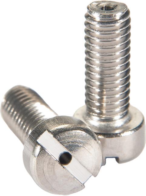
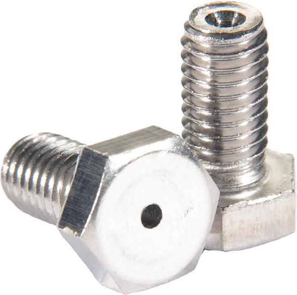
Twelve-point flange head-cap screws, also known as 12-point bolts, are an alternative head design for hex socketcap screws. The flange diameter and head height are designed to fit a range of applications and counterbored holes made for standard hex socket cap screws. The 12-point design permits this style bolt to be tightened with a 12-point socket wrench, which allows for the application of higher torque than a standard internal hex-drive socket head-cap screw. Another advantage: the 12-points have 30° between flats (as opposed to hex heads, which have 60°). This enables increased wrench flexibility (or placement) when manipulating the fastener.
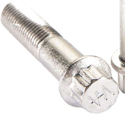
Twelve-point flange head-cap screws
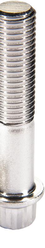
Hex-head screws
Fillister-head slotted screws
DESIGN WORLD www.fastenerengineering.com December 2022 51
seals
How to choose an O-ring for your application
Kim Keating, Director of Customer Success ZAGO Manufacturing Co.
An O-ring is a circular-shaped seal or gasket that’s made from an assortment of materials depending upon the application and the environment it will be used in. Sometimes called a packing or toric joint (because of its shape), it’s used to seal two working surfaces. O-rings are essential for protecting industrial machinery, electronic equipment, and a system’s inner components from wear and tear, including the detrimental effects of contaminants, seepage, or leakage.
Rubber O-rings are commonly used as they’re available in rigid and flexible materials with different strengths and tolerances. In the case of a sealing fastener, the rubber O-ring is engineered under the head of the screw or face of the nut or washer. Sealing fasteners provide a unique ability to protect conventional machinery and complex equipment with high-tech properties — thanks, to the inclusion of an O-ring.
Once torqued, the O-ring squeezes outward to form an unbreakable 360-degree seal that prevents gases and liquids from entering or exiting equipment operating in hazardous, treacherous, and/or pressured environments. The undercut groove ensures that the O-ring will not break or crack once installed, and the metalto-metal contact prolongs the life of the O-ring, which is not compromised under pressure.
With its impervious, unbreakable O-ring seal, the sealing fastener has the added benefit of protecting the environment from harmful contaminants. This can include disinfectants, oil, gas, humidity, dust, moisture, saltwater, or any debris or chemicals that can damage or destroy equipment. At the same time, it prevents equipment leakage of contaminants (i.e., acid leakage from lithium batteries) into the environment.
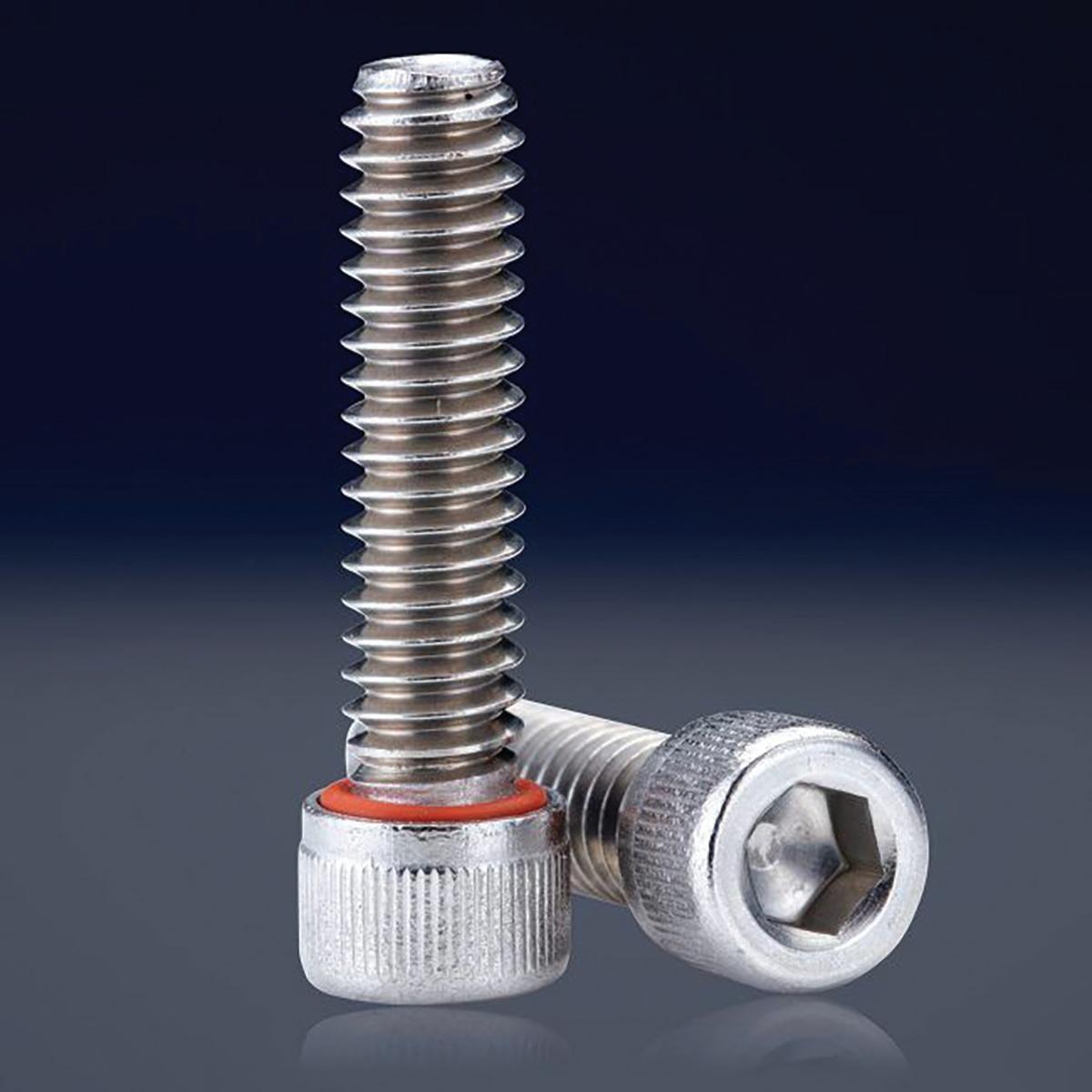
Equipment applications include hydraulic cylinders, water flow pumps, vacuums, and pneumatic medical devices such as pneumatic respirators.
Material choices
Choosing the ideal material for an O-ring is important to ensure reliability and longevity. This choice should be based on the application, including its exposure to contaminants, temperature range(s), and required standards.
For example, military-grade sealing O-rings that meet the requirements of the Military Standard MS3212/MS3213/
52 December 2022 www.fastenerengineering.com DESIGN WORLD
Sealing screws with O-rings engineered onto each fastener.
NASM 82496 and that are pressuretested to 1500 psi are available. This is also true of FDA-approved O-rings.
Below are six types of O-ring materials that work in various applications.
1. Silicone – an inert synthetic compound that’s available in a variety of forms (including rubber). Silicone is highly flexible and tolerates extreme temperatures without becoming brittle if exposed to cold. Silicone O-rings are used in several industries (such as aerospace, automotive, and electronics). This material is not recommended for dynamic seals because it lacks optimal solvent and oil resistance.
Temperature range: -80° to 400° F | -62° to 204° C
Shelf life: Unlimited
2. Buna-N – also known as Nitrile and NBR rubber, is one of the most costeffective and widely used elastomers. It offers a versatile resistance to water, saltwater, petroleum-based substances, hydraulic fuels, and alcohols. However, Buna-N is unsuitable for strong acids, weathering, and sunlight. It’s typically used in marine and offshore equipment applications.
Temperature range: -40° to 225° F | -40° to 107° C
Shelf life: 15 years
3. Fluorosilicone – a variation of silicone rubber that maintains high-temperature stability and durable mechanical properties. O-rings offer excellent fuel, oil, and solvent resistance and are commonly used in the automotive, aerospace, and military industries.
Temperature range: -67° to 350° F | -55° to 177° C
Shelf life: Unlimited
4. Fluorocarbon – active surfactants offering high chemical and thermal stability. Fluorocarbon O-rings can withstand high temperatures, harsh chemicals, greases, and fuels. They’re ideal for sealing aircraft engines and equipment in the automotive, transportation, and chemical industries. DuPont trademarked the wellknown Viton brand — a fluoropolymer elastomer and synthetic rubber compound that’s reliable in harsh environments.
Temperature range: -20° to 400° F | -29° to 204° C
Shelf life: Unlimited
5. EPDM – a synthetic rubber made of ethylene, propylene, and diene monomers. EPDM O-rings are extremely durable, providing outstanding ozone, heat, steam, and chemical resistance. They’re typically used to seal outdoor equipment, including weather and water-resistant applications and appliances.
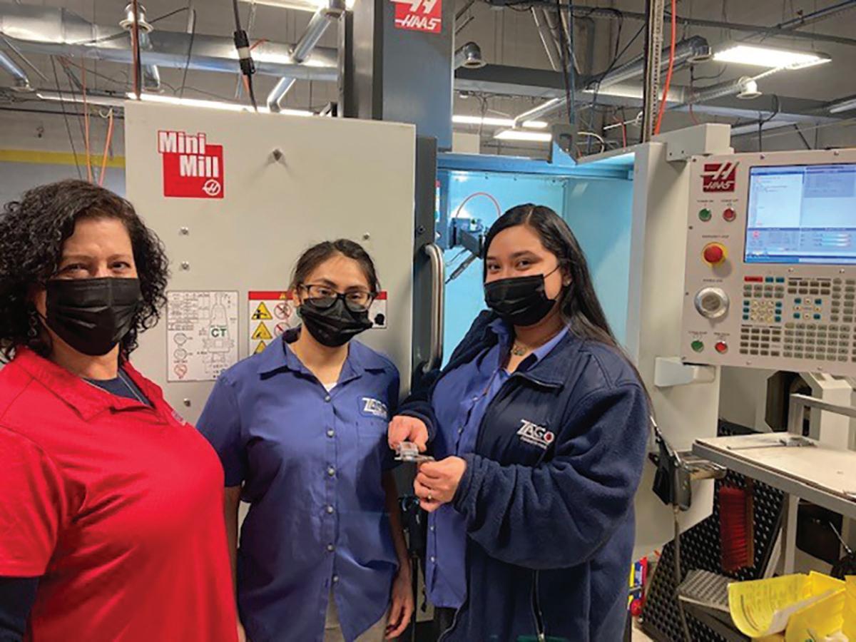
Temperature range: -65° to 225° F | -54° to 107° C
Shelf life: Unlimited
6. Chloroprene – a synthetic rubber better known by its trade name, Neoprene. This material has strong chemical stability and can be used over a wide temperature range. Neoprene O-rings are excellent at resisting ammonia, freon, oil, oxygen, as well as ozone and sunlight. They’re used in the automotive, HVAC, and refrigeration industries.
Temperature range: -40° to 225° F | -40° to 107° C
Shelf life: 15 years
DESIGN WORLD www.fastenerengineering.com December 2022 53
The ZAGO team inspecting parts after manufacturing.
supply chain Supply chain issues: How much is lost paperwork costing your company?
Lonni Kieffer Marketing & Customer Success, SmartCert
For hundreds of years, paper documentation has been used to deliver critical information, from receipts and prescriptions to certifications. This medium has faded from daily use.
The digital era is here. Email, software, and automated systems are commonplace. However, in the fastener industry, several organizations have yet to fully integrate digital processes or eliminate physical paperwork.
The problem is paper costs supply chains thousands of dollars, not counting the price of paper, ink, and printing, which undoubtedly adds to these expenses. Supply chains are most affected by paper documentation when this antiquated system fails.
Paper results in a lack of visibility, traceability, and efficiency. There’s a chance important documents could get lost, misplaced, or damaged. These risks are not as negligible as one might think. The disadvantages of losing vital records in the supply chain are vast and showcase why digitization is the ideal way forward.
Physical paperwork leads to:
• Increased risk of errors due to unreadable or missing documents
• Time wasted filing and organizing paper documentation (keeping employees from other essential tasks)
• An inability to quickly share documents between departments or remote parties
• Challenges in quick accessibility, particularly if products are recalled or fail
• Risks of delays in manufacturing or shipping
There’s also a negative environmental impact as paper copies are printed and eventually discarded. In fact, an average American office worker goes through as many as 10,000 sheets of paper each year.
Here are a few common scenarios that further outline the problem:
1. A distributor handles $30M of products yearly and scraps $180k because of related certification problems. The issue? The paperwork got lost, and the products could not be shipped due to the lack of certification required for compliance.
The certification process for fasteners — the inbound and outbound exchange of quality certifications – has changed little for many organizations, which still rely on paperwork. But paper results in a lack of traceability and efficiency. Fortunately, digital options are available.
For example, SmartCert automates the transfer of required documentation between companies, replacing paper and printing costs to reduce missing documents and promote sustainability.

54 December 2022 www.fastenerengineering.com DESIGN WORLD
2. A customer has installation problems and thinks they might have the incorrect inserts. The supplier must first find and review the certification. In the meantime, the parts are quarantined, with several employees affected. Instead of getting the job done, they’re spending time tracking down the paperwork and dealing with the stalled implementation.
When the supplier finally locates the correct documentation, it’s clear the inserts were provided by a different manufacturer and require a different installation process. Four employees spent a couple of hours each addressing this issue, costing the company in the hundreds.
3. A distributor sells parts to a customer but accidentally includes the wrong documentation. As a result, it’s necessary to quarantine the parts and send replacements. The new parts also include incorrect paperwork, leading the distributor to recommend an alternate source. This customer is now potentially lost for good.
In this case, the cost for the distributor includes:
• Labor of $1,500
• Red shipping and two lost sales for $120 + $2,400 + $2,500 = $4,920
• The loss of a customer at $66,000 ARR
Time is money. According to a recent Gartner study, it takes an average of 25 hours for lost documents to be recreated. This results in wasted time and money for a company.
Another report estimates that the average business spends $8,000 on paper and another $8,500 on filing and storage. This process also requires a dedicated file manager to ensure the organization of these documents, which can cost another $30,000 or more per year in labor.
Reducing lost paperwork
Many organizations still rely on legacy procedures. Some lack department time or insight to update these processes or fear investing in new technology. Awareness is key. Tracking the actual cost of paper and the risks involved can help supply chain organizations decide to change.
Going digital is not as challenging as it might sound. Ideally, the software or automated processes selected should allow your company to easily store, access, and edit certifications for your products in the cloud.

Additionally, the technology should:
• Establish the origin and complete history of a product as it travels through your supply chain
• Create a centralized repository for documents that are accessible to your teams
The consequences of antiquated processes
There are three costly ways companies lose money with paper certifications
1. Organizations lose 20 to 30% of revenue annually due to inefficient processes.
2. Approximately 40% of workers spend a quarter of their week on repetitive tasks.
3. Up to 40% of on-the-clock time is wasted searching for missing paperwork.
Advanced companies want to work with other well-run organizations. Adopting an automated solution gives team members the tools necessary to spend less time worrying about paperwork and more time improving the business.
• Share a unique QR code or email for each product to let any user in the chain access relevant and up-to-date certifications
• Search active and archived certifications
• Update certifications even if a product is already in transit, sitting on a warehouse shelf, or in use
Digital documentation creates a traceable supply chain in which all actors in a distribution life cycle can review a product’s history and legitimacy. As a result, your organization can significantly reduce the risk of counterfeit or defective products making their way to your customers.
DESIGN WORLD www.fastenerengineering.com December 2022 55
testing
Why should you test the fasteners you sell?
Rob LaPointe President & CEO, AIM Testing Laboratory
Hardness testing is one of the most common and informative fastener tests.
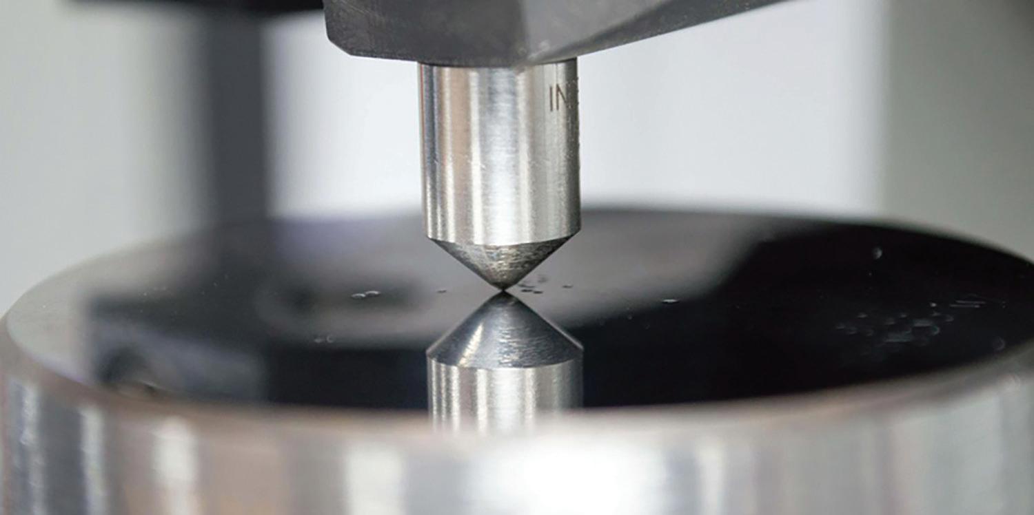
Fastener testing is integral to making or distributing a product with proven performance and reliability for its intended job. While not all fasteners require testing, it’s a good business strategy to understand the performance and quality of the products you sell. Let’s explore three main reasons for fastener testing.
The most important reason to test fasteners is that it’s required by the drawing or manufacturing specification. Most fasteners made to specific standards — such as ASTM A574 or ISO 898-1, grade 12.9 — have specific performance requirements such as chemistry, hardness, ultimate tensile, and yield tensile. Many products have additional requirements, including shear strength, proof load, and microstructure.
These tests and others are often required, with the results provided to a customer upon sale. Typically, the manufacturer is responsible for testing, performing it at an in-house accredited laboratory, or submitting the work to an accredited third-party testing lab.
After testing, the seller is given certified test reports showing the product tested with identifying information such as the part description, heat number, lot number, manufacturing specification, testing specifications, acceptance criteria, and test results.
56 December 2022 www.fastenerengineering.com DESIGN WORLD
Each report should be serialized and traceable by the laboratory and declared with a global conformance or nonconformance statement. To obtain a global conformance statement, all test results pertaining to the order must be conforming. If there are mixed conforming and nonconforming results, the test report should have a global non-conformance statement and give attention to the specific non-conforming results.
The second most important reason to provide fastener testing to customers (even if testing is not required) is to position your business as a provider of quality and reliable products. Providing certified test results, or at least making them available on request, means that you stand behind your products — and can provide proof of your assertions.
Additionally, this is an excellent profit strategy. There are enormous and often unaccounted-for costs when recalling or replacing faulty fasteners. Most profits are lost when a customer returns a product because it fails to perform. The fastener must be scrapped or reworked and then replaced.
In such cases, your company not only loses money on the cost of goods but also on the labor of servicing the replacement part, additional vendor costs, and administration and shipping costs. And then... there’s your reputation to account for.
Several of these expenses are not ascribed to a particular product replacement and show up in the profit and loss statement under general operation. Typically, a more detailed accounting indicates the financial penalty of shipping a faulty product.
It’s far less costly to submit fasteners for testing, gaining the assurance they’ll perform as anticipated before they’re sold. This also provides recourse should a customer experience a problem with the product. You’ll have the evidence and supporting documentation that the fastener meets or exceeds the advertised performance.
The third most important reason to test the fasteners you sell is to understand the process and product as you manufacture or perform secondary processing. In-process testing can provide insights into making gains in efficiency and eliminating waste from manufacturing. It can also help you catch mistakes before they are incorporated into a product.
It’s inefficient to find out that a product fails to perform as expected after completing the manufacturing or secondary processing of a product. Finding mistakes at this stage often requires undoing a process, fixing the issue, and then redoing the process. A significant amount of time and money is lost by not first testing and proving the process from start to finish.
There are many more reasons to test fasteners and fully understand the products you’re selling, but these three
are critical to a successful business. The fastener industry is interfaced with many different sectors, such as aerospace and automotive, where a reliable product delivered on time is critical. It’s worth the effort and expense to ensure that your industry contribution is received without issues, complaints, or concerns.
The most important reason to test fasteners is that it’s required by the drawing or manufacturing specification. An ISO 898-1, Class 12.9 hex cap screw is shown here.
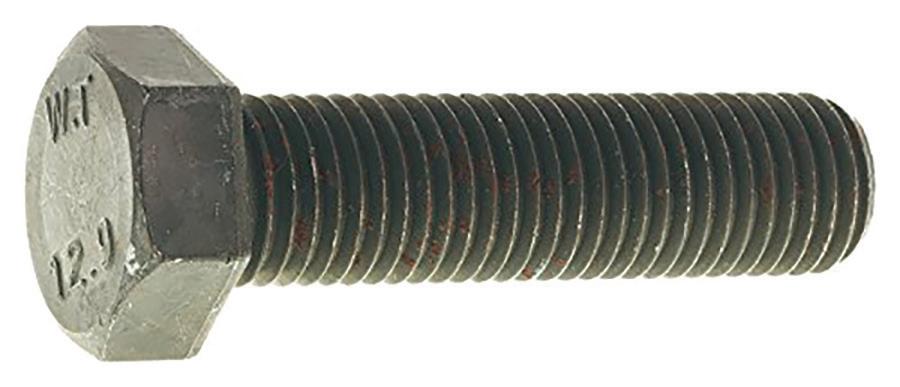
DESIGN WORLD December 2022 57
Some studies show energy savings of up to 95% by shifting from compressed air to motor-driven tools. This is leading to a new generation of fasteners and cordless installation tools, proving ideal for use at remote worksites.
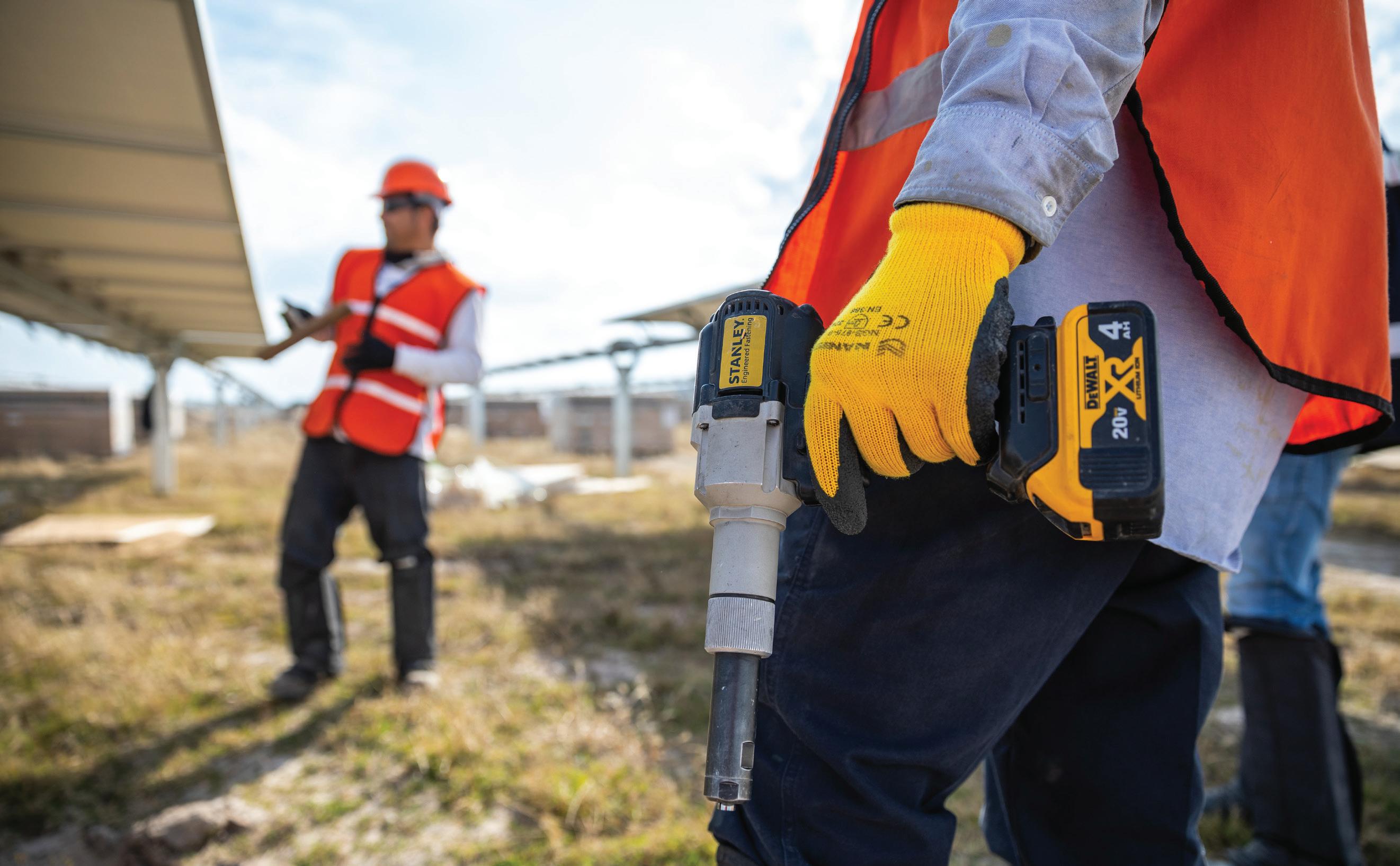
Why are battery-powered tools the preferred choice?
In the past, pneumatic tools promised a consistent level of power, justifying the costs of maintaining and monitoring the systems driving them. As energy costs rise and demands increase to improve operational efficiency, the cost-to-benefit ratio has diminished.
In fact, it’s been estimated that generating compressed air accounts for up to 10% of the total electricity consumption in many production facilities. Considering that on average 30% of the compressed air leaks out before getting to the end-users, operators are losing money every minute that a compressor is running.
In addition to the high volume of air wasted in air-driven production line systems, there are considerable adjacent costs associated with pneumatic systems. The hot, wet, oily
Article courtesy of STANLEY Engineered Fastening
air compressors produce must be conditioned to avoid contaminating downstream machinery. The oily condensate produced by compressors is also expensive to dispose of properly.
To ensure an acceptable level of efficiency in an air-powered system, proper maintenance is essential — adding further costs. Site-specific installations mean an independent electric source is required, and there’s always the risk of trailing air lines across public walkways.
While cordless tools are gaining traction in every market, the end-users of cordless equipment with the greatest impact are in the manufacturing industries. Commercial manufacturers use the same tools daily and require efficiency, reliability, and precision.
58 December 2022 www.fastenerengineering.com DESIGN WORLD TOOLS
Manufacturers are also experiencing demands to increase efficiency and capacity. Forward-thinking manufacturers are meeting these demands by upgrading tools and equipment, and this is where cordless handheld tools hold an advantage over air-driven ones.
Cordless fastener tools are currently representing one of the fastest-growing segments of the battery-powered tool market for several reasons and not just cost savings.
The decision to go cordless By some estimates, shifting from compressed air tools to motor-driven tools can result in energy savings of up to 95%. One study determined that pneumatic power tools use about seven to 13 times more energy than electric motor-driven power tools, and motor-driven tools are only becoming more efficient.
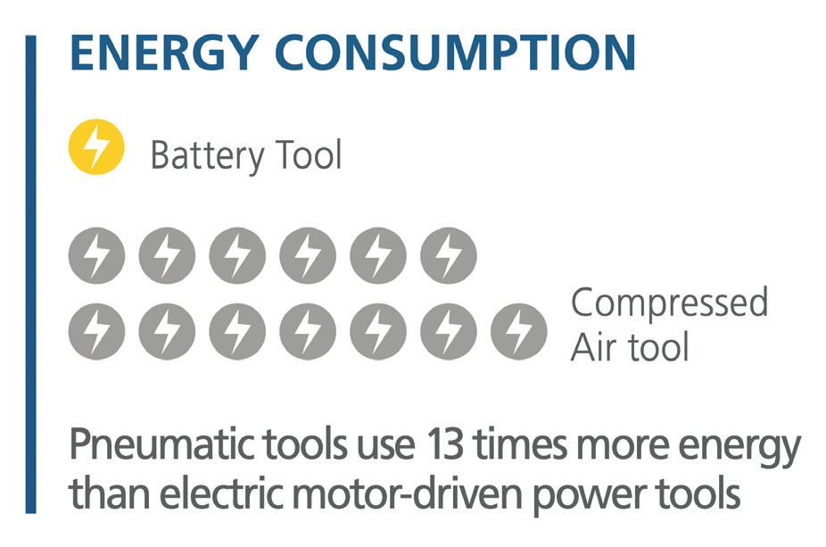
Cordless hand tools are more costefficient in manufacturing operations for a few reasons. The maintenance costs of motor-driven tools are negligible and they’re extremely energy-efficient. There’s no wasted energy like with air-driven systems. Companies also enjoy a lower incidence of workplace safety incidents caused by the hoses attached to air-driven tools, leading to fewer liabilities and risks of costly payouts.
The environment is another consideration. Cordless tools produce better working conditions than air-driven tools, from reduced noise production to improved air quality. Motor-driven tools are considered “cleaner” because they generate no oily by-products. Such oil-free operation means there’s no hazardous waste to manage, such as the oily wastewater caused by industrial pneumatic systems.
As environmental regulations change, compliance can be costly for production facilities using air-driven tools and require expensive equipment upgrades.
Cutting the cord
There are few places where user experience is more important than in the manufacturing industry, where reliability is essential and repeated tool use is commonplace.
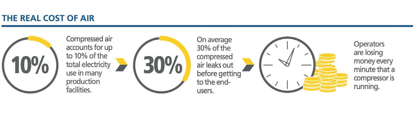
Two of the most compelling reasons users favor cordless tools are versatility and mobility. Cordless tools are untethered to a centralized air system, making them easy to take to remote sites (such as wind or solar energy projects).
The lack of a cord at a work site allows operators freedom of movement and increased ergonomic efficiency. The mobility and advanced features of battery-operated tools give operators the ability to be used to assemble multiple products on a single line.
Tool users are often subject to long hours of repetitive motions. Comfort and ergonomics are critical to worker longevity. Data from a McMaster University study comparing battery-operated and pneumatic tools suggests that using cordless tools reduces the demand on the forearms during use.
Research has also positively correlated hand-arm vibration from pneumatic tools with permanent hearing loss independent of noise exposure. Overall, battery-operated tools are the safer bet, reducing trips from cords and overuse injuries due to vibration.
Meeting demands
With demand for cordless tools in manufacturing at an all-time high, advances in tooling are providing new options.
The latest smart tools provide adjustable settings and performance-tracking features that make it possible to shift from one task to another with the same tool. Alerts let operators know when fasteners are inadequately tightened or torque specs are not met. Such error prevention features ensure every stroke or pull is precise and to spec, reducing manufacturing defects.
A new generation of cordless tools is designed to be “one battery fits all,” meaning that with the same battery, you can operate a fastening tool and a wide range of other tools, offering flexibility and convenience.
The newest generation of cordless tools is free of past limitations: they deliver more accurate torque, repeatability, and reliability than ever before.
Safety check
Before using a tool, first ask:
• Is this the ideal tool for the job? The wrong choice increases the risk of accidents and injuries.
• Is the tool safe to use? Does it have damage or any faults that could lead to mechanical hazards?
• Has the tool been maintained and tested? Power tools are typically used in harsh environments and should be regularly maintained.
• Is the environment safe for the use of the tool?
• Do you have the proper safety gear?
DESIGN WORLD www.fastenerengineering.com December 2022 59
training
Training and product knowledge lead to greater safety, accuracy, and confidence on the job. It’s important to know your fastener facts.
What are the answers to some of the most common fastener failures?
If you spent time in the fastener industry, you’re aware of the complex technology and engineering behind seemingly basic nuts, bolts, screws, and washers. Mechanical fasteners have been around for centuries, but that does not mean they’re failproof.
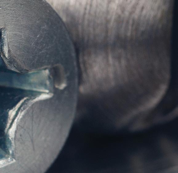
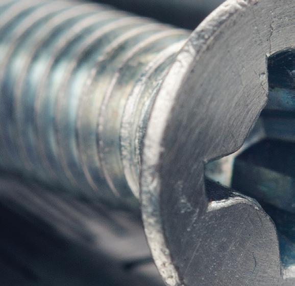
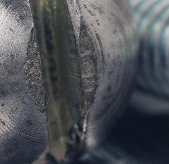
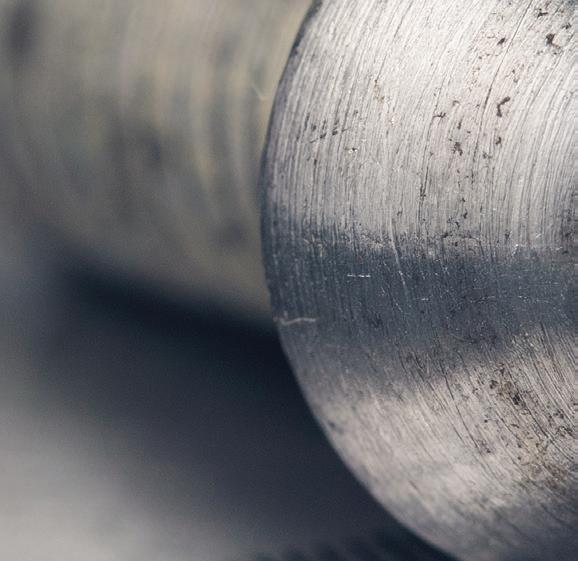

Fortunately, that’s where training comes in. The experts in the field guide us to better products, installation techniques, and overall application success.
One such expert was the late Joe Greenslade, an icon in the fastener industry. He taught mechanical fastener technology for 45 years, publishing more than 300 informational articles. He also served eight years as the director of Engineering & Technology at the Industrial Fasteners Institute, a trade organization for North American mechanical fastener manufacturers.
In 2015, Greenslade compiled a list of his most frequently asked fastener questions with answers — including a section dedicated to fastener failure analysis. As he once pointed out, determining the reason for the failure is critical: “It is worthless to propose failure remedies before a definitive ‘root cause’ of the failure is determined. A root cause needs to be discovered before an e ective remedy can be proposed.”
Here are a few of the questions he received with his answers to common fastener failures…
When a customer reports a fastener failure, what information should be gathered before trying to remedy the problem?
When a customer reports fastener failures, the information that should be gathered immediately before starting to try to remedy the problem includes:

• The exact part number

• The exact lot number
• The precise description of the failure and/or pictures of the failed parts
• Where the parts are used
• How the parts are driven and how tightening is controlled
• A sample of the broken and unused parts for analysis
When a customer complains about bolts and/or nuts vibrating loose, what is the likely cause?
The most likely cause of bolts and/or nuts vibrating loose is insu cient tightening. The most e ective remedy is to use correctly calculated higher tightening torque or better determine the correct tightening value experimentally using extra components.
60 December 2022 www.fastenerengineering.com DESIGN WORLD
Article courtesy of the Fastener Training Institute
|
Adobe Stock
When a bolt failure has a “necked down” area in the threads, what is the most likely cause of the failure…and the most likely remedy?
When a bolt failure has a “necked down” area in the threads, the most likely cause of the failure is tensile overload due to over-tightening, or the bolt has insufficient strength for the load requirements of the design. The most likely remedy is to reduce torque if the failure occurs during installation or increase bolt strength if failure is during product use. Check the tightening calculation and/or do a tightening experiment.
When the fracture surface of a failed bolt exhibits a “shoreline” pattern, what is the most likely cause?
When the fracture surface of a failed bolt exhibits a “shoreline” pattern, the most likely cause of the failure is fatigue. The most likely remedy is to increase the tightening value.
When a bolt or screw has an intergranular fracture surface immediately under the head or at the first unengaged thread of the bolt or screw, what is the reason?
When a bolt or screw has an intergranular fracture surface within 48 hours of installation, the most likely cause is hydrogen embrittlement (see FTI note below). This can be remedied by baking the parts at 400° F for 14 or more hours. Or better yet, change to a finish not subject to hydrogen embrittlement.
What if this same failure occurs weeks or months after installation?
When a bolt or screw has an intergranular fracture surface immediately under the head or at the first unengaged thread of the bolt or screw weeks or months after installation, the most likely cause is stress corrosion — also called environmental hydrogen embrittlement failures.
This can be remedied by using fasteners with a core hardness of less than HRC 39. Otherwise, consider paint, coating, or a method that protects fasteners from the moist environment. For example, redesign the joint to prevent fasteners from being in moisture or avoid the use of dissimilar materials in the joint construction.
What is the critical hardness above which hydrogen-induced failures can occur?
HRC 39 is the critical hardness above which hydrogen-induced failures can occur.
Why should designers avoid applications where dissimilar materials come in contact with one another?
And what are the two approaches that can be taken to avoid failures when dissimilar materials must be mated with one another?
Designers should avoid applications where dissimilar materials come in contact with one another to avoid potential galvanic corrosion.
The two approaches that can be taken to avoid failures when dissimilar materials must be mated with one another is to select fastener materials that are closer to the component materials on the “galvanic scale,” and/ or coat/paint the joint to keep moisture away from the joint.
FTI note… Galvanic corrosion refers to corrosion damage induced when two (or more) dissimilar materials are brought into electrical contact under water.
For additional FAQs from Greenslade: https://tinyurl.com/FastenerFacts

Meeting standards is critical to ensure a safe and reliable assembly. Organizations, such as the American Society of Mechanical Engineers (ASME) and ASTM International, support the industry with the latest codes and standards for testing, materials, and engineering.
FTI note… Hydrogen embrittlement (HE), is a permanent loss of ductility in a metal or alloy caused by hydrogen in combination with stress — either applied externally or from internal residual stress. Generally, HE is classified under two broad categories based on the source of hydrogen: internal hydrogen embrittlement (IHE) and environmental hydrogen embrittlement (EHE), according to the “Fundamentals of Hydrogen Embrittlement in Steel Fasteners,” by Salim Brahimi.
DESIGN WORLD www.fastenerengineering.com December 2022 61
The late Joe Greenslade, an industry expert in the fastener sector.
What are the advantages of using hardened and unhardened flat washers?
Michael Eusanio Applications Engineer, Optimas Solutions
It’s common to assume a single part is stronger than an assembly of parts. However, fasteners can ensure the strength and reliability of a product, given certain considerations.
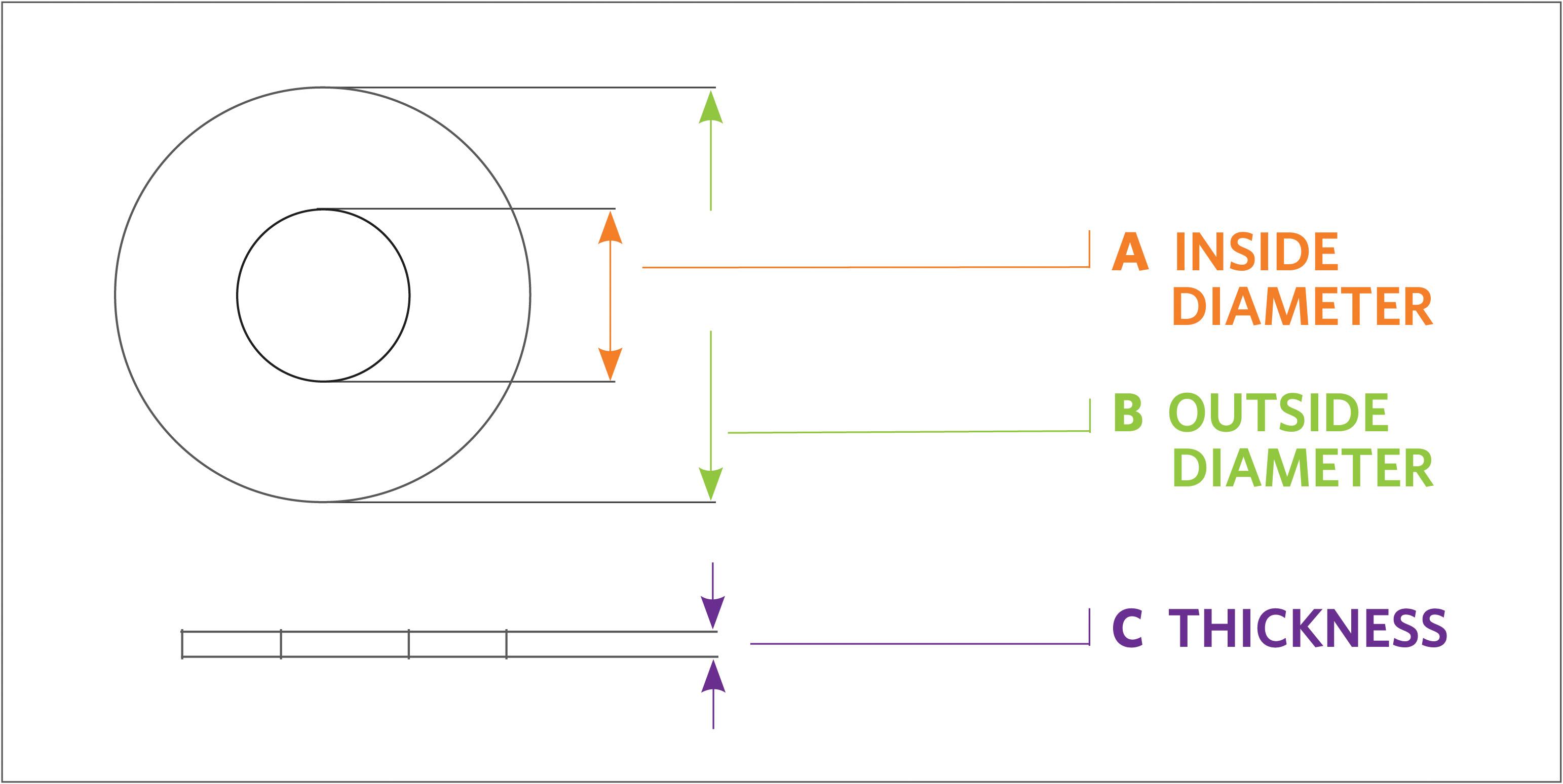
For example, by tweaking the type of fastener material, size, or other specifications, manufacturing engineers can resolve torque, weight, stability, and durability concerns with no change to assembly or procedure.
One such tweak: using hardened steel washers. Replacing standard washers with hardened steel means fasteners
can be more reliably tightened. In fact, research shows these fasteners can be torqued with up to 50% higher clamping pressures, resolving bolt failure issues without making significant changes to the product design.
Mild steel is a generic low-carbon material used in typical washers and fastening systems. In comparison, unhardened steel is any steel material that has not undergone the hardening process. Understanding the difference between mild, low-carbon, and unhardened and hardened steel washers
can make a difference in an engineer’s part design. The result: fastener assemblies that are more reliable, durable, and longer lasting.
Hardened vs. unhardened flat washers
Hardened flat washers are designed for assembly with a Grade 5 or higher strength bolt between the bearing surface of the fastener and the part to which it’s attached. These washers are carbon steel and can be throughhardened to Rc 38-45 or carburized (case hardened) to a minimum depth of
62 December 2022 www.fastenerengineering.com DESIGN WORLD
WASHERS
The top and side views of a hardened and unhardened flat washer.
The specifications of hardened and unhardened flat washers
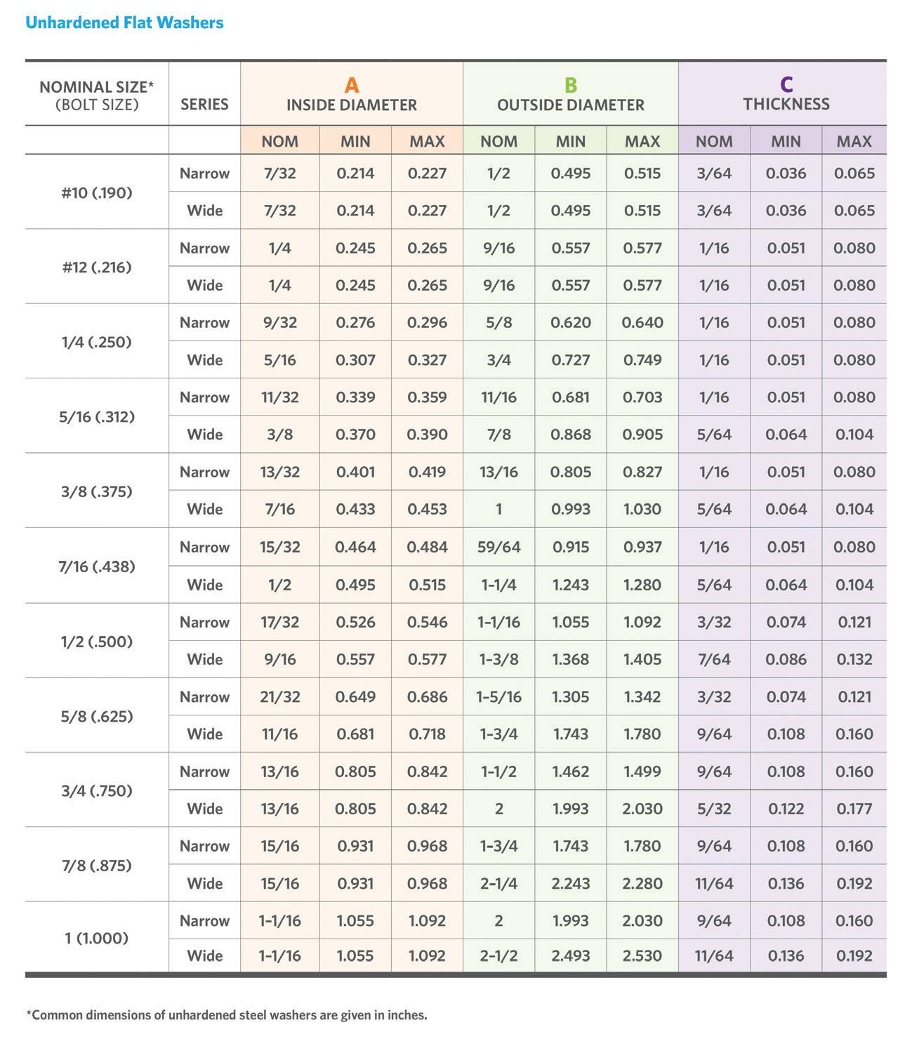
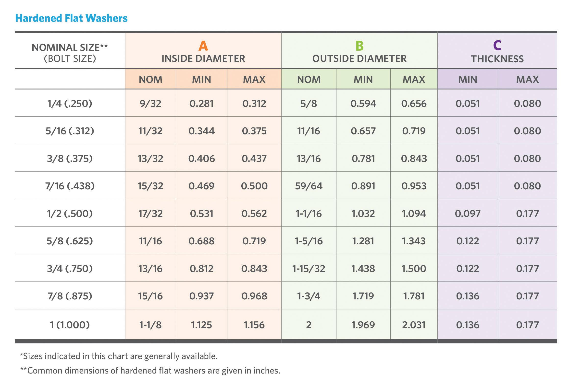
.015“. They have a surface hardness of 37-45 Rc with a minimum core hardness of Rc 30.
Unhardened flat washers are designed for assembly with Grade 2 or lower strength bolts or tapping screws between the bearing surface of the fastener and the part to which it’s attached. Narrow (SAE) and wide (USS) flat washers are available for specification, depending on the required outside diameter.
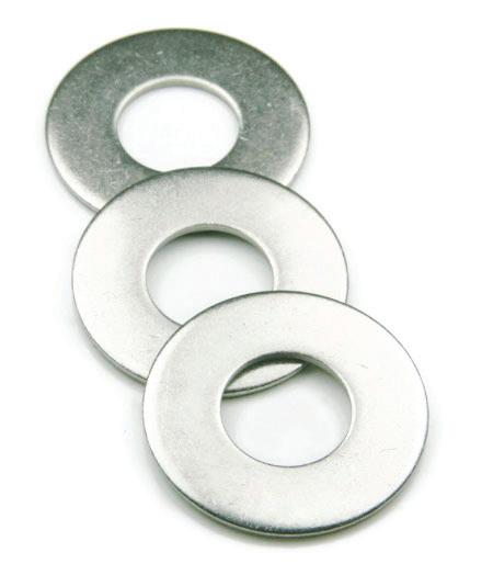
The benefits
Hardened and unhardened flat washers offer several advantages in a fastener assembly, including:
• Protecting the mating surface from damage during assembly
• Improving the stress distribution on the mating surface
• Spanning larger clearance holes
• Providing a consistent bearing surface between the mating surfaces for torquing
The standards
In hardened and unhardened flat washers, the dimensional characteristics are covered by ANSI B18.22.1*, and the mechanical properties are covered by ASTM F844. Both ANSI (the American National Standards Institute) and ASTM (formerly the American Society for Testing and Materials), develop and oversee technical standards.
Understanding the effect a washer has on the entire fastener solution and assembly is critical before deciding on the ideal match for an application. This includes the fastener material and the tool and torque used during installation.
A washer can be instrumental in adjusting torque — ultimately adding more strength and longevity to an assembly.
DESIGN WORLD www.fastenerengineering.com December 2022 63
welding: materials
What is micro-welding and why is laser an ideal fit?
Laser welding does not generate particulates. This is especially important in the microfluidic systems used in many biomedical applications where narrow pathways could become contaminated or clogged by debris.
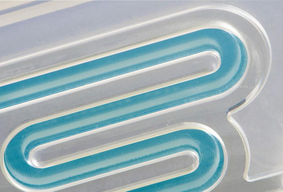
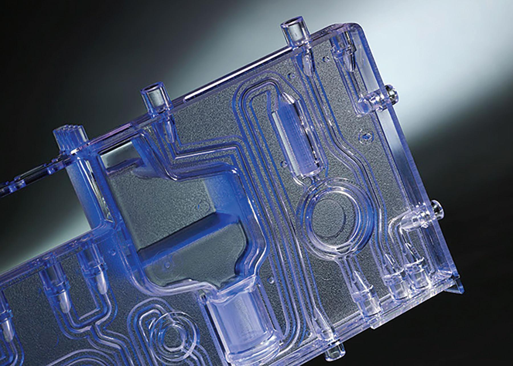
Several of today’s advanced applications involving plastic components are also some of the smallest. Developing compact devices that contain sensors and other tiny, delicate internal elements is a high priority for designers and manufacturers, particularly in the automotive and electronics industries. The same is true in medical devices used for in-vitro diagnostics (IVD), vital-signs monitoring, and injection and inhalationtherapy applications.
There’s a lot of complexity — geometric and electronic — inside these small devices as manufacturers attempt to offer more features without increasing
size. Product quality, durability, precision, and aesthetics are also critical objectives. So, what is the ideal way to assemble these small yet significant plastic devices?
Many designers rely on microwelding laser technology as an alternative to conventional fasteners or adhesives. The precision and controllability of laser welding make it ideal for meeting the challenge of creating small and reliable joints. Such joints can be as short as a few tenths of a millimeter and as narrow as 100 μm in parts with a surface area the size of a postage stamp.
Choosing laser
There are several reasons why a laser is ideal for micro-welding, including the following.
Control. It’s possible to accurately control the power dissipation within the weld by varying the power of the laser source. In Through-Transmission Infrared (TTIr) laser welding, radiation travels through an IR-transparent part and heats the surface of the mating part, but only to a specified depth. Heating is precise and highly localized to the area touched by the narrow IR beam. This is critical for parts with small sections and thin walls,
64 December 2022 www.fastenerengineering.com DESIGN WORLD
Emma Wood, Global Product Manager, Emerson
All Images courtesy of Emerson
and the resulting welds are nearly as strong as the parent material(s).
Particulate-free. The laser-welding process is non-intrusive, and parts typically exhibit excellent cosmetic properties, which are essential for small parts where a minor aesthetic flaw is obvious. Also, there’s no frictional motion between the parts, so the welds are entirely free of particulates. This is critical for components with narrow pathways (such as micro-fluidic systems used in many biomedical applications), which risk contamination or clogging from debris during the welding process. The precisely controlled heat and pressure are beneficial, minimizing the risk of polymer displacement or channel collapse.
Design flexibility. The versatility of the laser-welding process makes it ideal for assembling extremely small components. Weld lines that span different three-dimensional spatial planes can be problematic with other bonding methods but are joined easily with lasers. Lasers can bond several materials, such as thermoplastic elastomers and other soft plastics, including combinations of dissimilar materials. Intricate internal welds are also possible.
Gentle. Several small products — such as earphones, smartwatches, or automotive sensor packages — contain delicate electronic components that are easily damaged during assembly. Microwelding bonds sensitive electronic and mechanical without damage because there’s little movement of the parts during joining and no excitation or vibration. The welding machine parts make no contact with the weld line. Force is applied to hold the parts, but at non-critical areas or surfaces, protecting them from damage.
Speed. Laser welding is virtually instantaneous, with reliable bonding in as little as 0.5 seconds, so it suits the high-volume production of small components. Unlike welders that focus laser light on only a small portion of the weld line at a time, simultaneous laser welding is an option that heats the entire weld surface at one time — dramatically reducing cycle time without compromising quality.
There’s increasing demand for smaller and more intricate plastic components, often housing sensitive electronics, in several important markets. Manufacturers are looking for systems that deliver strong, clean joints in a highly compact package that suits installation in automated process lines. Such a solution is found in laser welders that specifically target micro-welding applications.
There are solutions that address the challenges of micro-welding applications involving small and intricate plastic components. For example, the Branson GLX-1 laser welder is Industry 4.0/ IIoT (industrial internet of things) capable, delivering actionable operational data via OPC-UA interfaces.
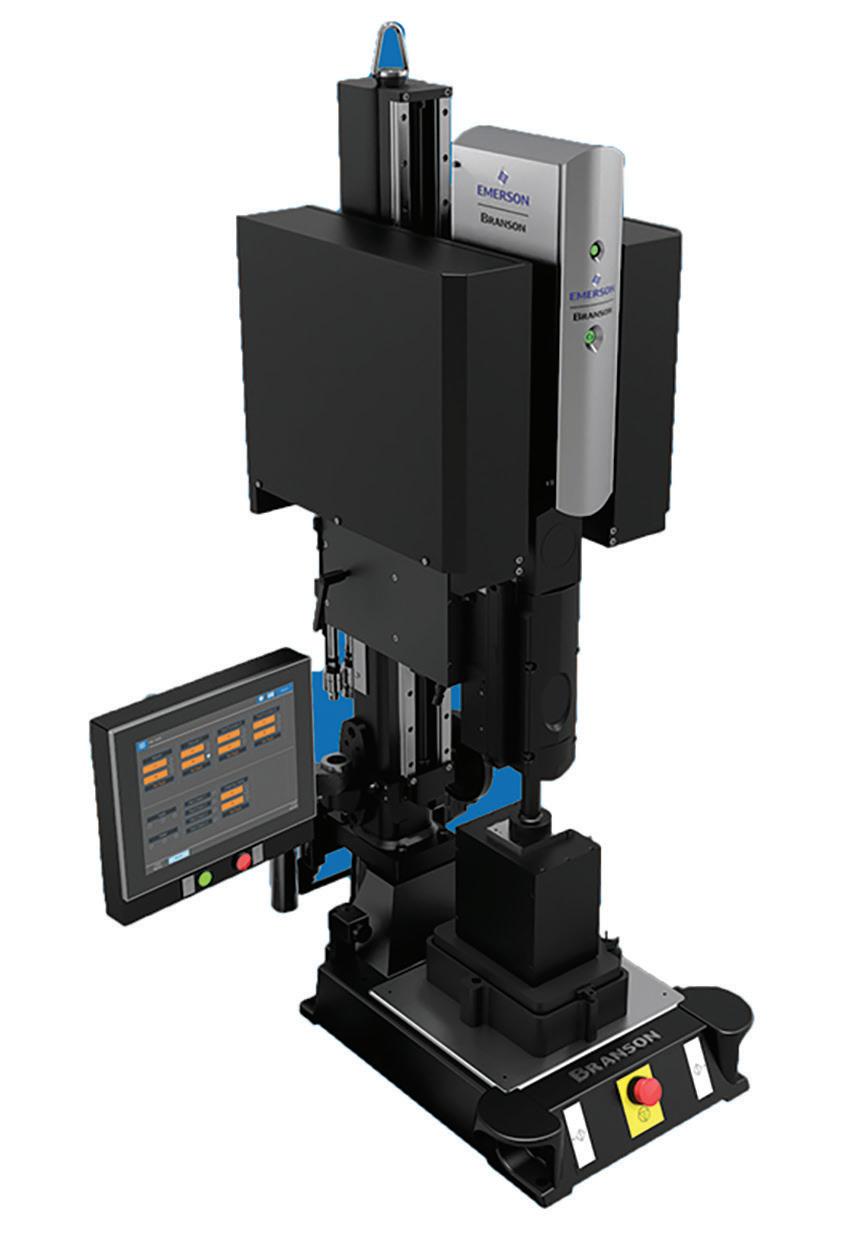
DESIGN WORLD www.fastenerengineering.com December 2022 65
Branson metal and plastic welding technologies from Emerson support manufacturing efficiency and enable innovative new product designs in such markets as medical, automotive, electronics, packaging, and others. Emerson invented ultrasonic plastic welding 75 years ago and has since expanded its range of joining technologies to include vibration, laser and infrared plastic welding systems, and heat-staking equipment. Digital controls ensure increased precision and quality, while providing data for process optimization and regulatory compliance. Branson application development laboratories help customers shape brilliant ideas into workable designs, bringing ready-to-manufacture products to market, quickly and sustainably. The global Emerson aftermarket network delivers expert maintenance, reliability, and performanceenhancement services.
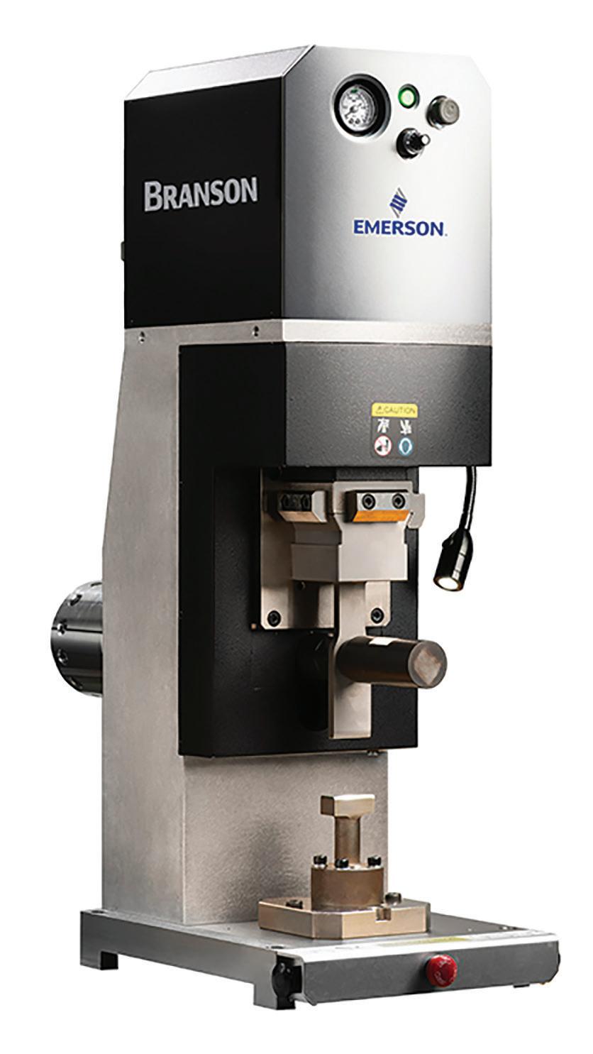
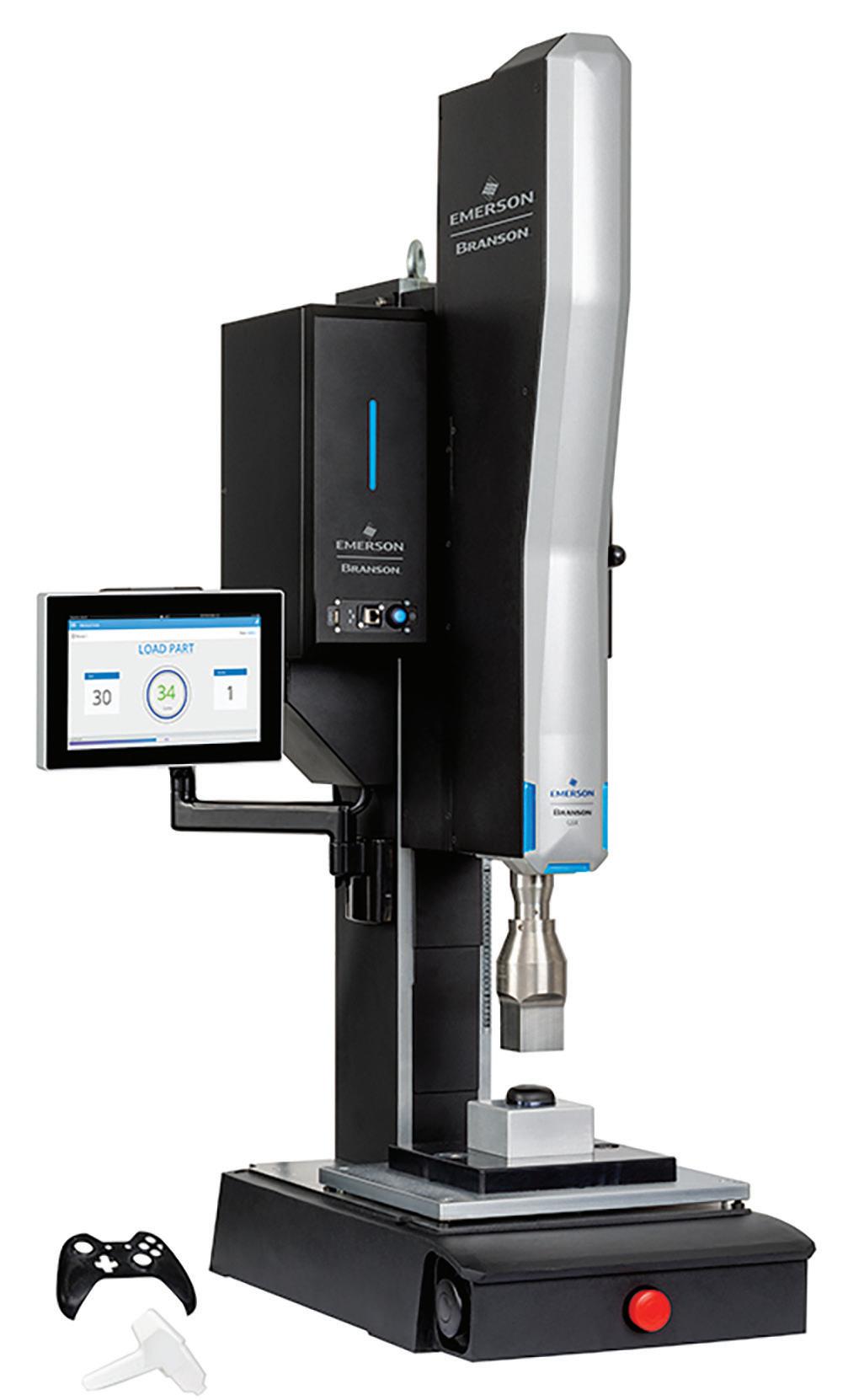
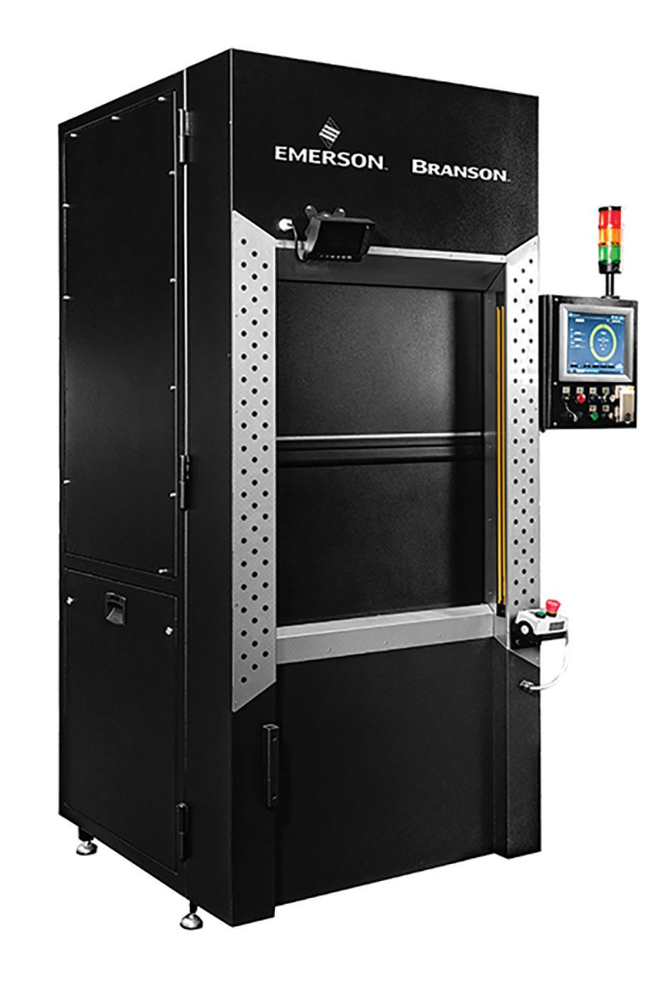
Vendors in the fastener industry


Emerson 120 Park Ridge Road Brookfield, CT 06804


Phone: 203-796-0400 Branson.Info@Emerson.com www.emerson.com/branson
2022
Emerson
ADVERTISEMENT 66 December 2022 www.fastenerengineering.com DESIGN WORLD • • • • • • • • • • • • • • • • • • • • • • • • • • • • • • • • • • • • • • • • • • • • • • • • • • • • • • • • • • • • • • • • • • • • • • • • • • • • • • • • • • • • • • • • • • • • • • • • • • • • • • • • • • • • • • • • • • • • • • • • • • • • • • • • • • • • • • • • • • • • • • • • • • • • • • • • • • • • • • • • • • • • • • • • • • • • • • • • • • • • • • • • • • • • • • • • • • • • • • • • •
Vendors in the fastener industry


Smalley
Founded over 100 years ago, Smalley has evolved to become the world leader in the manufacturing and development of Retaining Rings, Spirolox® Retaining Rings, Constant Section Rings, and Wave Springs. Smalley has led the way in introducing state-of-theart products and continues to lead the way in innovations for the future.


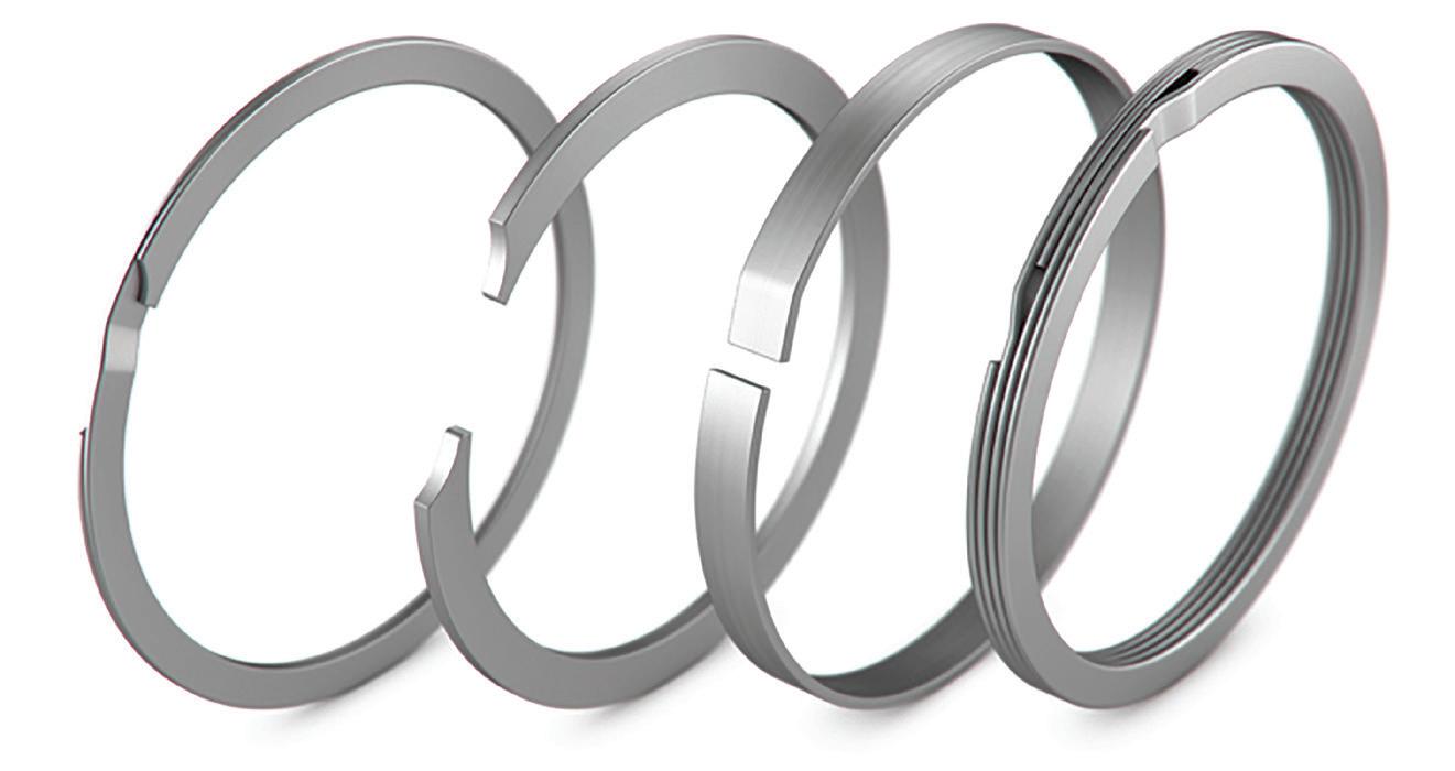

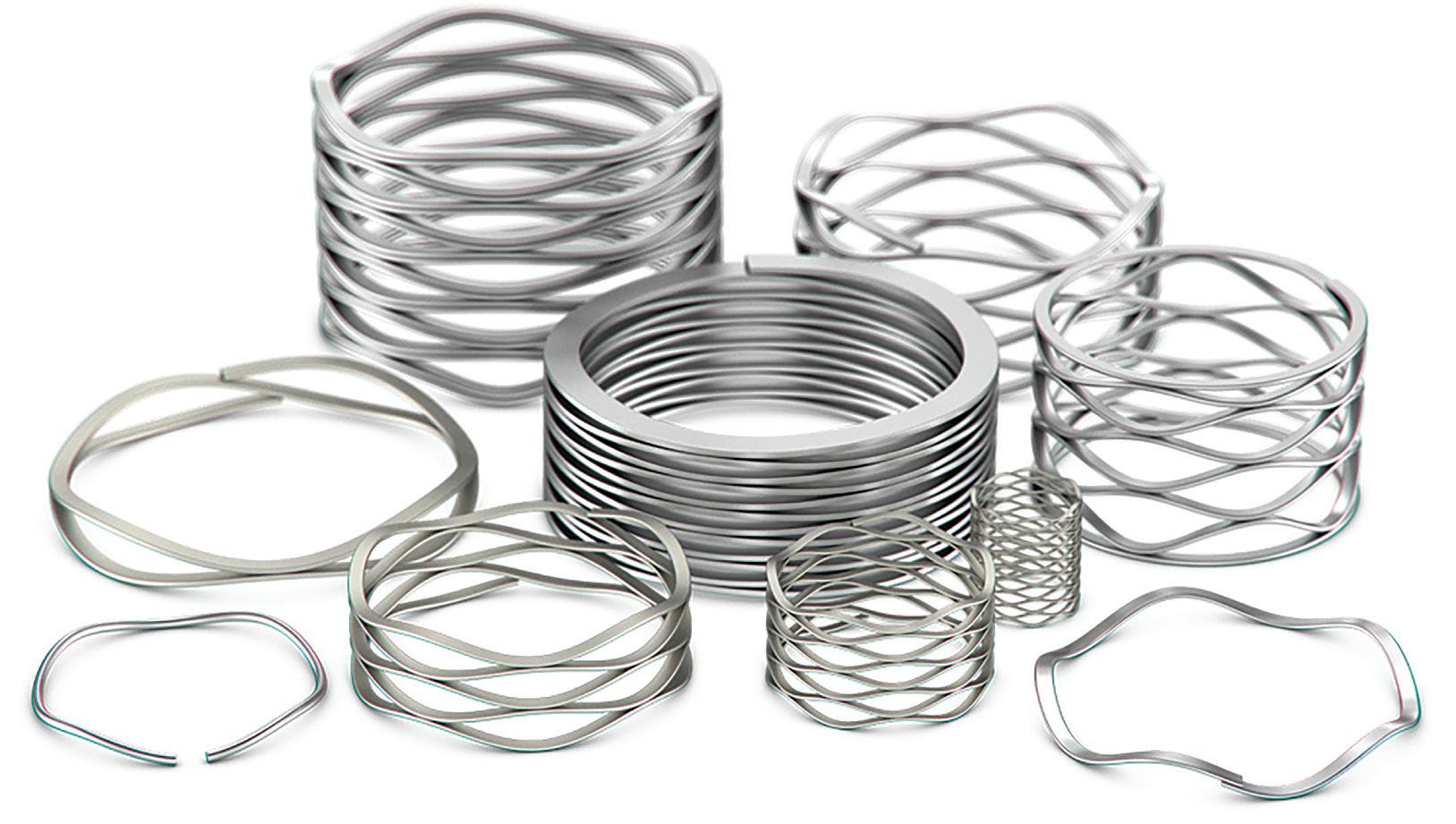
Smalley stocks over 10,000 standard parts across 30 configurations and 400 sizes. If a standard part doesn’t meet your requirements, you’ll work with our team of over 30 industry-specialized engineers to quickly create an economical custom part in the material of your choice, all without new tooling. Prototype or production volume, our No-Tooling-Charges™ manufacturing process meets the design flexibility your application, budget, and timeline requires.
While all of our manufacturing is made in our U.S.-based 300,000 ft2 facility, our global network of offices, engineers, and distribution partners allows you to receive parts and support from anywhere in the world quickly. Smalley’s dedication to quality and manufacturing excellence has earned us multiple service and quality awards and the trust of OEMs worldwide.
Smalley


555 Oakwood Road Lake Zurich, IL 60047


Phone: +1 847 719 5900 Email: info@smalley.com smalley.com


DESIGN WORLD www.fastenerengineering.com December 2022 67 2022
ADVERTISEMENT
Selecting the Optimal Washer
Flat: Generally used for load disbursement
Tab/Lock: Designed to effectively lock an assembly into place
Finishing: Often found on consumer products
Wave: For obtaining loads when the load is static or the working range is small
Belleville: Delivers the highest load capacity of all the spring washers
Fender: Distributes a load evenly across a large surface area
Shim Stacks: Ideal for simple AND complex applications
Boker’s Inc. 3104 Snelling Avenue Minneapolis, MN 55406-1937 Phone: 612-729-9365 TOLL-FREE: 800-927-4377 (in the US & Canada) bokers.com
J.W. Winco, Inc.
Spring Loaded Devices from JW Winco
When you need to align, hold, or latch different parts of equipment together, you need a spring loaded device.These locking systems are designed to facilitate repetitive positioning operations on machines and equipment or parts undergoing machining. Spring loaded devices create a secure connection with limited play. JW Winco has many different versions and types for your application requirement.
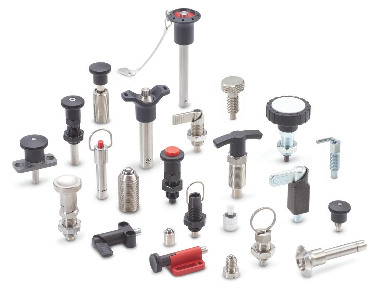
Check out www.jwwinco.com to find out more!
J.W. Winco, Inc.
Phone: 800.877.8351 sales@jwwinco.com www.jwwinco.com
68 December 2022 www.fastenerengineering.com DESIGN WORLD
Wide variety of spring to meet your innovation needs
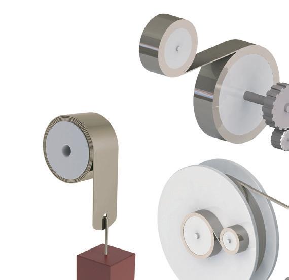
When it needs a specific spring to empower mechanical function of your product for best performance, such as Tensioning & Loading, Counterbalancing, Retrieving & Returning, Drive Motor, you are welcome to contact design engineer of Ming Tai Industrial Company for best solution. Based on 60 years manufacturing experience of steel strip spring, well experienced engineers of Ming Tai Industrial Company are capable to provide you with the best solution to meet your innovation needs.
Check out www.powerspring.com.tw for more interesting innovation stories!
Ming Tai Industrial Co., Ltd. No. 250, Sing Jhong Road Tamsui, New Taipei City 251 Taiwan Phone: 886-2-26228651 Fax: 886-2-26220202 E-mail: mtis@powerspring.com.tw
NBK Acquired Solid Spot’s Plastic Fastener Business and Expanded Lineup
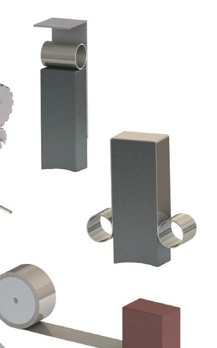

NBK is a manufacturer of Specialty Screws including Plastic Fasteners. In this April, NBK acquired Solid Spot LLC’s plastic fastener business and then, more various product lineup are available such as PEEK, RENY, PC, PVDF, PTFE, POM, etc.
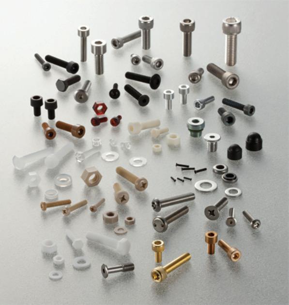
NBK manufactures not only plastic screws but also low profile (low head), miniature size(less than M3), vacuum application, anti-galling, chemical resistance, non-magnetic, and more.
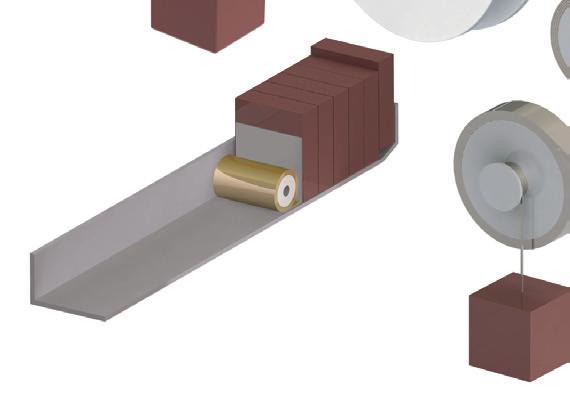
Flexible customization is available.


NBK America LLC

307 East Church Road, Suite 7 King of Prussia, PA 19406
Phone: 484-685-7500 https://www.nbk1560.com/en-US/
DESIGN WORLD www.fastenerengineering.com December 2022 69
A family-owned business since 1955, ND Industries specializes in the development of innovative materials and processes which increase the safety and reliability of fastener assemblies. Headquartered outside Detroit, Michigan, ND serves a global market with divisions across the continental US, facilities in Taiwan, and licensees around the world. ND’s core business revolves around the application of a wide variety of custom formulated materials onto fasteners and assemblies to aid in functions such as locking, sealing, masking, lubricating, and noise and vibration damping. ND also manufactures a line of bottled adhesive and sealant products under the Vibra-Tite brand name for MRO and retail use.
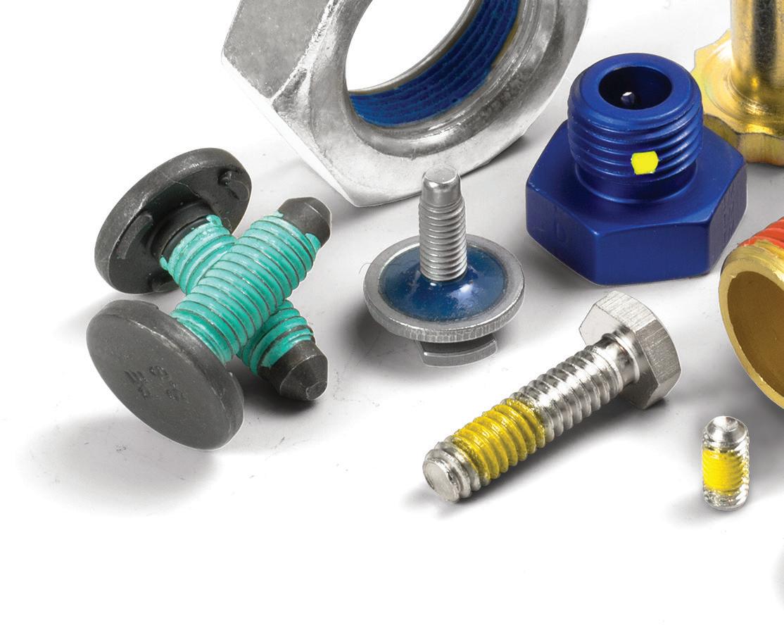
ND Industries, Inc. www.ndindustries.com info@ndindustries.com
Assemble Faster with SLIC Pins
The SLIC Pin from Pivot Point features a strong, springloaded plunger that acts as an automatic cotter. Upon insertion, the plunger automatically ramps down to pass through the application, springing back up to lock the pin in place. More consistent and easier to install, SLIC Pins eliminate the wasted motion to install a cotter, clip or nut. With separate pin/clip systems, clips can be mis-installed, forgotten altogether, or fall o later. The one-piece design of a SLIC Pin eliminates those risks, reducing product failures in the field and leading to a more consistent product. Manufactured on automated equipment, SLIC Pins are a ordable, making them an ideal solution for optimizing high-volume assembly.
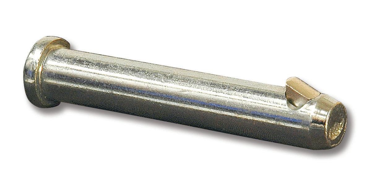
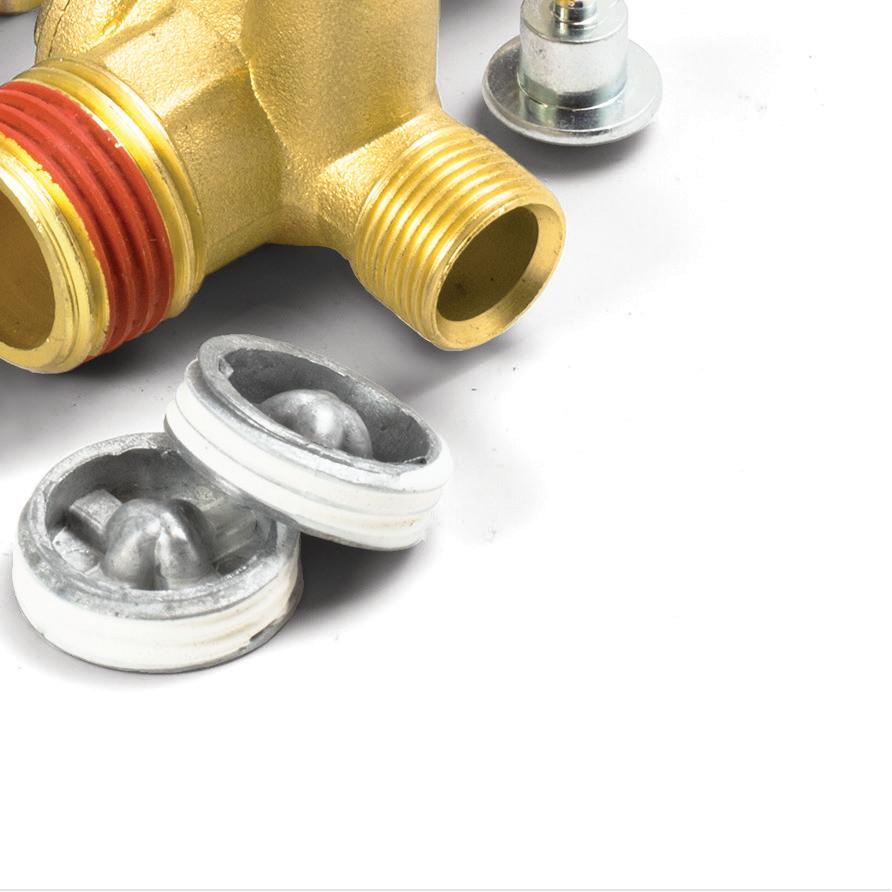
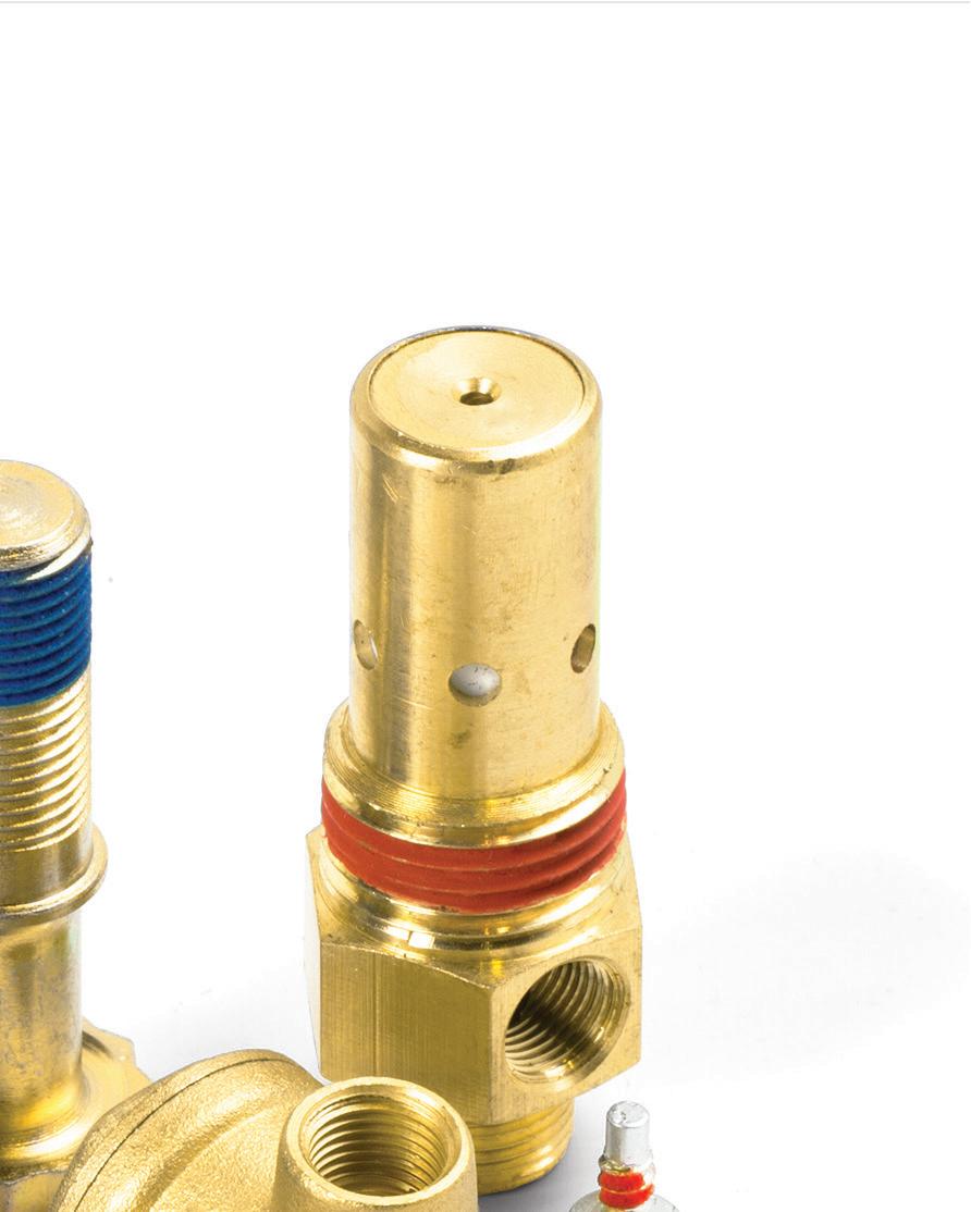
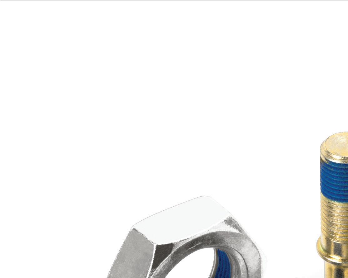
Tens of millions of SLIC Pins are installed each year, touching every industry and saving countless hours.
Explore SLIC in your application today.
Pivot Point, Inc.
Tel +1 800 222-2231 Email: mail@pivotpins.com www.pivotpins.com/SLIC

70 December 2022 www.fastenerengineering.com DESIGN WORLD
Pin and Cotter All-In-One Eliminates Cotters, Clips, Nuts Speeds Assembly Time No Tools Needed Safer Retention, More Secure As Strong as Corresponding Cotters


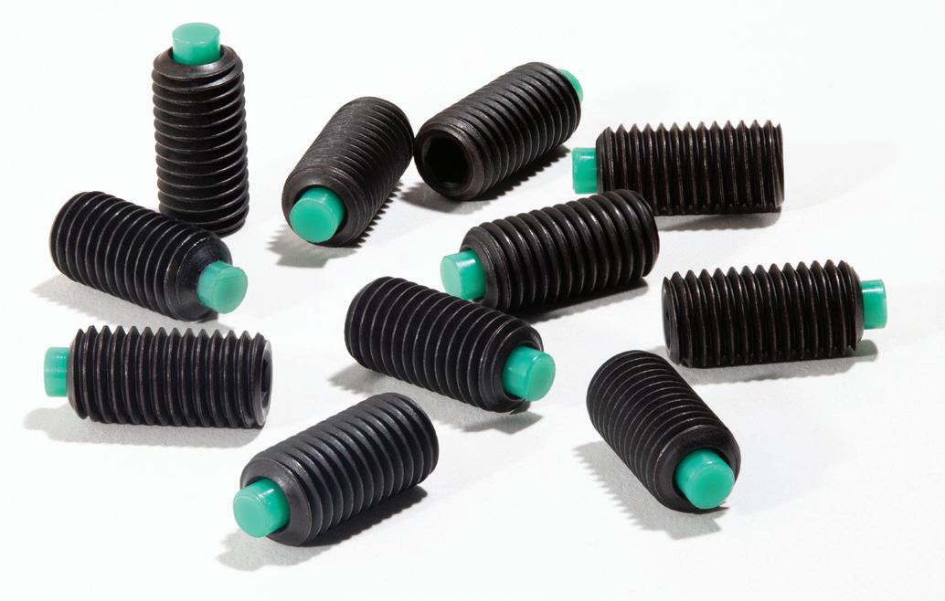

DESIGN WORLD www.fastenerengineering.com December 2022 71 Fastener Engineering A supplement of Design World September 2019 covering nuts, bolts, rivets, screws, u-clips, eye bolts, washers and more. Engineering This area has long been one of the most read and sought after by our engineering audience! From screws to bolts and adhesives to springs, these critical but often overlooked components are the key to every successful design. FastenerEngineering.com will serve readers in the mechanical design engineering space, providing news, product developments, application stories, technical how-to articles, and analysis of engineering trends. This site will focus on key issues facing the engineering markets around fastener technology, along with technical background on selected components. ADDITIONAL RESOURCES: • Special print section in select issues of Design World • Fastener Engineering monthly newsletter LEARN MORE AT: FASTENERENGINEERING.COM Setko Fasteners & Distribution 300 N. Klick St. Unit A • Hampshire, IL 60140 Sales@SetkoFasteners.com setkofasteners.com (630) 800-6377 SET SCREWS • HEX KEYS • SHOULDER BOLTS • NYLON TIP • SOCKET CAP SCREWS • STAINLESS • METRIC / INCH • ZINC PLATED SOCKETS • SHORT ARM HEX KEYS • 6-LOBE SOCKETS • BUTTON HEAD CAP SCREW • DOWEL PINS • IMPORT / USA • BRASS TIP • STANDARDS / SEMI-STANDARDS • SQUARE HEAD SET SCREWS • HEX JAM SCREWS • LONG ARM HEX KEYS • NYLON PATCH • LOW HEADS 6-LOBE (TORX) KEYS • BUTTON FLANGE CAP SCREWS Please visit us at www.SetkoFasteners.com
SALES


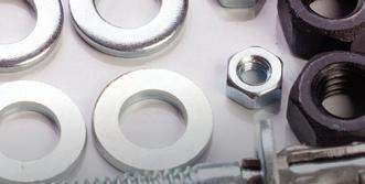
Ryan Ashdown rashdown@wtwhmedia.com 216.316.6691

Jami Brownlee jbrownlee@wtwhmedia.com 224.760.1055
Mary Ann Cooke mcooke@wtwhmedia.com 781.710.4659


Jim Dempsey jdempsey@wtwhmedia.com 216.387.1916


Mike Francesconi mfrancesconi@wtwhmedia.com 630.488.9029


Jim Powers jpowers@wtwhmedia.com 312.925.7793 @jpowers_media

Courtney Nagle cseel@wtwhmedia.com 440.523.1685 @wtwh_CSeel
LEADERSHIP TEAM
Publisher


Mike Emich
memich@wtwhmedia.com 508.446.1823


@wtwh_memich


Managing Director


Scott McCafferty


smccafferty@wtwhmedia.com 310.279.3844
@SMMcCafferty

EVP


Marshall Matheson mmatheson@wtwhmedia.com 805.895.3609
@mmatheson
72 December 2022 www.fastenerengineering.com DESIGN WORLD
Check out the digital edition! So much happens between issues that even another issue would not be enough to keep up. That’s why it makes sense to visit fastenerengineering.com and stay on Twitter, Facebook and Linkedin. It’s updated regularly with relevant technical information and other significant news for the design engineering community. fastenerengineering.com December 2022 www.fastenerengineering.com 2022 Handbook Fastener COVER_FE HBK 12-22_FINAL2.indd 1 11/22/22 1:37 PM Able Electropolishing ......................... IBC Boker’s, Inc. ............................................... 19 Emerson Industrial Automation ....... 38 J.W. Winco, Inc. ....................................... 57 Ming Tai Industrial Co., Ltd. ................. 9 NBK America LLC ................................... 29 ND Industries .................................... 24,25 Pivot Point Inc. ........................................ 15 Rotor Clip ................................................. IFC Setko Fasteners ..................................... 21 Smalley Steel Ring ............................... BC
AD INDEX Emerson Industrial Automation ....... 66 Smalley Steel Ring ................................. 67 Vendors in the fastener industry


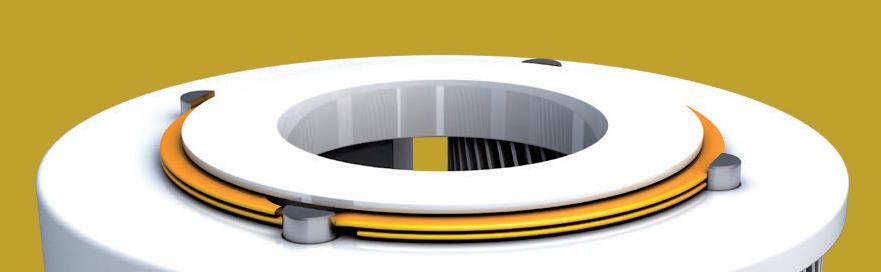
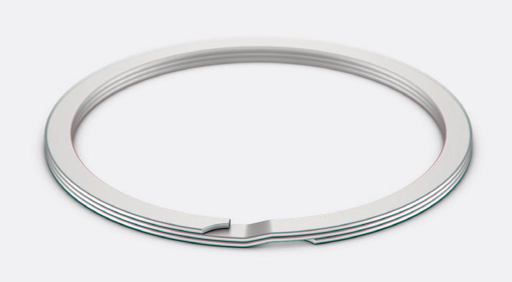
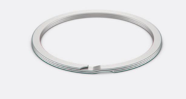
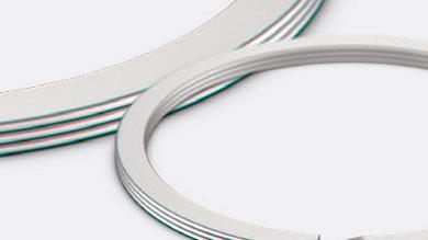
We were too. That’s why we are the only manufacturer of Spirolox®. • Easy and Quick Install/Removal • Interchangeable with Snap Rings • Large Selection from Stock • Easy to Customize SNAPSICKRINGS? OF Request Free Samples at 847-719-5900 or smalley.com Spiral Retaining Rings


