SUSTAINABLE VENTILATION
Good indoor climate with textile based ventilation
SUSTAINABLE VENTILATION
Good indoor climate with textile based ventilation
All information in this catalogue belongs to KE Fibertec AS. It may not be copied or used for any other purpose without the written consent of KE Fibertec AS.
Published by: KE Fibertec AS DK-6600 Vejen - Denmark www.ke-fibertec.com
About KE Fibertec.
KE Fibertec AS develops, manufactures, and markets “Good indoor climate” or air distribution systems based on fibre technology and sustainability.

We supply good indoor climate.
KE Fibertec AS develops, manufactures, and markets ”Good indoor climate” or air distribution systems based on fibre technology and sustainability. The foundation of KE Fibertec goes back to 1963 when Keld Ellentoft (KE) began manufacturing filterbags for industry.
Expertise and development.
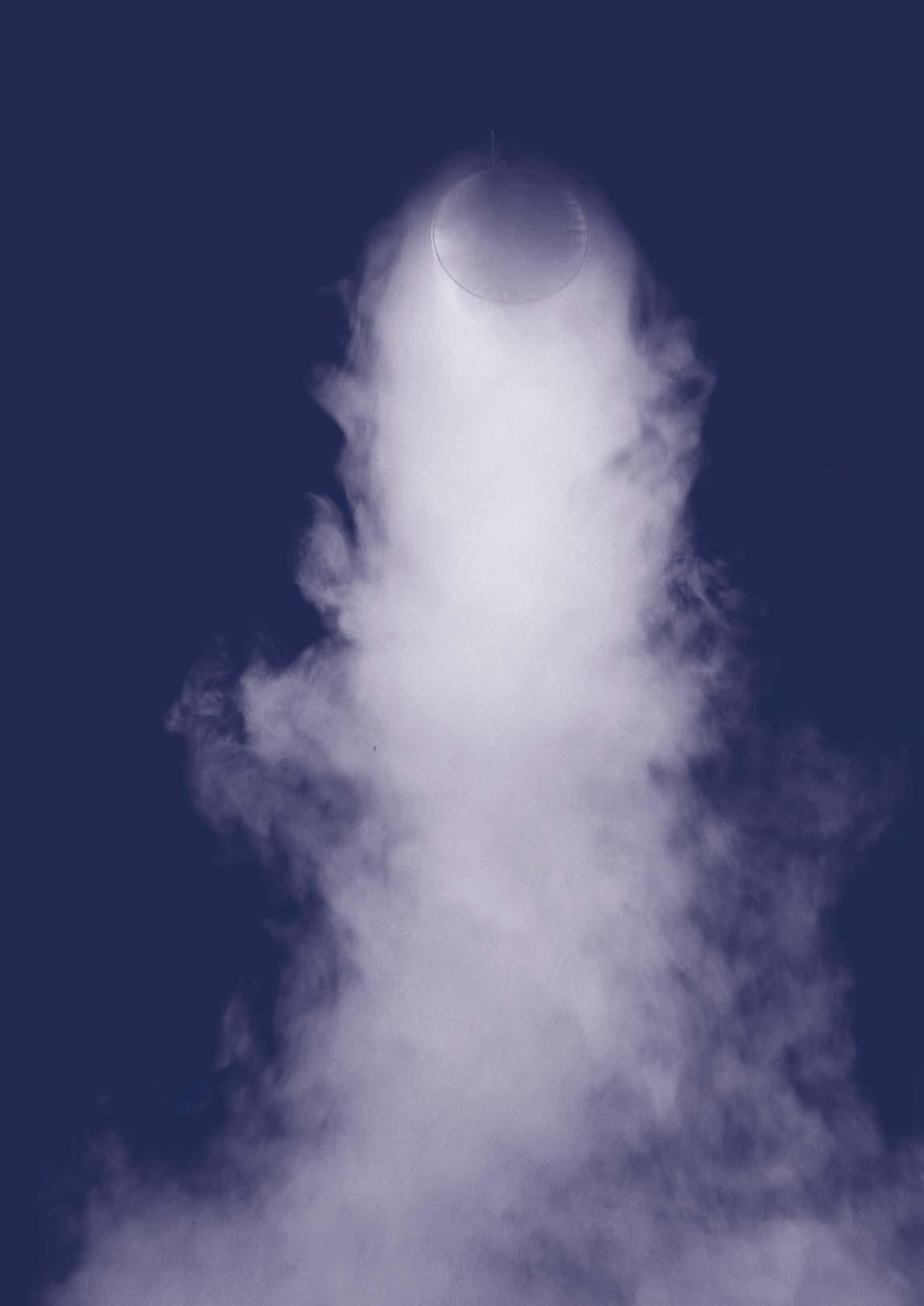
Much has changed since the first TBV system was delivered to a Danish slaughterhouse in the early 1970s. Today we have our own fully equipped fullscale laboratory enabling us to visualise solutions using smoke and to perform tests. It is also possible for us to build a full-scale model of a specific room in order to simulate various load situations. Whatever the scope of the project, our experienced and dedicated R&D staff is ready to document the solution. This also applies for on-site measurements for the end user.
Sustainability and environment.
Respect for the environment is common sense - and good business. At KE Fibertec we care about the environment and about energy. We want to make as little harm to the environment as possible both in production and in transportation of our productsand at the same time we have launched a number of in-house energy-saving initiatives to limit our carbon emission.
To minimise resource requirements and monitor our initiatives the KE Fibertec group carries out an environmental mapping process every third year. With this documentation we are able to determine if our environmental objectives have been reached and define new and ambitious objectives.
To sell “Good indoor climate” is more than just selling air distribution products. To us it is about dialogue, competence, reliability and logistics. Our philosophy is to begin with the requirements and - through dialogue - design a solution that meets the expectations specified for a good indoor climate. Just as people are different, indoor climate requirements are different, too.
It is our objective to make “Air the way you want”:
• Through advanced use of fibre technology and competent advising we wish to give our customers the benefits of textile based air distribution (heating, ventilation and cooling) in all types of buildings.
• We will continue to strengthen and develop our core competences in R&D, logistics and production of textile based ventilation products in order to be the supplier of choice on selected markets worldwide.
We Care.
KE Fibertec AS practices Corporate Social Responsibility (CSR) throughout the corporation. We believe that we as a responsible company must show social responsibility by actively involving ourselves in the community and voluntarily contribute to making the world a better place to be.
UN Global Compact.
KE Fibertec respects the UN Global Compact principles which among other things involve human rights, environment, and anti-corruption. Read more about how we work with the principles at www.ke-fibertec.com.
Working environment.
Our employees are KE Fibertec’s greatest asset, and therefore we prioritise their well-being in relation to their safety, health, and environment. The company is certified according to the ISO 45001:2018 Standard that ensures a good working environment. Further, we focus on the personal and professional development of every single employee to ensure that all members of our staff find it challenging and satisfactory to go to work.
Charity.
For many years KE Fibertec has sponsored children’s and handicap organisations as well as other organisations where we believe that we can make a difference. Our partners around the world also join our efforts.
Healthy indoor climate.
Our goal is to create healthy indoor climate“Air the way you want” - by developing and manufacturing air distribution systems based on fibre technology and sustainability.
KE Fibertec is your worldwide supplier.
Today the KE Fibertec Group is represented all over the world and employs more than 120 people, the majority working in our four sales subsidiaries in the UK, Germany and the USA as well as Euro Air A/S. Furthermore, the group runs two production companies, KE Fibertec Væveri (weaving mill) and Euro Air CZ.
With the acquisition of our competitor, Euro Air A/S and Euro Air CZ in September 2007, the KE Group has consolidated its position as the world’s largest manufacturer of textile ducting.
World’s first Cradle to Cradle-certified ventilation duct.
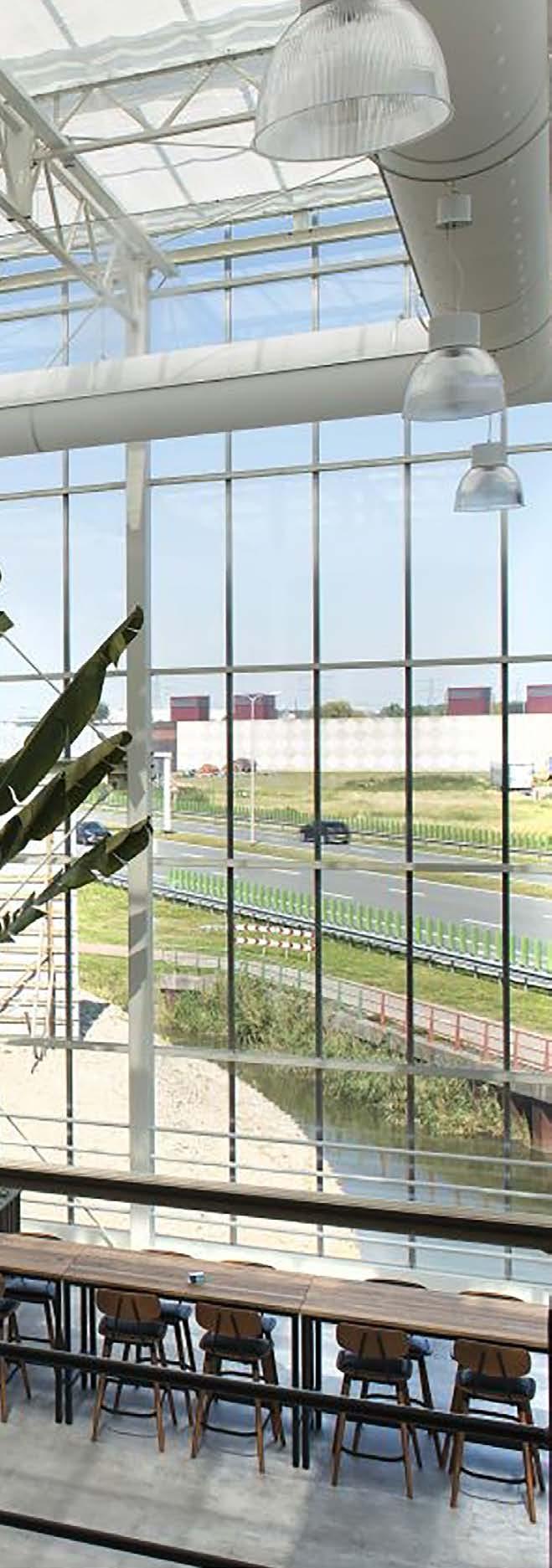
CradleVent® is the world’s first ventilation duct to be approved as a Cradle to Cradle certified product by the prestigious EPEA Institute in Hamburg, Germany. CradleVent® is our idea of a long-term and sustainable product for air distribution in offices, schools, laboratories, sports halls, public buildings, and other comfort environments.
The increasing demands of contractors and architects on sustainability and resource efficiency make it attractive to include CradleVent® as a welldocumented component of construction.
Own weawing mill.
KE Fibertec is the only manufacturer of textile ducts worldwide to have their own weaving mill, KE Fibertec Væveri AS. The weaving mill was established in 1972 and is today run by Mr Frank Hansen who is director and third generation of the family business.
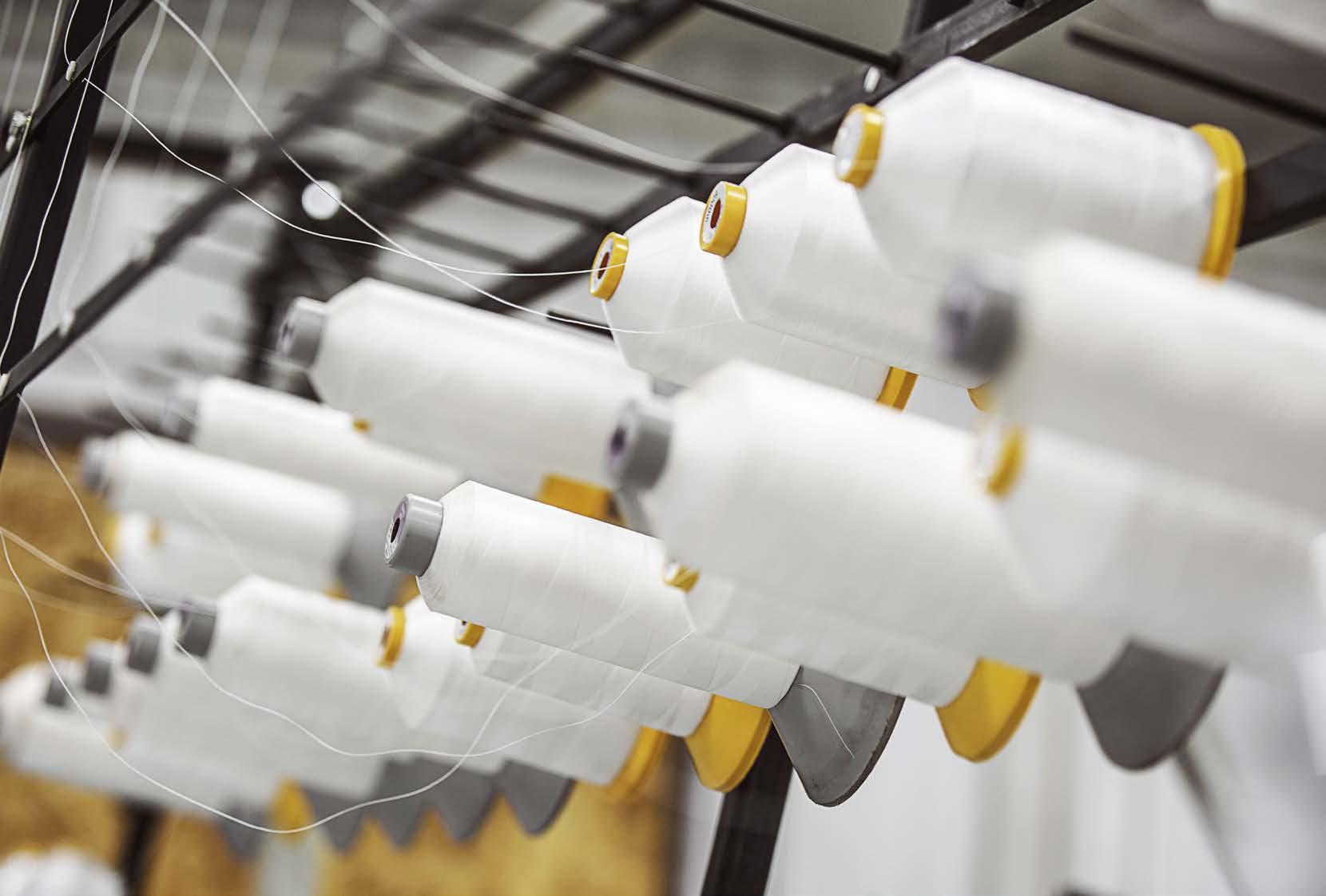
The weaving mill exclusively manufactures fabrics for textile duct ventilation which is a unique situation on the global market and which gives us a valuable know-how on these materials for the benefit of our customers. To have our own weaving mill just across the parking lot gives us a very flexible cooperation partner who can meet our demands and requests on especially quality control and supply security.room in order to simulate various load situations.
Whatever the scope of the project, our experienced and dedicated R&D staff is ready to document the solution. This also applies for on-site measurements for the end user.
KE Fibertec Væveri has very strict demands on suppliers of yarn, and all raw materials are subject to extensive input control to ensure that the permeability is unchanged even after many washes. A barcode enables us to monitor the fabric which gives us full traceability in relation to production date, permeability, etc. - from reel to finished product delivered and installed at the end user.
Further, the weaving mill supplies special materials such as Nomex, GreenWeave, MultiWeave and Antistatic GreenWeave materials.
KE Fibertec Væveri manufactures a large number of different permeabilities in many different yarn-dyed colours, in total almost 100 different product items. Most of the materials are Cradle to Cradle certified.
Own laundry facilities.
All ventilation ducts must be maintained at some point, regardless of whether they are low impulse systems where the air diffuses through the surface and the dust is retained on the inside or high impulse systems where induction dust settles on the surface and around the supply openings. The advantage of a textile duct is that it can be easily removed and washed.
Advantages of maintenance.
A properly maintained textile based ventilation system ensures 20-25 years of trouble-free operation with a number of advantages:
• Lower energy consumption due to correct pressure loss and less clogging in the TBV duct. KE Fibertec offers impact calculations of optimal washing interval.
• Healthier indoor climate, as the particulate matter and other airborne particles are retained and washed out during the washing process.
• Longer service life and as an extra benefit, the product warranty can be extended up to 15 years with an official KE Fibertec washing agreement.
Environmental washing process.
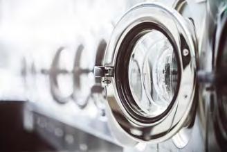
KE Fibertec offers a comprehensive maintenance program with own in-house laundries in most major markets. All washing programs have been developed in collaboration with leading suppliers and they ensure a gentle and environmentally correct washing process.
In addition, KE Fibertec offers a certified Antibacterial treatment without harmful silver ions.
Washing Service.
Why textile based ventilation?
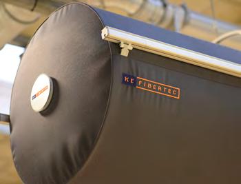
In principle a textile duct is a round, semi-round or quarter round duct made of a light-weight textile material instead of e.g galvanized steel, stainless steel or aluminium, designed for delivery and distribution of cooled or heated air.
Good indoor climate.
Textile ducts are very well-suited for efficient, uniform, and draught-free distribution of fresh air without ”dead zones”. Stale and stagnant air may cause fatigue and headache. KE Fibertec’s textile ducts create an efficient air change and a good indoor climate in schools, offices, shops, showrooms, and other types of rooms where many people are assembled.
Flexibility and tailored solutions. Flexibility and tailored designs characterise KE Fibertec’s textile based ventilation (TBV) solutions. Here you may freely choose the size that fits the architecture of the building the best. Also, you may choose from an almost unlimited range of system layouts, colours, materials, and whether the TBV system must be passive, hybrid, or active.
Unique materials and colours.
As the only manufacturer in the world we offer customised woven textiles from our own weaving mill. Our materials are designed for air distribution - not for tents or patio blinds when it comes to uniform air distribution, shrinkage after washing, colour-fastness, and not least best possible Dust Holding Capacity.
Advantages of textile ducts
• Efficient air distribution and good indoor climate
• Flexibility and customised solutions
• Unique materials and colours
• Fire tested and approved materials
•
•
•
•
•
We offer a wide range of standard colours and in addition to that our textiles may be dyed in any desired colour according to a standard colour system (at extra cost).
Easy to transport and install.
Our materials weigh 260-330 g/m² which is much lighter than metal spiral ducts. Additionally, textile ducts are much easier to handle and transport as they are folded and packed in cartons of a maximum weight of 25 kg.
KE Fibertec’s suspension rails are delivered in exact lengths rendering installation easier and quicker than for similar systems.
Textile ducts made of Polypropylene
1978 1989 ABOUT KE FIBERTEC / THE TIMELINE
KE Fibertec develops and patents KE-Inject® LV system - first TBV system for heating 1993
KE Fibertec buys own weaving mill, KE Fibertec Væveri AS

Introduction of WinVent, KE Fibertec’s 3D design software
1998
Textile ducts made of 100% polyester
KE Fibertec develops the DireJet® nozzle for directional air distribution
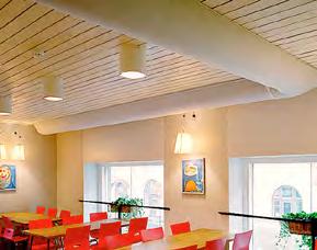
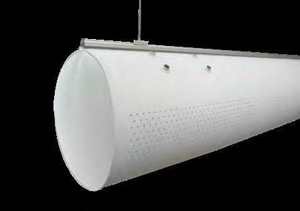
Textile ducts made of Trevira CS® Polyester
1999 2000
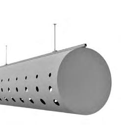
KE Fibertec introduces textile ducts with laser-cut holes

The history of TBV.
Initially, TBV meant a simple duct designed for slaughterhouses for the delivery and distribution of very high quantities of cold air into the occupied zone with minimal draught in order to improve working conditions. Back in the early 70’s the appearance of ducts was not an issue - only the function. At first it was just a simple “bag” made of cotton attached to the end of a cooler or grille that would inflate and slowly let the air out. Over the years, the ways of distributing the air in a room have changed - from simple material diffusion to applying nozzles and holes to distribute warm and cold air. This was a natural development since the segment today not only applies to cold rooms but also to high demand comfort rooms such as offices and schools.
1974 10
2012
Sustainability with CradleVent® textile ducts
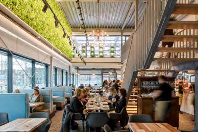
KE Fibertec introduces next generation dimensioning software, TBV Designer
2017
New material concept introduced. GreenWeave, MultiWeave and ZeroWeave
New Inject Flex product. A family of multiple-sized laser cut holes. From Ø4 mm to Ø70 mm
2020
2019
KE Fibertec develops the intelligent textile duct InTex®
KE Fibertec develops the Vario nozzle

BIM objects for textile duct dimensioning in Revit now available
KE first company in DK to be recertified acc. to the new ISO 9001:2015 and ISO 14001:2015 standard
In-house textile duct laundry
The core product.
KE Fibertec AS develops, manufactures, and markets “Good indoor climate” or air distribution systems based on fibre technology and sustainability.
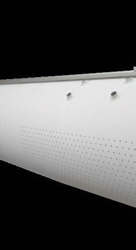
To sell “Good indoor climate” is more than just selling air distribution products. To us it is about dialogue, competence, reliability and logistics.
Our philosophy is to start with the requirements and - through dialogue - design a solution that meets the expectations specified for a good indoor climate. Just as people are different, indoor climate requirements are different, too.
It is our objective to make “Air the way you want”
Green Thinking.
We want to be innovative and creative - we strive to set the standards in textile based ventilation products worldwide in functionality and in our choice of sustainable materials. At KE Fibertec we care about the environment and about energy. We want to make as little harm to the environment as possible both in production and in transportation of our products.
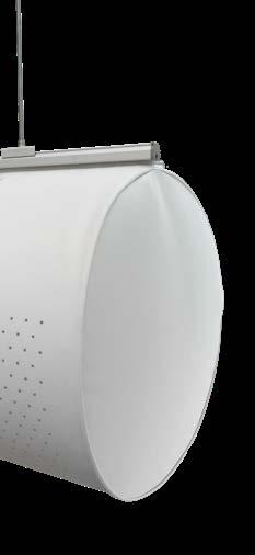
Know-how.
We want to supply the best quality in the market and on time. We do not compromise with quality, neither regarding design, documentation, nor finished products. Our goal is to be a professional partner with high demands on our performance, but also with high expections and demands on our suppliers and cooperation partners.
Product Lifetime Extension.
We want to ensure our customers a long lasting solution both in clean air and with energy savings. A clean textile duct provides healthy indoor climate and energy savings that will benefit not only the environment but also the operating economy of the plant. With a complete programme of service and maintenance we offer solutions with an extended lifetime to our customers.
Green Thinking.
KE Fibertec has a focus on sustainability and how we can contribute to a lower environmental impact - we call it “Green Thinking”.
Our CradleVent® ventilation duct is based on the Cradle to Cradle concept that documents the sustainability of the product from Cradle to Cradle, ie. from product to recycling.

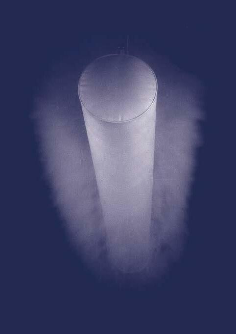

Green Thinking.
Sustainable thoughts and responsibility are here to stay. Global environmental problems, more stringent energy requirements in the building industry, and the lack of resources such as coal and oil demand that we bring words into action and start taking an interest in more sustainable and future-proof alternatives. Cradle to Cradle fits perfectly into that equation since you do not use new materials, but recycle materials wherever possible.
For many years, KE Fibertec has worked purposefully and intensively with sustainability with a focus on how we, as a global production company, can help to make a difference and have the least possible impact on the environment. Today, the whole circular mindset is a big part of our DNA and the way we develop our products and optimise all processes. By choosing textile ducts you are doing something good for the environment:
• Because of the low weight of textile ducts the fuel consumption during transport (and therefore the carbon emission) will decrease remarkably compared to transporation of traditional steel ducts.
• A properly dimensioned textile duct system is able to operate optimally at a lower pressure drop than conventional ceiling diffusers.
• The air distribution with textile ducts is better, and it is therefore possbile to offer a solution that does not take in ”unnecessary” air. This results in energy efficiency - and a better indoor environment.
By choosing KE Fibertec textile ducts, you are doing something good for the environment.
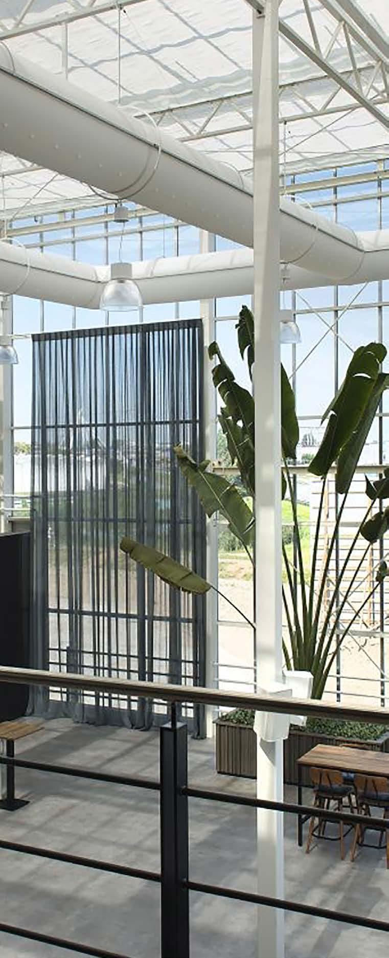
Materials.
Ss the only one producer in the world all textile materials come from our own weaving mill. Our materials are exclusively produced for textile based ventilation purposes. We primarily apply yarn-dyeing and Cradle to Cradle yarns and thereby we save the environment from many litres of waste water annually and overall it results in a much smaller carbon footprint compared to conventional materials.
Building certification.
With our Cradle to Cradle product certification, we support a number of international building certifications such as LEED version 4, BREEAM, NL with points for material ingredients. In addition, textile ducts contribute to reduced fuel consumption during transport and handling due to the low weight compared to traditional steel ducts.
Recycling.
KE Fibertec is continuously working to increase the recycling rate in all products. All aluminum included in the mounting rails and all bulb cords are made with a high degree of recycling. On all C2C products we offer a “buy-back programme” when the textile ducts are no longer functional.
Carbon reduction.
At our Danish factories we have for more than 10 years worked intensively to reduce our carbon footprint and have reduced the impact by 52% per turnover DKK since 2010. All electric power consumed is generated by wind turbines and thereby carbon neutral. KE Fibertec works with an ambitious goal of becoming carbon neutral by 2030. On top of that KE Fibertec is certified according to ISO 14001:2015 (Environmental standard).
UN Global Goals (SDGs).


Based on the Cradle to Cradle standard, which supports 11 global goals, it is a natural development for KE Fibertec to work towards a Global Goal certification. For more information follow the further development at www.ke-fibertec.com/globalgoals.
Environmental Mapping.
KE Fibertec publishes an annual CSR report which can be downloaded at www.ke-fibertec.com.

Cradle to Cradle.
Since KE Fibertec obtained a Cradle to Cradle certification in 2012 by the EPEA institute in Hamburg a lot has happened. At the beginning it was only a white CradleVent duct, but today we can offer a large part of our material range in a number of colours (dope-dyed yarns) approved according to the sustanability standard.
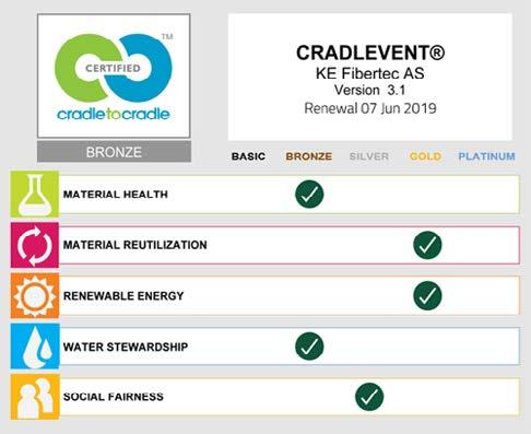
The Cradle to Cradle standard consists of five fundamental building stones (see below) and it is much more than just recycling a percentage of bottles or other waste materials in one cycle (cradle to grave). In the Cradle to Cradle concept you see waste as food for a new production, which creates balance in the cycle.
The definition and description of the Cradle to Cradle standard is:
Material Health

Inventorying material chemistries as low as 100 ppm and assessment in relation to chemical risks and exposure.
Material Reutilization
Assessment of recycled or rapidly renewable materials. Which parts of the product can be recycled or repurposed (technical circuit).
Goal
The goal is that KE Fibertec’s products only consist of materials and substances that are 99.99% harmless to humans.
Goal

The goal is to reach as high a recycling rate as is technically possible. The recycling rate on our products is 18-25% in 2021 figures. KE Fibertec offers a repurchase agreement on all CradleVent orders.
Renewable Energy
Survey of energy consumption and the share of renewable energy used for manufacturing the product.
Water Stewardship

Survey of water consumption and waste water quality. The aim is to ensure clean water for future generations.

Social Fairness
Does the company act in accordance with recognised standards of social responsibility? The aim is to ensure fair working conditions for the employees at all levels of the supply chain.
Goal
KE Fibertec currently uses 100% wind power, and we are working on a conversion from gas to a carbon neutral energy source for heating. KE Fibertec’s goal is to be carbon neutral by 2030.
Goal
All waste water is collected and treated at a treatment plant. Yarn dyeing is used instead of piece dyeing, which gives a saving on waste water of approx. 67%.
Goal
All of KE Fibertec’s main suppliers have signed the ten principles of the UN Global Compact.
Sustainability in practice.
Our weaving mill, KE Fibertec Væveri uses all surplus warp yarn to produce bulb cords which are used for suspending the textile ducts in the mounting rails.
The surplus yarn is wound onto larger spools and recycled 100%. Therefore, there is typically a colour difference in the core of the bulb cords, but they are always covered by a material cover in the colour of the textile duct.
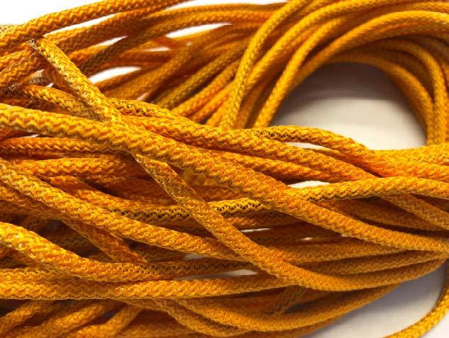
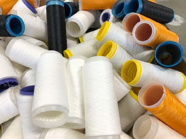
The advantage of this solution is that the bulb cords automatically comply with all the standards for which KE Fibertec’s materials have been tested, e.g. Cradle to Cradle, UL 2518, EN 13501 (B-s1-d0) fire certificates and in addition they are shrink-stabilised down to 0.5%.
The excess plastic cones are sent for recycling to our supplier of DireJet nozzles.

EPD

(Environmental Product Declaration).
For all projects KE Fibertec offers to calculate the environmental impact of the textile duct solution.
The values are stated as CO2 equivalents by converting all greenhouse gases (GHG emissions) so that they can be compared with other solutions.
CO2 equivalents are calculated dynamically in our TBV Designer programme and are based on the LCA (Life Cycle Assessment) analysis prepared by 2.-0 LCA consultants in Aalborg, DK.
Example:
The environmental impact for a Ø500 x 10,000 mm textile duct suspended in a Safetrack rail is 116 kg CO2 eq at a total air volume of 5,000 m3/h.
Design and Engineering.
Textile ducts are very well-suited for efficient and uniform distribution of fresh air without draughts or “dead zones”.
KE Fibertec makes tailored solutions to provide efficient and healthy indoor climate in all types of buildings.

Where our products are used.
Textile ducting can be used in almost any type of installation and building, irrespective of whether the requirement is for heating, cooling, ventilation or a replacement air system. Over the years, KE Fibertec and our partners have accumulated a large database of references covering every possible installation and we can safely guarantee that we have a solution to suit your inquiry. You will find a number of references at ke-fibertec.com.


Why choose textile based ventilation?
Flexibility and tailored products are the hallmark of our TBV solutions. This allows you to freely choose the size that best suits your design rather than having to be tied to a particular number of standard solutions.

In addition to this, the options offered when it comes to selecting system layouts, colours, offsets, elbows, sockets and materials are endless, not to mention that you can choose whether the TBV system will be passive (low impulse), semi-active (hybrid) or active (high impulse). In a nutshell, there could not be more options available for achieving optimum air distribution.
Unique materials
Our textiles are produced at our own weaving mill with the sole purpose of offering the most suitable materials for air distribution in the market. The selection of fibres, weight, weaving technology, dyed yarns and heat treatment are based on our desire to achieve totally uniform air permeability, a large dust holding capacity, the lowest possible shrinkage after washing and basic colours without any additional cost.
Efficient air distribution and good indoor climate
Textile ducts are very well-suited for efficient, uniform, and draught-free distribution of fresh air without ”dead zones”. Stale and stagnant air may cause fatigue and headache. KE Fibertec’s textile ducts create an effective air change and a good indoor climate in schools, offices, shops, showrooms, and other types of rooms where many people are assembled.
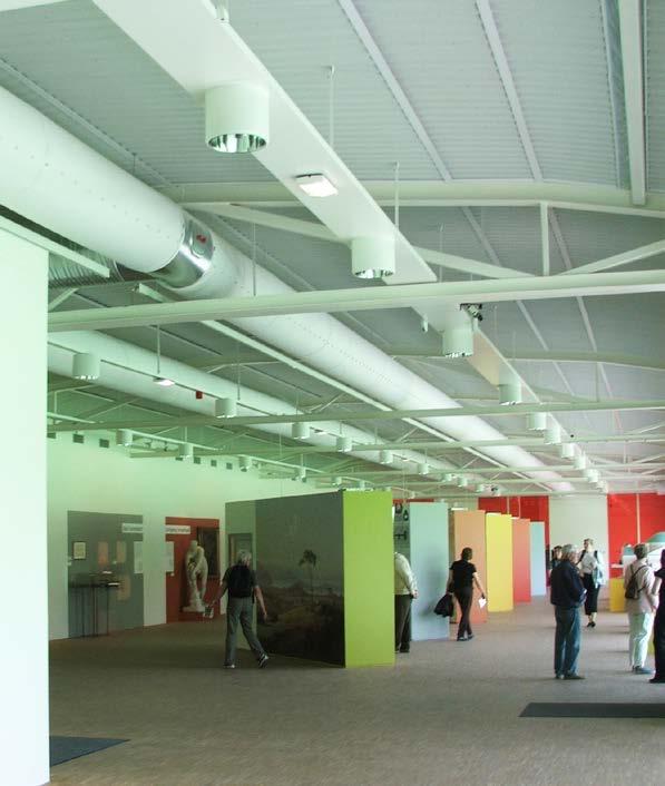
Easy to transport and install
Our materials weigh 260-330 g/m2 which is much lighter than metal spiral ducts. Addiitionally, textile ducts are much easier to handle and transport as they are folded and packed in cartons of a maximum weight of 25 kg. KE Fibertec’s suspension rails are delivered in exact lengths rendering installation easier and quicker than for similar systems.
Hygienic and easy to maintain
All TBV systems can easily be taken down and washed in a washing machine. The specially treated polyester materials absorb no more than 1% of water, even with a relative humidity of over 90%. This is why they are approved for the food industry. In extremely humid environments you may choose an antibacterial treatment that renders the textile ducts resistant to mould and microorganisms.
Sustainable ventilation
KE Fibertec offer a full sustainable ventilation solution, either certified according to the Cradle to Cradle standard with 100% recyclability and a disposal take-back-warranty, or sustainable Cradle to Cradle or OekoTex certified yarns. Our production is certified to ISO 14001:2015 standard (Environment). Transportation and disposal of textile duct systems produce less carbon pollutants than conventional steel ducts.
Guide to selecting the best TBV system.
In the following section we have created a product chart based on type of application matched with the best product choice. The approach taken when the charts were built was how to generate “added value
Application:
or the best possible value for money”. However, other products can also be used for a particular installation if the assessment is based on other requirements.
Recommended system: Ventilation type:
KE-Low Impulse System
KE-Interior System
CradleVent®
FBS Panels
Comfort
Low impulse ventilation / Displacement ventilation
Hybrid ventilation
KE-Inject Hybrid System
KE-DireJet System
CradleVent®
KE-Low Impulse System
KE-Interior System
CradleVent®
Mixing ventilation Hybrid ventilation Laboratories

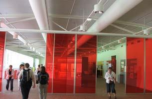
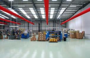
Industry
FBS Panels
KE-Inject Hybrid System
KE-DireJet System
CradleVent®
KE-Low Impulse System
KE-DireJet System
KE-Inject Hybrid System
KE-Interior System
KE-DireJet System
KE-Low Impulse System
Mixing ventilation
Low impulse ventilation / Displacement ventilation Hybrid ventilation Sports
Low impulse ventilation / Displacement ventilation Hybrid ventilation
Mixing ventilation
Low impulse ventilation / Displacement ventilation
Hybrid ventilation
Mixing ventilation
KE
KE
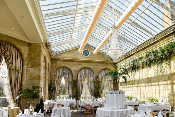

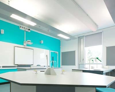
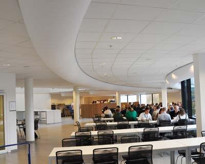
 Walkden High School, UK
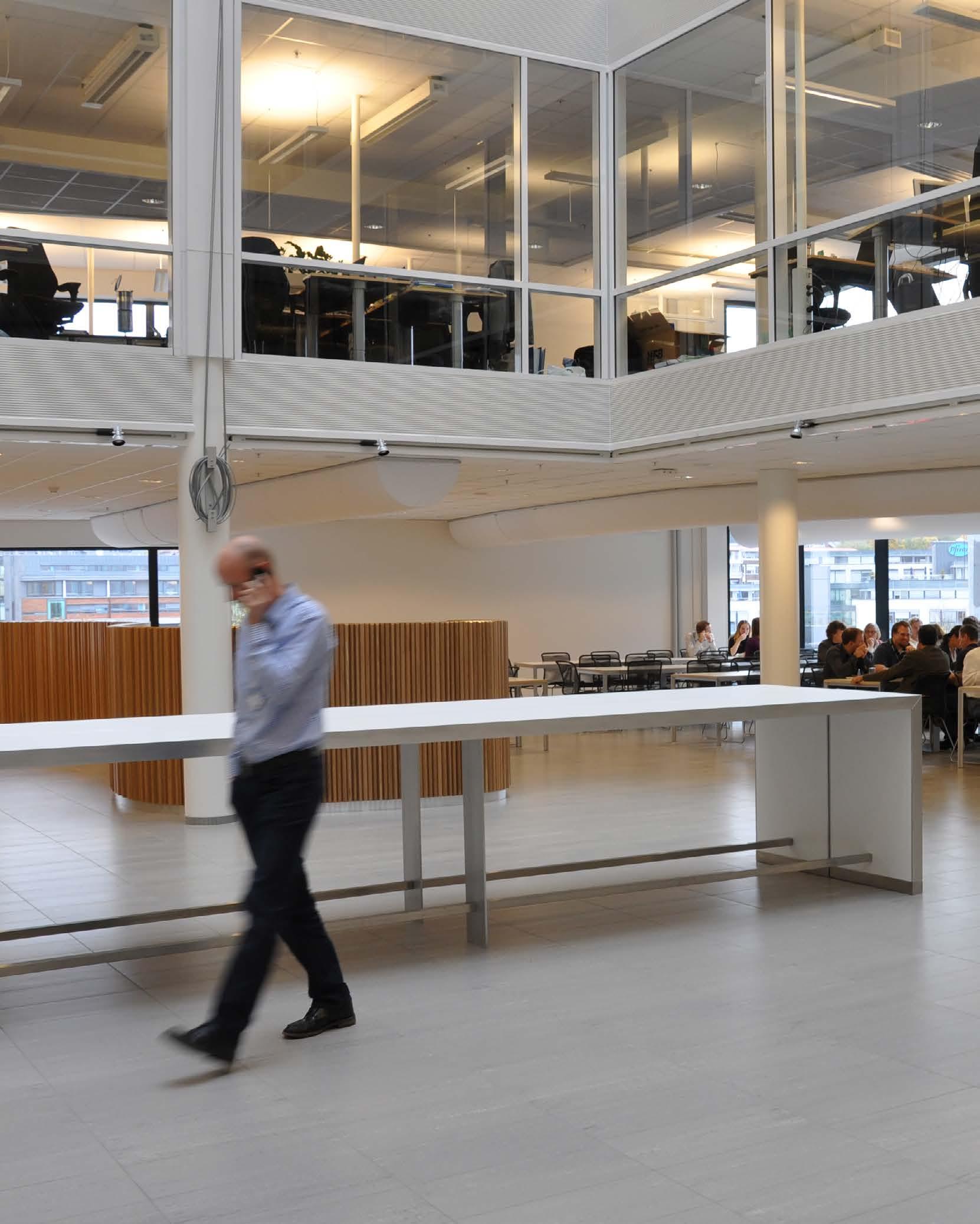
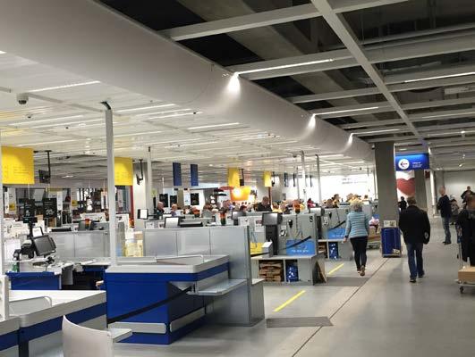
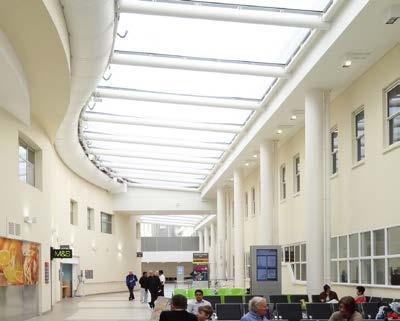
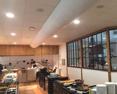
Lysaker Torg, Norway
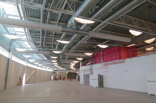
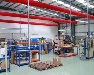
KE References for Industrial Ventilation
Production premises, Storage rooms, Printing works, Vehicle workshops

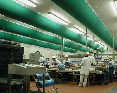
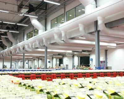
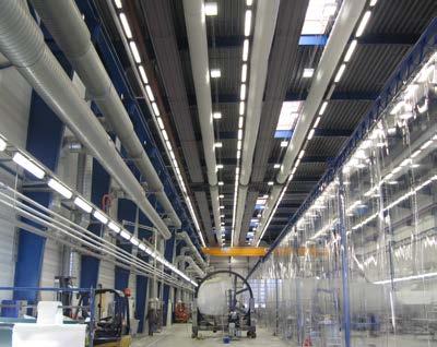
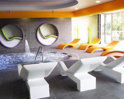
KE References for Industrial Cooling Equalising rooms, Slicing rooms, Warehouses, Food terminals
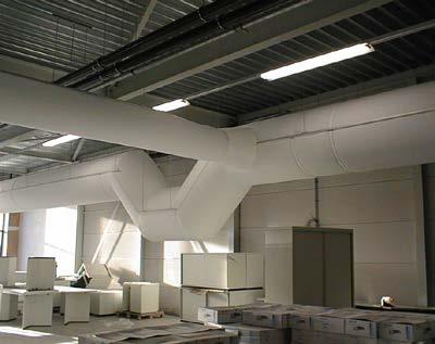
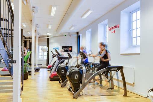
KE References for Sport and Leisure Swimming pools, Sports arenas, Fitness studios
To explore more of our references, visit www.ke-fibertec.com
 Danish Crown, Holsted, Denmark Arla Foods, Sweden
Plantijn Casparie, Holland LM Wind Power, Denmark
Ocean Spa Essex, UK
Basildon Sporting Village, UK
Friskis & Svettis, Sweden
Lohmann Tapes, UK
Products.
Flexibility and tailored designs characterise KE Fibertec’s textile based ventilation (TBV) solutions. Here you may freely choose the size that fits the architecture of the building the best.
Also you may choose from an almost unlimited range of system layouts, colours, materials, and whether the TBV system must be passive, hybrid, or active.

Main products.
KE Fibertec develops and markets three main TBV product groups, which can all be supplied in three different geometries. In passive low impulse systems the air diffuses through a permeable material. In high impulse systems air is distributed solely through holes (KE-Inject System) or nozzles (KE-DireJet System). The hybrid models are a combination of the passive low impulse systems and the lasered Inject holes or DireJet nozzles.


Product range: Low impulse systems


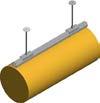
KE-Low Impulse System
Textile based ventilation systems. The air distribution principle used for a textile based ventilation system is fundamentally different from a conventional ventilation system equipped with steel ducting and traditional air distribution fittings. Most architects, consultants and fitters in the ventilation industry are already familiar with the general principles of TBV systems, but not all of them are familiar with the latest product versions and design options.
KE-Interior System (½D) KE-Interior System (D)
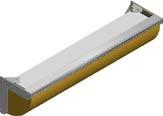

KE-Inject System

KE-Inject System (½D) KE-Inject System (D)
Product range: High impulse systems
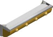
KE-DireJet System (½D)

Low impulse systems
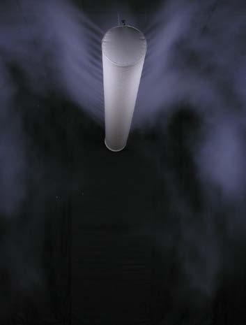
Low impulse systems.
KE Fibertec markets two products for textile based low impulse ventilation: The KE-Low Impulse System and the KE-Interior System. The KE-Low Impulse System is produced using round ducts (Ø), while the KE-Interior System is produced using half-round (D) or quarter-round (½D) ducts.


There is basically no difference in the air distribution principle when using these product versions. For this reason, just one description of the air distribution principle will be given below for the systems.
Occupied zone for low impulse systems
The occupied zone is the area in a room which people occupy for a long period of time and is defined as the area where efforts are made to maintain the indoor climate at a general level.
The occupied zone is not a standardised area, but a zone which is defined from one project to another in consultation with the architect and client. The occupied zone is often defined as the zone from the floor up to a height of 1.8 m above people who are in a standing position doing their job, while this height is set to 1.1 m for people who are seated.
Near zone for low impulse systems
In the case of horisontal low impulse systems, the near zone is defined as the zone under the textile ducting where there is the biggest risk of a “cold downdraught” or of draughts in general.
The width of the near zone can be reckoned to be no more than three times the duct diameter. In the case of vertical low impulse systems, the near zone is defined as the local zone around the duct where the air velocity is too high in relation to the room’s comfort requirements (depending on the room category).
KE-Interior System (½D) KE-Interior System (D) KE-Low Impulse SystemHorisontal low impulse systems.
The air distribution principle for horisontal low impulse systems is based on passive thermal displacement where the air is supplied at a lower temperature in relation to the air in the room.
Because of the difference in density, with the cooled air being heavier than the warmer air in the room, the room air is displaced below the duct while the supply air continues moving towards the floor. The air flow in the room is then based on natural air movements where the air is driven by the difference in density and convection flows from heat-releasing activities and processes, hence the term “passive thermal displacement”.
A high level of heat activity from heat sources generates bigger convection currents, resulting in the air rising more strongly and greater entrainment of the air around the source. This results in stratification in the ventilated room where heat and pollution are drawn away from the occupied zone and extracted under the ceiling.
Zone 1
The airflow in zone 1 is particularly reliant upon the cooling load per running metre of duct (W/m). A large cooling load leads to a more powerful acceleration of the supply air into zone 1, which results in the air dropping down and mixing with the rest of the air.
Zone 2
In zone 2 the warmer room air is displaced by the cooled air from the low impulse duct. In low impulse flows there is almost no entrainment of the surrounding room air, which can reduce the velocity level before the flow reaches the occupied zone. This means that a higher starting level will result in a higher end velocity when the air enters the occupied zone.
Zone 3
The width of the near zone is also particularly reliant upon the cooling load per running metre of ducting. The larger the cooling load, the narrower the near zone. The width at the entrance to the occupied zone can be reckoned to be no more than three times the diameter of the low impulse duct.
A low impulse system can only be used for cooling purposes or for distributing large volumes of isothermal air, as warm air will settle under the ceiling like a blanket. When this occurs, the supply air is short circuited, which means a waste of energy.
KE Fibertec’s textile based low impulse systems are woven from GreenWeave polyester yarn, and the textile surface acts as a fine mesh, allowing the supply air to pass through the surface at a very low, uniform discharge velocity, which is normally less than 0.1 m/s. If the air needs to be distributed according to the low impulse principle the discharge velocity should be maintained below roughly 0.400.50 m/s. This is the limit at which the room air will start to be entrained and mixed with the low impulse flow.
The picture below illustrates the air distribution principle for horisontal low impulse systems.
Zone 1
Zone 2
Near zone
Zone 3 1.8 m
As has just been mentioned on the previous page, the cooling load per running meter of ducting is crucial to how the air flow will be under the ducting, but the location of the heat sources in the room also has a major influence on the air flow. The following parameters are crucial for air velocity and air temperature under the duct:
Cooling load per running metre of ducting
Large cooling demands result in higher discharge velocities and a greater temperature difference between the room air and the supply air (DT). Both these parameters end up accelerating the supply air’s velocity.
Location of heat sources
Measurements have shown that equally distributed floor heat accelerates the discharge velocity much more than heat sources located high up in the premises (1.5 to 2 m above floor level).
Unlike the cooling load per running metre of ducting, the static pressure, which keeps the textile duct inflated, does not have any particular influence on the air flow’s distribution in the room. No matter how great the static pressure is in the duct, there is not sufficient force (momentum) in the jet to give the air a throw length which is typical of KE Fibertec’s high impulse systems.
As mentioned previously, it is important to clarify how the heat load is distributed in the premises as it makes a big difference whether the heat loads come from machines, people or lighting, or whether it mainly takes the form of transmission heat from surrounding premises. As low impulse flows are only controlled by thermal forces, the location of heat sources and heat-releasing processes in the room is a vitally important parameter when calculating low impulse flows.
KE Fibertec’s room classification (as also shown in datasheet 1) takes into account the heat distribution which normally occurs in different types of premises. You are recommended to use these dimensioning values. The room classification and information in datasheet 1 give clear guidelines on how large the cooling load can be with different comfort level requirements.
The static pressure, which keeps the textile duct inflated, does not have sufficient momentum to give the air a throw length which is typical of KE Fibertec’s high impulse systems. Due to the difference in density between the supply air and the room air, the supply air is displaced towards the floor immediately after passing through the textile surface.
If the premises mainly has large concentrated heat sources it is important for low impulse ducts to be placed lower in the room and distributed between the heat sources rather than above in order to achieve a good displacement effect and prevent unnecessary mixing with the polluted air from the upper zone and buoyancy from machines.
This will help to flush the work zones under the textile ducting very effectively. It is extremely important that the number of textile ducts and their location precisely match that of the machines and that the ducting runs for the whole length of the heat source.
If the heat sources are distributed more evenly, like in office premises for instance, the low impulse ducts should be placed in corridor areas or along walls to avoid a drop of cold air at fixed workplaces. If the upcoming convection heat blocks the low impulse current, undesirable stratification can occur, with cold air on top and hot air underneath.
Location of heat sources
At heat sources convection heat rises up and will, at a certain propagation angle, meet the downcoming air from the ducting. This phenomenon is also encountered with large window panels where the convection heat from radiators located under the windows counteracts the cold downdraught.
If the heat sources are located at a height the resulting air velocity will be somewhat lower when the current arrives down in the occupied zone. In other words, if the downcoming air velocity is greater than that of the upcoming warm air, the current will continue downwards, but at a reduced velocity.
In theory, you can calculate the convection velocities above almost every common heat source. If you also know the air velocity under the low impulse duct you can, in principle, calculate the resulting air velocity, but this procedure is definitely not to be recommended! In reality, you will come across countless instances where the cold current can “spread out” to the side and veer away from the duct’s centreline and continue at a greater velocity than expected, with the subsequent risk of draught problems.
To avoid a sudden drop of cold air, known as a “turbulence draught”, it is important to create a balanced system so that the risk of a drop of cold air does not arise.
The location of the exhaust grilles also affects the air distribution in the premises. Return flow towards an exhaust grille positioned at floor level can feel like a draught, especially in cold production facilities where even very low air velocities feel uncomfortable.
The usual recommendation is for extraction vents to be positioned at ceiling level, spread a certain distance apart. Large doors or windows which are opened regularly also have an impact on air distribution as the uneven pressure conditions can cause an inflow of air from outside and from surrounding premises.
The figures below illustrate the typical flow pattern under a horisontal KE-Low Impulse System in a heating scenario, ventilation scenario and two
cooling scenarios with a different cooling load per running metre of ducting.

∆T < 0°C

A delivery of heated air results in the supply air being short circuited where the air forms a blanket under the ceiling. Low impulse systems are therefore not suitable for heating.
B
D
∆T = 0°C
A delivery of isothermal air produces a very diffuse flow pattern. Downward air movements (in the direction of the occupied zone) are often required, in which case the recommendation can be made to increase the discharge velocity to 0.40-0.50 m/s, which is the limit if the air is going to be supplied according to the low impulse principle. At discharge velocities above 0.50 m/s you can expect the surrounding room air to start being entrained.
∆T < 3°C
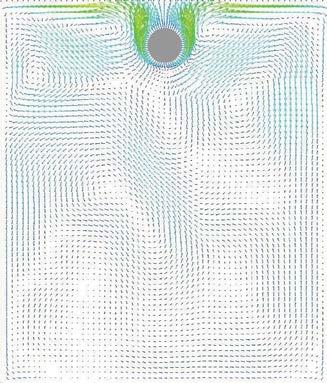
A delivery of supercooled air produces the typical downward flow pattern characteristic of low impulse ventilation using textile ducting. A delivery with a moderate cooling load does not, under normal circumstances, cause any discomfort in the near zone, even for those people who are seated. The maximum cooling load obviously depends on the distance from the low impulse ducting to the occupied zone. The maximum cooling loads per running metre of ducting as a function of the room’s height can be consulted in datasheet 1.
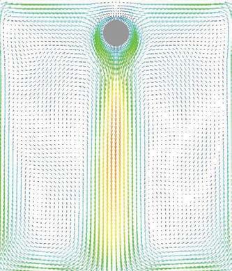
∆T > 5°C
As the cooling load per metre of ducting increases, the flow pattern under the low impulse duct changes and the near zone becomes narrower, which means that the air velocities and air temperatures vertically under the duct may cause discomfort. A delivery of extremely supercooled air with a cooling load of more than 700 W/m of ducting should mainly only be used where comfort is a minor consideration. However, it is possible to deliver very large volumes of cool air, bearing in mind though that the air distribution will not be 100% perfect.

Vertical low impulse systems.
The air distribution principle for vertical low impulse systems is, as with horizontal low impulse systems, also based on passive thermal displacement where the air is supplied at a lower temperature in relation to the room air. The air is supplied, as in conventional displacement ventilation, at floor level, directly in the occupied zone. This creates a stratified flow where the cooled supply air flows out into the room under the warmer room air.
In the same way as with horisontal low impulse systems, the flow in the room is based on natural air movements where the air is driven by a difference in density and by convection flows from heat-releasing activities and processes.
Convection flows at heat sources generate a vertical air flow in the room, thereby creating a clean zone on the bottom and a polluted zone on top. A high level of heat activity from heat sources generates bigger convection flows, resulting in the air rising more strongly and greater entrainment of the air around the source.
As the cold supply air only mixes to a small extent, it is important the air is supplied at a low velocity and slight temperature difference as otherwise there is a risk of a cold downdraught from the ducting, entailing the risk of a draught at floor level. The systems can, like horisontal low impulse systems, only be used for cooling purposes or for distributing isothermal air, as warm air will settle under the ceiling like a blanket.
Vertical low impulse systems are particularly wellsuited to premises with high ceilings, excess heat and pollution as warm air and polluted particles are drawn up under the ceiling. As the flow generated in the premises is moving vertically upwards, the heat and pollution do not return to the occupied zone. The picture below illustrates the basic principle of vertical low impulse ventilation.
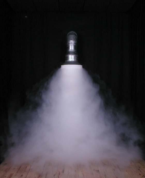
Zone 3
Zone 1
Zone 2 Near zone
Zone 1
The airflow in zone 1 is particularly reliant upon the cooling load per running metre of duct. A large cooling load results in a greater downward acceleration for the supply air in zone 1.
Zone 2
The near zone, which should not be used as a permanent workplace, is defined as the distance from the duct before the velocity is reduced to an acceptable level, depending on the comfort requirement. The length of the near zone is particularly dependent on the cooling load.
Zone 3
It is very important that the volume of air from the vertical low impulse system has been adapted to the cooling requirement and that the volume of air supplied is at least equivalent to or greater than the convection flows generated by the heat sources. This helps to achieve the best displacement effect and create a clean zone at the bottom and a polluted zone on top.
The vertical textile ducts supply fresh air directly in the occupied zone, which will obviously result in stratification in the ventilated room. This will cause a temperature gradient through the room, with the coldest air at the bottom and the warmest on top.
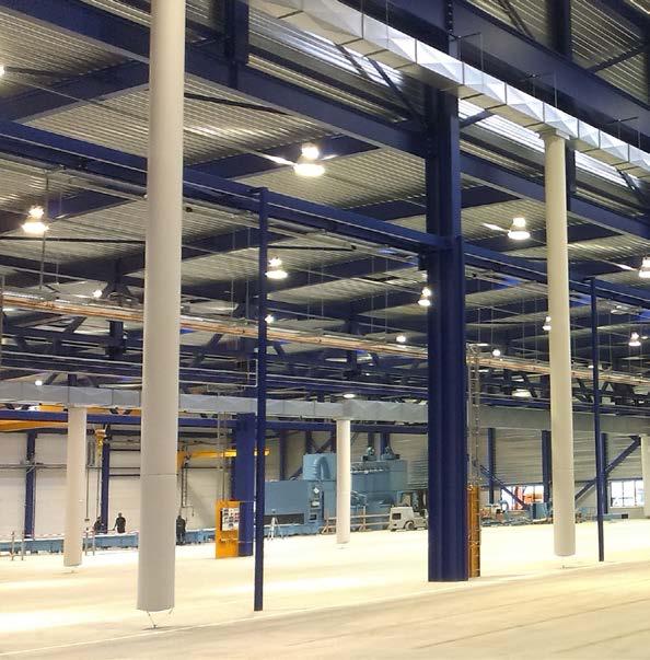
This can be used beneficially to reduce the cooling load as the cooling load removed from the room is directly proportional to the difference in temperature between the supply air and extracted air. If the air is extracted from the top of the room this will be warmer than the air in the room’s occupied zone, allowing the same cooling load to be removed from the room with a higher supply temperature.
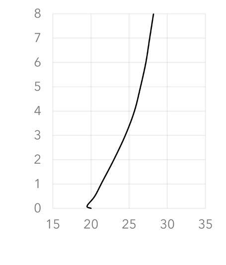
This results in energy savings when the cooling coil in the air conditioning unit is operating. It also means that free cooling can be used for longer periods of the year.
The required cooling load, combined with any comfort requirements, provides the basis for determining the volume of supply air and the supply temperature. To determine the necessary cooling load accurately, you need to calculate internal and external heat loads, while taking into account the heat accumulation in the building.
In the case of displacement ventilation, comfort requirements also include, apart from air velocity and air temperature requirements, the requirement for the maximum permitted thermal gradient in the occupied zone. KE Fibertec recommends that the maximum thermal gradient in the occupied zone does not exceed 1-2°C/m as any bigger difference may feel like a draught.
The vertical thermal gradient can be approximately calculated based on a so-called 50% rule, which states that half of the temperature rise from supply to extraction takes place at floor level, while the other half takes place between the floor and ceiling. Contact KE Fibertec’s development department for more information. Designing a ventilation system with vertical low impulse ducts requires considerable knowledge about the heat distribution in the premises. It is vitally important that the ventilation system is dimensioned correctly so that it takes into account the level of comfort in the premises’ work zones and the heat and polluted air are carried upwards and out of the occupied zone.
To displace the polluted air it is important that the volume of air supplied is at least equivalent to the total convection flow volume in the room. If this is not the case, the front of the polluted air will be dragged down towards the occupied zone, thereby reducing the effectiveness.
Many factors affect the size of convection flows in the room, such as the shape, area and surface temperature of the heat sources. But factors like the ambient temperature in the premises also have an impact. This is why it is often difficult to determine accurately the convection currents and table values must be used instead.
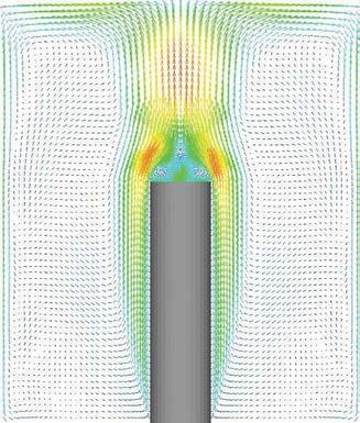
The figures below illustrate the typical flow pattern under a vertical KE-Low Impulse System in a heating scenario, ventilation scenario and two cooling
scenarios with a different cooling load per running metre of ducting.
∆T < 0°C
Delivering heated air short circuits the supply air, which means that the system is not suitable for heating. However, the heated air has a certain penetration, which initiates air circulation in smaller premises. As a result, the system can be used, to a certain extent, to heat the room before work begins or it is used.
∆T = 0°C
Delivering isothermal air produces a very diffuse flow pattern, which does not generate a powerful displacement effect. Systems are suitable, to some extent, for supplying replacement air.
∆T < 3°C
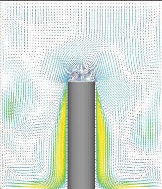
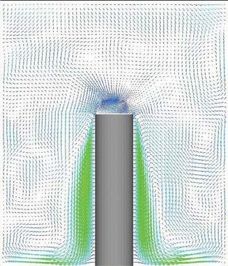
If slightly supercooled air is supplied the air will slowly drop towards the floor and be distributed evenly around the duct. In the event of heat-releasing activities and processes, the convection flows will entrain the supply air, thereby creating stratification in the room where the heat and pollution are drawn away from the occupied zone and extracted under the ceiling.

∆T > 5°C
If extremely supercooled air is supplied the air will quickly move towards the floor, thereby causing a greater risk of draught problems around the duct as the length and width of the near zone around the duct are increased. In the event of heat-releasing activities and processes, the convection flows will entrain the supply air, thereby creating stratification in the room where the heat and pollution are drawn away from the occupied zone and extracted under the ceiling.

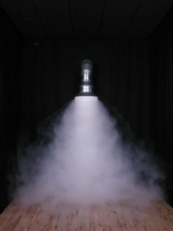


High Impulse Systems.
KEFibertecmarketstwoproductsfortextilebased high impulse ventilation: the KE-Inject System and KE-DireJet System. Both these systems can be produced in the form of round (Ø),half-round (D) or quarter-round (½D) ducts. The KE-Inject System comprises groups of holes in the textile duct, while the KE-DireJet System comprises rows of conical nozzles specifically for directional air distribution.
Product range: High impulse systems

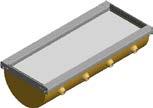
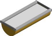
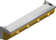
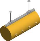


KE-Inject System


KE-DireJet System
1.8 m

Occupied zone
From a ventilation technology perspective, both the KE-Inject System and KE-DireJet System can be regarded as high impulse systems for mixing ventilation. For this reason, one general air distribution principle will be described for these systems, while the specific product features will be described separately.
KE-Inject System (½D) KE-Inject System (D)
Working zone
Occupied zone
Occupied zone for high impulse systems
As with low impulse ventilation, the occupied zone is not a standardised area, but a zone which is defined from one project to another in consultation with the architect and client. The occupied zone is often defined as the zone from the floor up to a height of 1.8 m above people who are in a standing position doing their job, while this height is set to 1.1 m for people who are seated.
Working zone for high impulse systems
In the case of industrial premises, it may also be appropriate for high impulse systems to divide the room up into a working zone as the state of the air may vary from the general level as a result of industrial processes. Heat and pollution sources are often present which require special measures to be able to maintain a satisfactory indoor climate in the working zone. If processes are carried out which cause extreme pollution, textile based ventilation should therefore be supplemented with local extraction vents.
Air distribution principle.
KE Fibertec’s high impulse systems are based on mixing ventilation and are characterised by the fact that air is delivered at a high velocity outside the occupied zone. The high air velocity rate in the air jet will generate excess pressure, resulting in an inflow and entrainment of room air towards the air jet supplied.
During the first air flow cycle the air velocity will be high, but as the volume of room air that becomes mixed increases, the air velocity will decrease. If the system has been dimensioned properly the delivered air volume will be completely mixed with the room air before it reaches the occupied zone and the air velocity rate has dropped to the desired level, depending on the room category. In a mixing ventilated room air velocities, air temperatures and humidity will be distributed identically and in theory, the air quality will be the same everywhere in the room.
A textile based high impulse system, unlike its low impulse counterpart, can be used for cooling, ventilation and heating. The reason for this is that KE Fibertec’s high impulses systems, unlike its low impulse systems, are less dependent on external effects, such as convective heat currents in the room. The supply air is delivered with high initial energy in the form of velocity (momentum) through holes or nozzles, with the effect that the air is discharged into the room instead of being distributed through a textile surface at low velocity. This means that KE Fibertec’s high impulse systems have what are known in flow engineering as a throw length and penetration length.
Compared with low impulse systems, the location of the exhaust grilles is only of minor significance to the air flows in the room. In practice, they are often positioned along the ceiling. The picture below illustrates the air distribution principle for high impulse ventilation.
Zone 1
The air is delivered at high velocity, often up to 15-18 m/s, through the holes (KE-Inject System) or nozzles (KE-DireJet System). This generates excess pressure in the centre of the air jets, resulting in an inflow and entrainment of the air in the room towards the air jet supplied.
Zone 2
As the volume of entrained air increases, the air velocity in the flow gradually decreases. The velocity decreases in inverse proportion to the distance from the duct.
Zone 3
In premises where a certain comfort level is required, the air velocity at the entrance to the occupied zone must be adapted to the conditions, which mainly depend on the level of activity of the people working there and what they are wearing (room category). To ensure that a suitable air velocity is achieved, the distance from the duct to the occupied zone must be greater than the calculated throw length (see definition on page 43).
Short circuiting warning.
It is important to be aware that mixing ventilation also entails a risk of the supply air being short circuited (accumulated under the ceiling). This problem may occur if overheated air is supplied combined with an excessively low discharge velocity, or if there are strong upward currents in the premises, preventing the air from reaching the occupied zone.
This problem becomes particularly apparent when the ∆T is more than 7-12°C. In the best case scenario, the poor heat distribution in the room can be compensated for by raising the supply temperature, but if the heating coil in the air conditioning unit does not have sufficient capacity to do this, the temperature in the occupied zone will fall. This situation is very inconvenient, both from an energy and comfort perspective.
To make sure that short circuiting is prevented, heated air must only be delivered if the supply temperature and discharge velocity are adjusted. This means that the warmer the supply air, the higher the discharge velocity needs to be to ensure that the air reaches the occupied zone. If the ceiling is particularly high (h > 8-10 m) the ducts need to be dimensioned for a high static pressure to be able to push the air down into the occupied zone. If this is not possible, the ducts can be positioned at a height of 5 metres, for instance.
Free jet
If the air jet is directed outwards into the open room, this is what is known in flow engineering as a free jet. The turbulent air jet entrains air from its surroundings and the jet’s diameter increases in proportion to the distance from the duct, while the velocity in the jet decreases.
Wall jet
If the air jet is directed towards a surface, this is what is known in flow engineering as a wall jet. The flow can be regarded as a bisected open jet as the surface can be regarded as a plane of symmetry. The maximum velocity is achieved close to the surface and is 2 greater than the equivalent velocity for an open jet at the same distance from the duct.
Free jets and wall jets.
A crucial factor for the air distribution principle behind the KE-Inject System and KE-DireJet System is the main direction of the air jets. If the jet is directed outwards into the open room, this is what is known in flow engineering as a free jet and if the air jet is directed at a surface, this is a wall jet. The difference between these two flow phenomena is their ability to entrain room air. If the jet is directed towards the ceiling surface it will try to “stick” to this surface because a negative pressure is generated between the jet and the ceiling as no replacement air can be
Throw length
The throw length is defined as the largest distance from the supply duct to a specific point in the premises where the air velocity is precisely equal to the desired final velocity, e.g. viso = 0.20 m/s. It is important to note that the throw length, by its definition, is valid in isothermal conditions. As a result, the calculations for air velocities must be corrected if the supplied air is either colder or warmer than the surrounding room air.


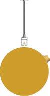

The throw length for a wall jet is 2 longer than for an equivalent free jet. The reason for this is that a wall jet will stick to the ceiling due to the Coanda effect and as a result, only half the volume of room air contributes to reducing the velocity rate.

supplied for the volume of room air entrained by the jet. This is known as the “Coanda effect” and it increases the throw length by a factor of in relation to the throw length for a free jet, while the velocity rate in the jet decreases proportionally more slowly. The air velocity needs to be a minimum of 0.35 m/s to be able to utilise the Coanda effect.
Thermal penetration length
The thermal penetration length is absolutely crucial in determining whether the air is actually distributed as expected. The theory underlying wall jets is actually based on the fact that the jet will not become so “heavy” that it will leave the ceiling’s surface before it is supposed to. If it does, the air velocity at the entrance of the occupied zone will be higher than calculated. This means that it will feel uncomfortable for anyone located in the zone affected by the jet. To prevent any drop of cold air, the thermal penetration length must be checked to see that it is at least 75% of the horisontal distance along the ceiling, L, where the air is moving.
minumum 0,75 x L L
minimum 0.75 x L
Using flow models.
Both the KE-Inject System and KE-DireJet System are highly flexible systems and any direction at all can be chosen for the air jets. It is obviously important for the air jets to point in the main direction of the air flow following the desired air flow pattern in the room. As mentioned earlier, it is also important that the air flow is directed downwards towards the occupied zone when heating is required in order to prevent short circuiting.
Apart from choosing the main direction for the air jet, secondary nozzle positions can be used. For instance, if the ceiling needs to be coated locally to avoid the formation of condensation or part of the area needs to be cooled down/heated, it is possible to direct individual nozzles or holes towards the relevant area. Nozzles can also be left out entirely in sections of the duct if no air needs to be supplied.
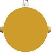
KE Fibertec uses three different flow models for textile based mixing ventilation in its everyday activities, which are flow models 1, 2 and 3 respectively. To be able to use KE Fibertec’s datasheets properly, you need to know which flow model is involved as all the datasheets have been specified for flow models 2 and 3, i.e. free jets. It is important therefore to clarify what the user wants and needs in terms of the system, as well as to become familiarised with processes and activities before starting to dimension the final design for the high impulse system.
Using flow model 1 (wall jet) can bring some benefit, even though the throw length increases as a result of the Coanda effect. Air jets tend to become more stable when cooled air is delivered, while the risk of a drop of cold air or draughts in general in the occupied zone is kept to a minimum.
The Coanda effect also makes the blanket of air “stick” to the ceiling, which means that it will not be deflected by local heat sources, obstacles etc. Consequently, there is a greater likelihood of achieving the desired flow pattern in reality than with delivering an free jet. As was mentioned before, it is recommended to use flow model 2 or 3 for both the KE-DireJet System and KE-Inject System if the system is going to be used to provide heating. This will then eliminate the risk of the supply air being short circuited.
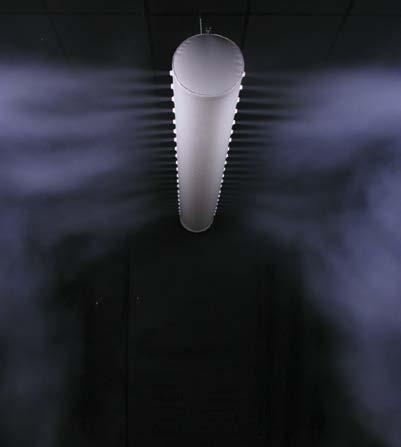
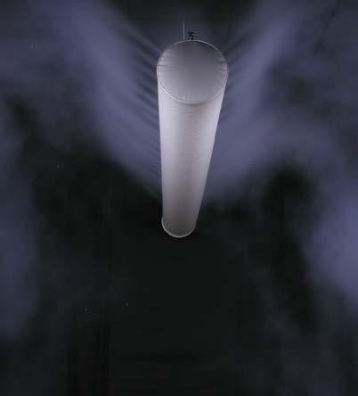
All KE Fibertec’s textile based ventilation solutions are 100% customised. Any direction can be chosen for the holes in the KE-Inject System and for the nozzles in the KE-DireJet System. Depending on the system’s usage, the holes/nozzles can be pointed in any direction, specified at an angle from 12 o’clock.
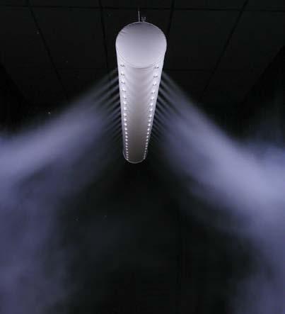
KE-Inject System
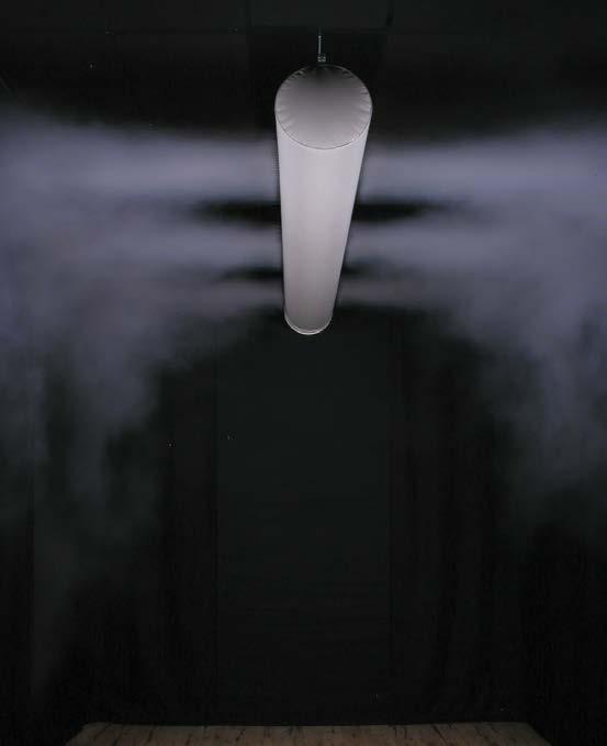
The KE-Inject System offers so much flexibility. It has been upgraded with a new family of multiple sized laser cut holes. The Inject system is divided into four families. The conventional Inject system consists of three different groups of fixed patterns (LV, MV and JET) all made with small Ø4 mm holes for comfort solutions.
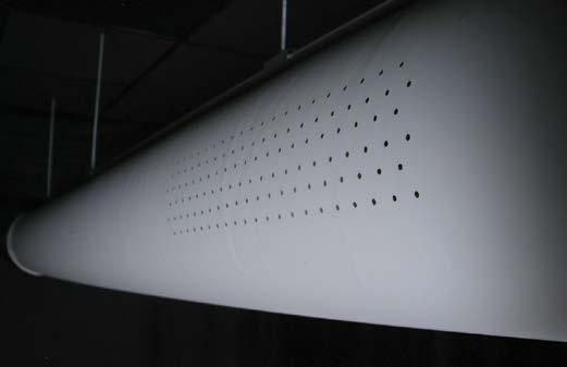
The new Inject Flex family comprises three different groups (S, M, XL) of customised hole sizes. The Inject Flex S has a hole diameter of 4 and 6 mm. Inject M comes with hole sizes from 6-25 mm, and the long throw Inject XL family comes with hole sizes from 35-70 mm diameter.
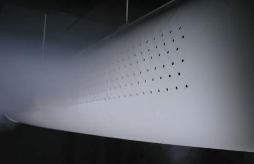
The KE-Inject System comprises small holes in coated textile material (airtight). The delivery of air through the holes causes induction of the room air on a large scale, resulting in a relatively rapid reduction in the air velocity rate in the jet compared to the KE-DireJet System.
KE Fibertec markets three types of conventional Inject products (LV, MV, JET) with their characteristic patented hole design running in pattern sections along the duct’s longitudinal surface.
The special hole pattern produces an excellent induction effect where the secondary room air is mixed very fast, which reduces the air velocity in the jet and thereby the risk of draughts in the occupied zone.
KE Fibertec has well-documented measurements of pressure loss, throw lengths and air penetration for the three conventional Inject types where the final design is based on the these hole patterns. If the system layout requires more design flexibility, KE Fibertec recommends the KE-Inject Flex System.
Conventional KE-Inject (LV, MV, JET).
The special hole design produces an extremely good injection effect, i.e. the air jets operate like a row of small missiles. The high velocity rate generates a relatively large amount of low pressure behind the jets, which is crucial to the inflow of room air from zones around the KE-Inject duct.
The injection effect can be improved further if the air jets are directed towards the ceiling because the inflow of room air is reinforced as the heat naturally rises upwards in the premises. Another benefit from grouping the holes in a particular design is the opportunity it provides to control the flow. The air jets from the many holes will see their angle of propagation continually increase as room air is entrained and mixed. After a short time the air jets will converge and continue like a single blanket of air.
If the holes are grouped with a large distance between them a larger volume of room air needs to be mixed before the air jets converge and form an air blanket than if the holes are placed in a hole design with a small distance between them. As the drop in velocity in the jet mainly depends on how much room air is mixed in, it is obvious that KE Fibertec can control the flow very precisely by changing the hole design.
If the requirements are for short throw lengths and a large mixing capability, a KE-Inject Low Velocity System is used, with a large distance between holes in the groups of holes. Similarly, the KE-Inject JET System is used with a small distance between the holes if the blanket of air has a larger stretch to overcome. In these situations the KE-DireJet System is also ideal.
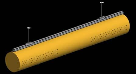
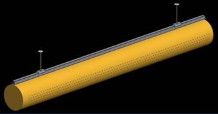
KE Inject Low Velocity (LV)
Hole size: Ø4 Suitable for both heating and cooling Extremely high induction effect (up to 15x) Hole sections divided 50/50% per m Air flow: 11.5 m3/h per m at 120 Pa (1 row)
KE Inject Medium Velocity (MV)
Hole size: Ø4
Suitable for both heating and cooling High induction effect Hole sections divided into 75/25% per m Air flow: 18 m3/h per m at 120 Pa (1 row)
KE Inject Jet (JET)
Hole size: Ø4
Suitable for both heating and cooling
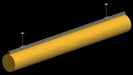
Efficient for spot or close-up ventilation
Holes 100% - no sections (similar to a linear slot diffuser)
Air flow: 23 m3/h per m at 120 Pa (1 row)
KE-Inject Flex (S, M, XL).
KE Fibertec has introduced a new flexible Inject family called Inject Flex. Unlike the conventional Inject family made with sections of hole patterns, the Inject Flex system can be made with an almost unlimited configuration with multiple patterns and orientations to perform in every environment from comfort to industrial.
At the same time, the Inject Flex can be made of every available customised material from KE Fibertec so that the flow pattern can be combined in an endless configuration, including a Cradle to Cradle certified solution.
How it works.
KE Fibertec’s Inject system functions by supplying air into the room at a high velocity in the primary jet. The supply air mixes with room air, gradually reducing the air velocity prior to entry into the occupied space.

As the number of holes per metre may vary, all jets will impact on each other. With only one or a few holes per metre, the individual jet will act like a circular 3-dimensional jet, but with the maximum number of holes per metre, the air flow will change character to a 2-dimensional jet. The Inject Flex system can also be configurated as a linear slot diffusor. These different design factors have already been taken into account in KE Fibertec’s TBV Designer software.
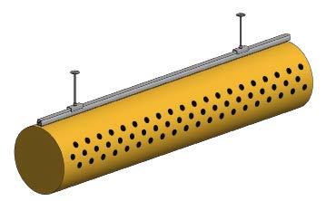
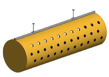
KE Inject Flex S
Hole size Ø4 and Ø6 mm Made with 21 holes or 42 holes per metre
Suitable for both heating and cooling
Air flow: 0.5-1 m3/h per hole at 120 Pa
Short throw lenghts
KE Inject Flex M
Hole size Ø6, Ø12 and Ø25 mm
Made with 1-14 holes per metre
Suitable for both heating and cooling
Air flow: 1-15 m3/h per hole at 120 Pa
Medium throw lengths
KE Inject Flex XL
Hole size Ø32, Ø50 and Ø70 mm
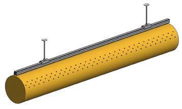
Made with 1-6 holes per metre
Suitable for both heating and cooling
Air flow: 30-130 m³/h per hole at 120 Pa
Long throw lengths
Product features of KE-DireJet Systems.
The key difference between the KE-Inject System and KE-DireJet System is their ability to entrain room air. The KE-DireJet System is made of a coated or permeable textile material with rows of conical nozzles for 100% active, directional delivery.
The conical nozzles limit the induction of room air around the individual air jet, whereby the velocity in the jet decreases relatively slowly compared to the KE-Inject System. As a result of this, both the throw length and thermal penetration length are extended considerably for the KE-DireJet System.
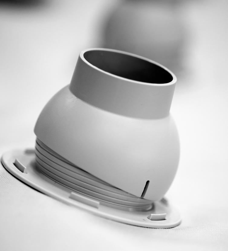
KE Fibertec is the only distributor of textile ducts that offers five different nozzle sizes: Ø12, Ø18, Ø24, Ø48 and Ø60 mm. The flexibility in the choice of nozzle size offers great benefits as the KE-DireJet System can be used in virtually every type of premises that requires mixing ventilation, even in extremely large premises, such as high-bay warehouses or large sports arenas.
The nozzle size and flow model naturally depend on the requirements specification for the ventilation system, and KE Fibertec will obviously advise on the best choice of nozzle size and direction. Ducts are often used with different nozzle types and flow models in the same duct. This allows you to achieve the flow pattern and air intensity in the various zones exactly how you want.
The conical nozzles are fitted in holes made of coated polyester fabric and are secured using a locking ring. The maximum number of nozzles per row per metre is 14 for the Ø12, Ø18 and Ø24 mm nozzles. If this is not sufficient, it is recommended using two or more rows of nozzles.
In the case of Ø48 mm and Ø60 mm nozzles, it is recommended using a maximum of six nozzles per metre. As the number of nozzles per metre is increased, the individual jets will have an impact on each other and they will change character from circular jets to 2-dimensional jets.
The velocity rate in the flow will also slow down as the induction of room air is limited the closer the nozzles are placed together. These factors are naturally included in KE Fibertec’s datasheets.
The nozzles can be supplied with nozzle plugs to block the air flow temporarily in certain zones. This is used most often in cases where the system’s features need to be changed for a period of time, for instance, if the premises’ use changes.
The KE-DireJet System is often used in large premises with large throw lengths. The choice of nozzle depends on the system’s performance, the relevant room and the indoor climate requirements.
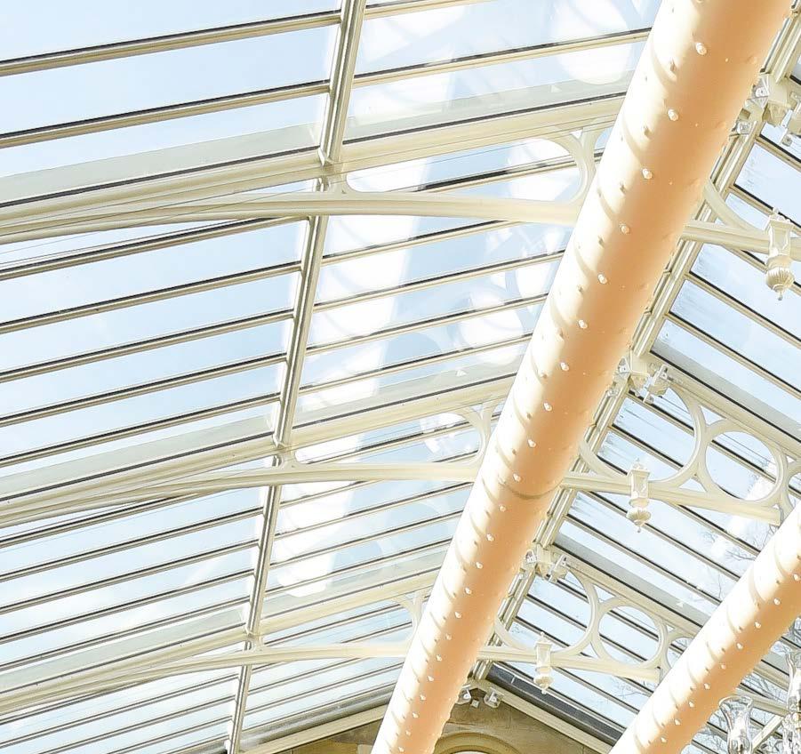
Ø12 mm nozzle

The Ø12 mm nozzle is used where directional delivery is required in a room and comfort requirements are important. Each nozzle delivers 5 m3/h with a static pressure of 120 Pa. See datasheet 16 for further information.
Ø18 mm nozzle
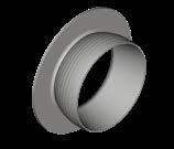
The Ø18 mm nozzle is used where directional delivery is required and often in process-orientated solutions, in a room where relatively large throw lengths are required. Each nozzle delivers 11 m3/h with a static pressure of 120 Pa. See datasheet 16 for further information.
Ø24 mm nozzle
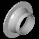
The Ø24 mm nozzle is used for directional delivery in a room with large throw lengths. Each nozzle delivers 20 m3/h with a static pressure of 120 Pa. See datasheet 16 for further information.

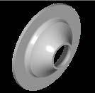
Ø48 mm nozzle (DireJet Vario)
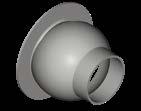

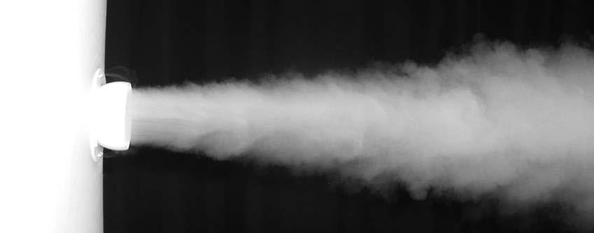
The Ø48 mm nozzle is used for directional delivery in a room with very large throw lengths. The flexible nozzle can be turned 30° in any direction around the nozzle’s centreline. Each nozzle delivers 81 m3/h with a static pressure of 120 Pa. See datasheet 17 for further information.
Ø60 mm nozzle
The Ø60 mm nozzle is made up of the bottom of the Ø48 mm nozzle and is used for directional delivery in rooms with very large throw lengths. Each nozzle delivers 139 m3/h with a static pressure of 120 Pa. See datasheet 17 for further information.
KE-DireJet Vario - The flexible solution
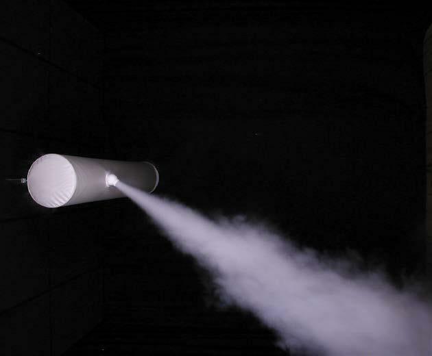
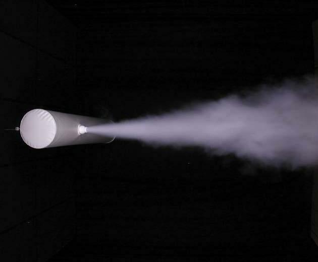
The latest development of the KE-DireJet System is called KE-DireJet Vario. It is a multi-adjustable nozzle that allows the direction of the air jet to be freely adjusted up to 30° in any direction in relation to the nozzle’s centreline.
When dimensioning a system, KE Fibertec takes as its starting point the room’s layout and function so that the nozzles are basically placed in the correct position (nozzle adjustment 0°).
The KE-DireJet Vario nozzle can be adjusted manually so that the main direction of the air jets can be changed by up to -30° in relation to the nozzle’s centre line. This may be particularly appropriate if the room’s layout is changed after installing the system. This nozzle adjustment can also be used in situations where a large cooling load needs to be supplied in the room.
The manual adjustment can also change the main direction of the air jets by up to +30° in relation to the nozzle’s centre line. As mentioned above, this may be particularly appropriate if the room’s layout is changed after installing the system. This nozzle can provide great benefit if it is used in situations where a large heating load needs to be supplied for the room.

Hybrid Systems.
It was previously mentioned that both the KE-DireJet System and KE-Inject System can be regarded as active mixing systems, but this is not necessarily their only function. KE Fibertec AS uses laser technology to facilitate production of more advanced product versions, where passive low impulse ducts can be made more active by laser cutting a number of small holes or inserting nozzles in the textile material.
The more holes or nozzles the system has, the more active the textile ducts will obviously become. This will change how the system works from a passive low impulse system to an active mixing system or what is known as a hybrid textile duct.


Product range: Hybrid systems
KE-Inject Hybrid System
KE Fibertec markets two products for textile based hybrid ventilation: The KE-Inject Hybrid System and KE-DireJet Hybrid System. These systems are also produced in the form of round (Ø), half-round (D) or quarter-round (½D) ducts. From a ventilation technology perspective, the KE-Inject Hybrid System and KE-DireJet Hybrid System can be regarded as a combination of active high impulse ventilation and passive low impulse ventilation.
KE-Inject Hybrid System (D)
KE-Inject Hybrid System (½D)
KE-DireJet Hybrid System
KE-DireJet Hybrid System (D)
KE-DireJet Hybrid System (½D)
Occupied zone
1.8 m
Occupied zone for hybrid systems
As with low impulse ventilation, the occupied zone is not a standardised area, but a zone which is defined from one project to another in consultation with the architect and client.
The occupied zone is often defined as the zone from the floor up to a height of 1.8 m above people who are in a standing position doing their job, while this height is set to 1.1 m for people who are seated.
Air distribution principle.
In a nutshell, hybrid systems comprise low impulse ducts which are made active by using holes or nozzles. As a result, the low impulse principle is combined with the high impulse principle, whereby part of the air volume in the system is distributed away from the near zone under the ducts.
This offers in particular obvious benefits if cooling is required where ΔT is higher than 5-6°C, as it helps avoid an immediate “cold drop” under the ducts. Instead the cooling load is distributed across a larger area in the room. Hybrid product versions therefore require air velocities etc. to be calculated for both the low impulse and the high impulse section. It must also be ensured, of course, that the air flow from each of these systems does not contribute to any discomfort in the room.
Manufacturing hybrid systems opens up a new world of flexibility, but it is also of paramount importance that you are aware of the requirement specifications for the ventilation system.
Just a few rows of holes or nozzles can change the flow from a passive low impulse system to an active mixing system. But the major benefits of this new technology are that you can, in theory, actually dimension one and the same system to be passive in some zones and more or less active in others.
Hybrid systems are absolutely ideal for ensuring that optimum air distribution is achieved in systems with both cooling and heating requirements, as a textile duct with holes or nozzles gives the air energy in the form of movement, as has already been mentioned. This means that air currents are not only reliant upon thermals, as is the case with a low impulse system.
On the other hand, the air which passes through the textile will not make any significant contribution to air distribution in a system for heating. But the air which passes through the textile material does not disappear and short circuit under the ceiling. The majority of it will instead be entrained by the air jets which pass through the holes or nozzles.
Zone 1
The air is delivered partially at high velocity through the holes or nozzles and at low velocity through the textile material. The excess pressure in the centre of the air jets generates an inflow and causes entrainment of room air, as well as part of the duct’s own air. The air’s acceleration under the duct (low impulse flow) is particularly reliant upon the cooling load per running metre of ducting.
Zone 2
The warmer room air is displaced by the cooled air from the duct under the hybrid duct. Part of the low impulse flow is entrained into the high impulse flow. The velocity gradually decreases in the high impulse flow. The velocity decreases in inverse proportion to the distance from the duct.
Zone 3
When entering the occupied zone, it is important to ensure that both the air velocity in the low impulse flow and the air velocity in the jet originating from the holes or nozzles have been adapted to the conditions so that the room’s comfort requirements are met.
Zone 1
Zone 2
Zone 3 1.8 m
Hybrid solutions for enhanced comfort.
The job of hybrid textile ducts, as was explained on the previous page, is to shift part of the air volume away from the area under the duct. If you compare this to a low impulse system, a greater cooling load per running metre can therefore be added without generating a draught under the duct.
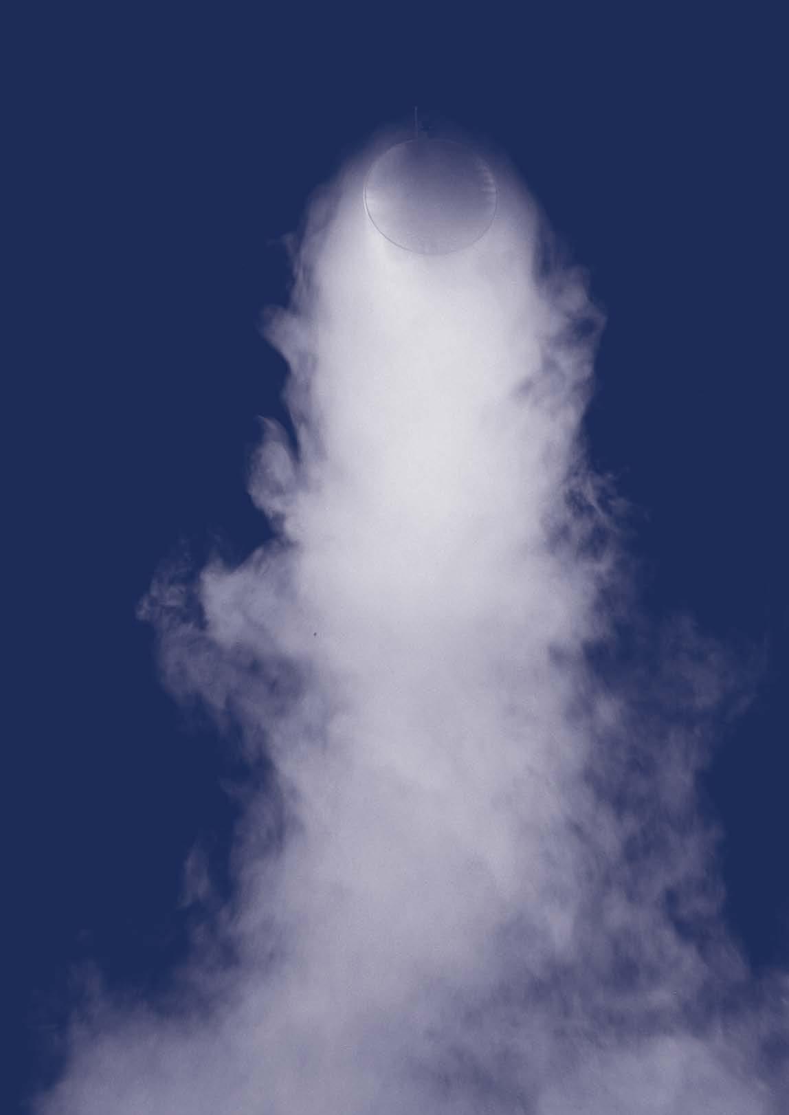
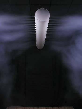
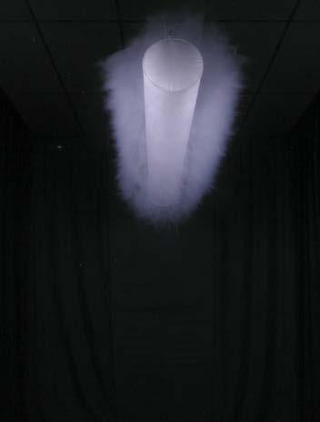
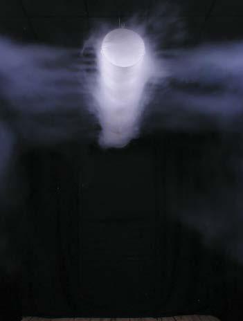
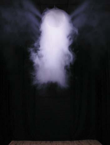
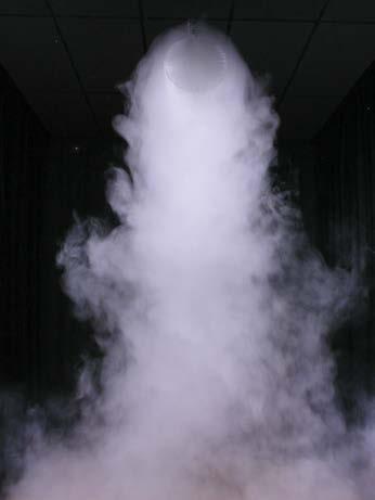
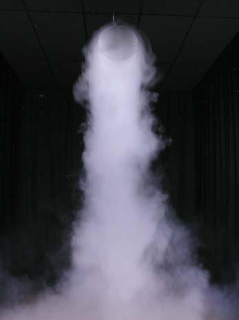
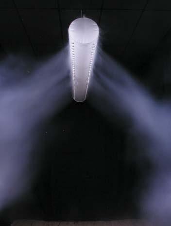
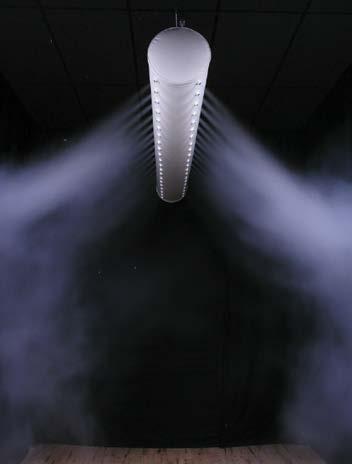
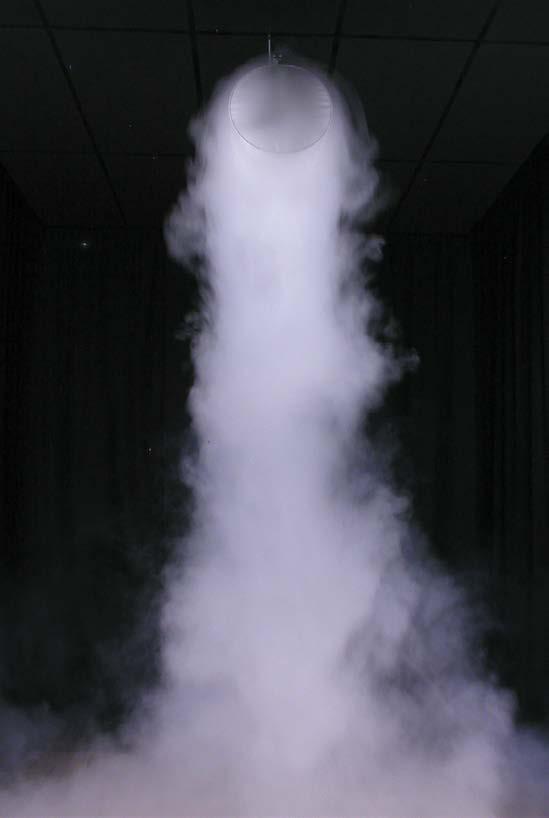
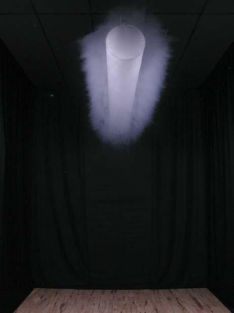
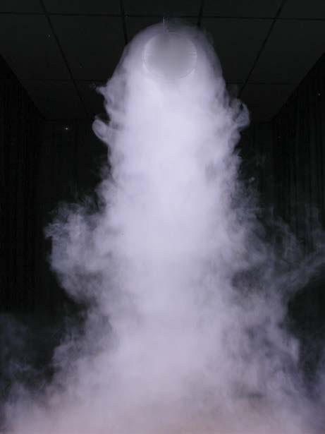
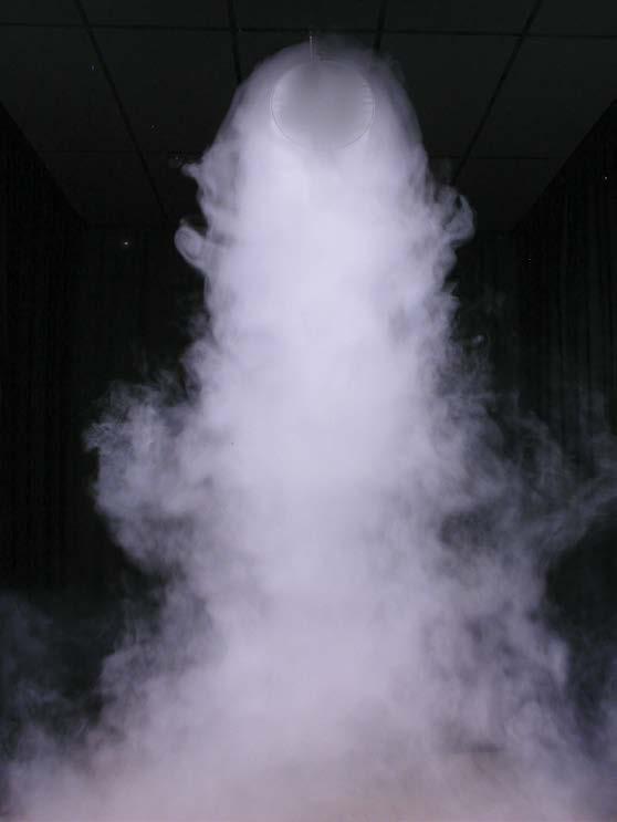
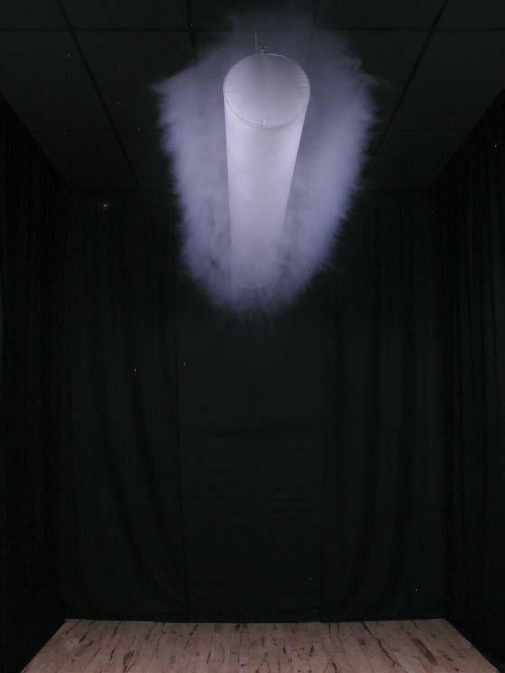
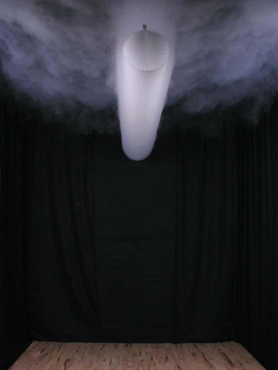
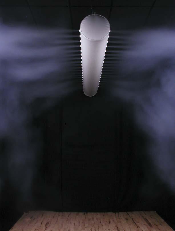
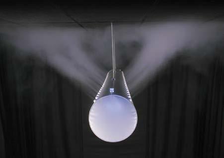
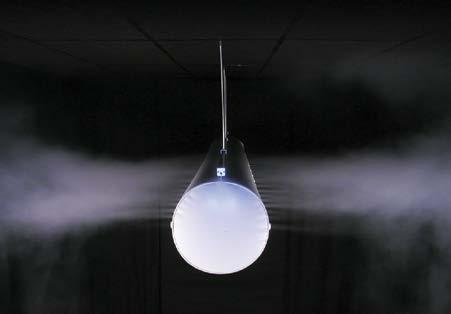
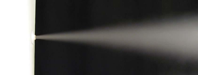
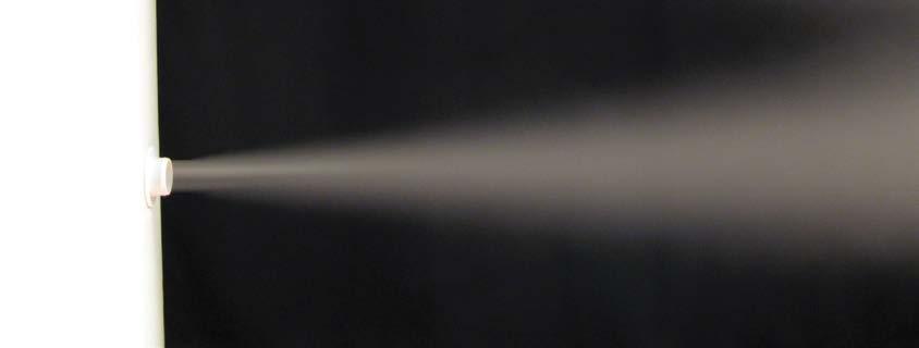
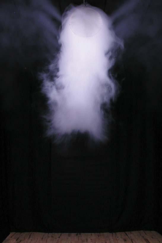
The pictures below show a smoke test where a comparison is carried out between a low impulse system and a KE-Inject System with 20% of the air passing through the holes. Both systems are supplied with the same volume of air at a ∆T of 5°C. It can be clearly seen from the density of the smoke in the near zone under the textile duct what a large difference there is in air velocity under the duct. It is obviously important to remember that the throw length for the air passing through the holes must be sufficient to prevent draught problems in the occupied zone.
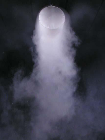
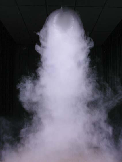
“Smoke test comparing a KE-Low Impulse System and a KE-Inject Hybrid System. It can be clearly seen from the density of the smoke in the near zone under the textile duct what a large difference there is in air velocity under the duct. It is obviously important to remember that the throw length for the air passing through the holes must be sufficient to prevent draught problems in the area where the high impulse flow penetrates the occupied zone.”
Changing the number of holes/nozzles in the textile material helps to combine high impulse systems with the low impulse principle, which means that basically three different types of flow patterns can be obtained.
Even a distribution between the textile material and nozzles/holes of 60/40 completely alters the way in which the system operates, from a passive thermal low impulse system to an active mixing system. Even if the distribution between the textile material and holes/nozzles is changed to 0/100, this does not make the flow pattern look noticeably different.
Type of duct Air through holes/nozzles
Low Impulse System 0%
Hybrid System 5-10% upwards
Flow pattern Purpose
The air drops down right under the textile duct in cooling mode
The air drops down directly under the textile duct
Hybrid System 15-30% upwards/side Part of the air volume drops. Spread 2-3 m
Hybrid System > 40%
Passive thermal displacement/low impulse
Coating of ceiling due to condensation problems
Spread of near zone when cooling > 5-6°C
The air spreads in the main direction of the holes Active high impulse system
As can be seen from the table on the opposite page, the number of holes or nozzles per metre of ducting has a major impact on whether the delivery will be diffuse or come from a particular direction.
Model A (5-10% through holes/nozzles)
KE Fibertec therefore splits the hybrid systems according to three main principles: model A, model B and model C.
When model A is used, the delivery is very diffuse, similar to low impulse currents. Model A is used especially in premises with high comfort requirements, i.e. room category A+B. The high impulse principle can be beneficially combined with the diffuse flow pattern from low impulse systems if, for instance, there are periods when there is need for heating or the need for more directional ventilation above a particular machine or process. Furthermore, condensation problems on the ceiling in humid premises can also be rectified by simply placing a very small number of hole rows or nozzles, pointing towards the surface of the ceiling.
Model B (15-30% through holes/nozzles)
When model B is used a combination delivery is largely obtained between holes/nozzles and textile materials. Part of the volume flow will in a cooling scenario always drop below the duct, but most of the air is distributed according to the main direction of the holes or nozzles. The combination solution is typically used in premises where there are requirements for both cooling and heating, but with fairly high requirements for comfort in the room, i.e. category B+C.
Model C (>40% through holes/nozzles)
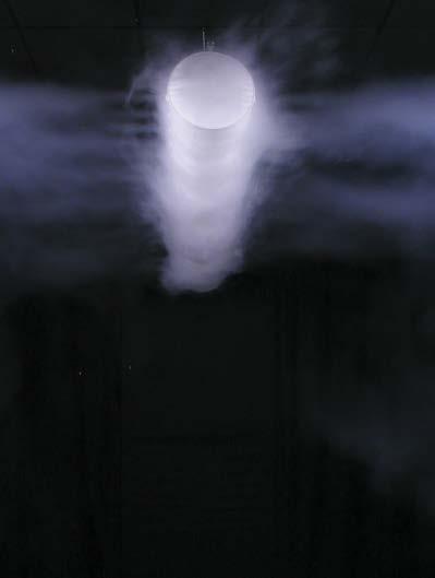
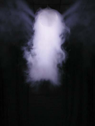
Model C is used for highly directional delivery, which is often used with process-oriented solutions or in large premises, such as sports centres. The air will only be distributed in the main direction of the holes or nozzles, which is the case with KE Fibertec’s conventional high impulse systems. Directional air distribution through the holes/nozzles is incredibly effective and the flexible positioning of the hole rows and nozzles can, in a sense, meet every function in larger rooms.

FBS Panels.
Having to create healthy indoor air quality in rooms of low ceiling height can be a challenge. Indoor climate considerations may conflict with the desire to create an aesthethic solution that does not detract from the appearance of the room.
The FBS ceiling panels are integrated into the ceiling and are available in a number of colours allowing them to discretely blend into the architecture without taking up space. In other words it is a spacesaving solution where every square metre counts.
Diffuse or directional ventilation.
KE Fibertec’s FBS ceiling panels that have been developed with the support of Aalborg University counteract poor indoor air quality by means of either diffuse or directional ventilation.
FBS ceiling panels are suited for i.e. schools, offices, and various comfort environments and are designed to operate at a lower level of air pressure than standard ceiling diffusers. This makes it a more energy-efficient solution - helping to limit both operational costs and the environmental impact.
Why choose FBS ceiling panels?

• Fully integrated in suspended ceilings
• Quick and easy installation and maintenance
Occupied zone
Room height
The FBS ceiling panels for diffuse or directional ventilation ensure air distribution free of draught as well as a low pressure loss and sound pressure level of less than 20 dB(A).
Flexible air delivery.
The system ensures that the entire textile surface is actively used for air distribution. The results are very low supply air velocities and air distribution free from draught. Also, the patented laser cut hole pattern provides flexibility so that air is spread over a larger area.
The system is lightweight and easy to install without the use of any tools. Besides being easy to clean and maintain it is made of a fire-retardant fabric that meets international fire standards.
• A flexible solution that is supplied as single panels or combined into a set of panels to form a pressure chamber (up to four panels)
• Available in standard and special colours
• Standard articles for delivery at short notice
The FBS ceiling panels are available separately and can be combined to create a pressure chamber (up to four panels) without unnecessary pressure loss.
Suitable for rooms with low ceilings.
The panel top is made of textile material and therefore flexible. That makes a panel solution ideal for rooms with limited headroom above the ceiling and for rooms with low ceilings. In addition, the panels are fully integrated in the ceiling.
Types.
The panels are made in sizes 600x600 mm, 625x625 mm, and 1200x600 mm for standard suspended ceilings and come with a flexible socket Ø160-250 mm. 600x600 and 625x625 panels always come with a socket at the end of the panel.

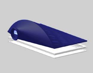


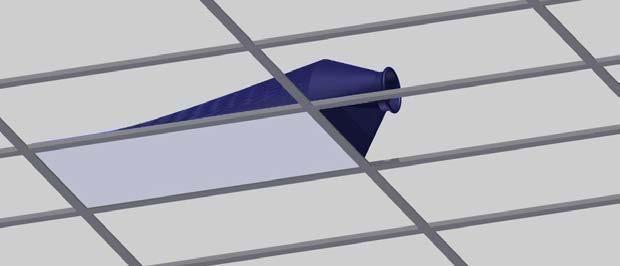

1200x600 panels come with a socket at the side or at the end of the panel. All sizes are available in a version that by means of zippers offers combination options with up to four panels. The panel does not require more room above the ceiling than the socket.
Due to the low weight of the panels any additional ceiling suspension is unnecessary, and the panels are installed in the same way as a traditional ceiling. Combi
Design example.
600x600
Example: Type 1 (775) - 600x600
A pressure of 35 Pa and ΔT -2°C will generate an air volume of 100 m³/h, a velocity in the occupied zone of 0.17 m/s, and a sound power level of <10 dB(A), which means that this solution is consistent with the criteria of room category A acc. to EN 1752. Type 2 with baffles will generate a sound power level of 14 dB(A).
Pressure [Pa] Pressure [Pa] Pressure [Pa]
90
80
70
60
50
40
30
20
10
100 0 100 200 300 400 500 600 700 800 900 1000 550 775 1240
0
90
80
70
60
50
40
30
20
10
> > 0
100 0 00 0 05 0 10 0 15 0 20 0 25 0 30 0 35 550 775 1240
90
80
70
60
50
40
30
20
Occupied zone Room height See more in datasheet 26
10
ΔT -2°C ΔT -5°C > > 0
Air volume [m3/h] Velocity [m/s] Sound Power Level [dB(A)]
100 10 20 30 40 Type 1
1200x600
Example: Type 1 (775) - 1200x600
A pressure of 40 Pa and ΔT -5°C will generate an air volume of 200 m³/h, a velocity in the occupied zone of 0.25 m/s, and a sound power level of 13 dB(A), which means that this solution is consistent with the criteria of room category B acc. to EN 1752.
Occupied zone Room height
90
80
70
60
50
40
30
20
10
> >
Pressure [Pa] Air volume [m3/h]
100 0 100 200 300 400 500 600 700 800 900 1000 550 775 1240
0
ΔT -2°C ΔT -5°C
90
80
70
60
50
40
30
Both examples are based on a room height of 2.5 m and an occupied zone of 1.8 m equivalent to a person standing upright. 0
>
20
10
Velocity [m/s]
>
90
80
70
ΔT -2°C Pressure [Pa] Pressure [Pa]
60
50
40
100 0,00 0,05 0,10 0,15 0,20 0,25 0,30 0,35 550 775 1240 > >
30
20
10
0
Sound Power Level [dB(A)]
100 10 20 30 40 Type 1
See more in datasheet 26
Single components.
The FBS Panels consist of three single components that can be easily disassembled and replaced, if needed, without the use of special tools. The flexible product structure makes it easy to change the design if the panels must be moved to another position in the ceiling.
If the top part no longer fits in relation to the supply air duct, you can order a new top part and replace it with another type.
The same goes for the bottom. It can be easily removed and washed, or you can freshen up the design with a new bottom without having to buy a brand new panel.

The FBS Panels can also be used as a 100% diffusion ceiling, ie. where the air is blown into the chamber above the suspended ceiling to diffuse out through the air-permeable panel. In that case, you deselect the top part and only the frame and bottom part are delivered.
Bottom Type 1 / Type 2
Installation.
It is important that the FBS Panel can be laid unhindered in the suspended ceiling and rest on the profiles that support the ceiling panels. In this way the FBS Panel will be flush with the ceiling panels.


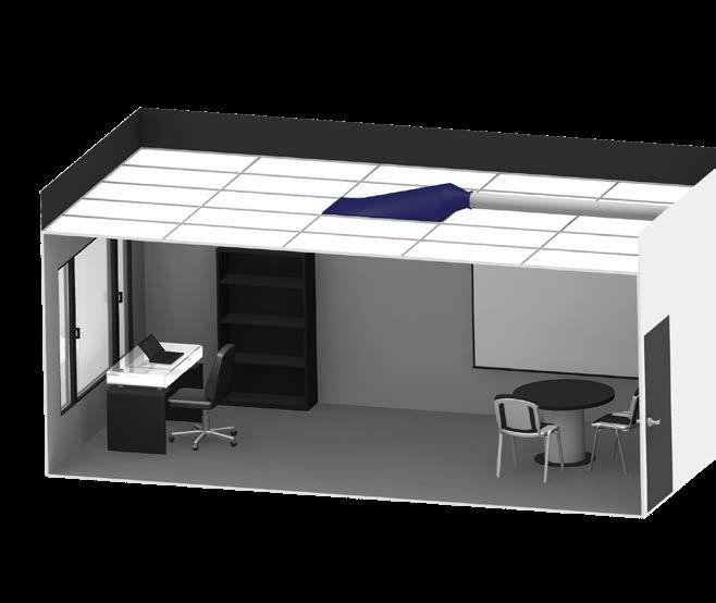
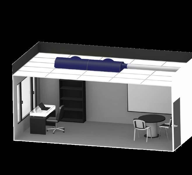

Do not use tools and do not apply force when placing the panel.
See list of approved suspended ceiling types at ke-fibertec.com. 1
Colours.
CRADLE TO CRADLE MATERIALS / COLOURS PANTONE / RAL
WHITE 11-0601-TP / 9010
TM
YELLOW 14-0955-TP / 1028
BLACK 19-5708-TP / 9005
LIGHT GREY 12-4705-TP / 9002
DARK GREY 17-4402-TPG / 7042
DARK BLUE 19-3864-TP / 5002
RED 18-1655-TP / 3031
TM TM
BIM.
Many consulting engineers and installers use Revit to design ventilation solutions. KE Fibertec has developed a plugin for Revit and can offer a wide range of duct systems as BIM components to suit all your project building applications so you are able to send the design directly from the user to and from KE Fibertec.
If you need any assistance, please view the user guide at www.ke-fibertec.com that will outline the step-by-step process. The plugin comes with KE families which are automatically loaded into Revit.
www.ke-fibertec.com/download
Washing.
For washing of the panels only the visible part (bottom) is to be removed from the panel. Tools are not needed. The textile material should be washed at 40°C according to the washing instructions for the material.
Warranty.
FBS ceiling panels are covered by a 10-year product warranty that covers both materials and operation.
See KE Fibertec’s warranty conditions at ke-fibertec.com or contact us for more info.
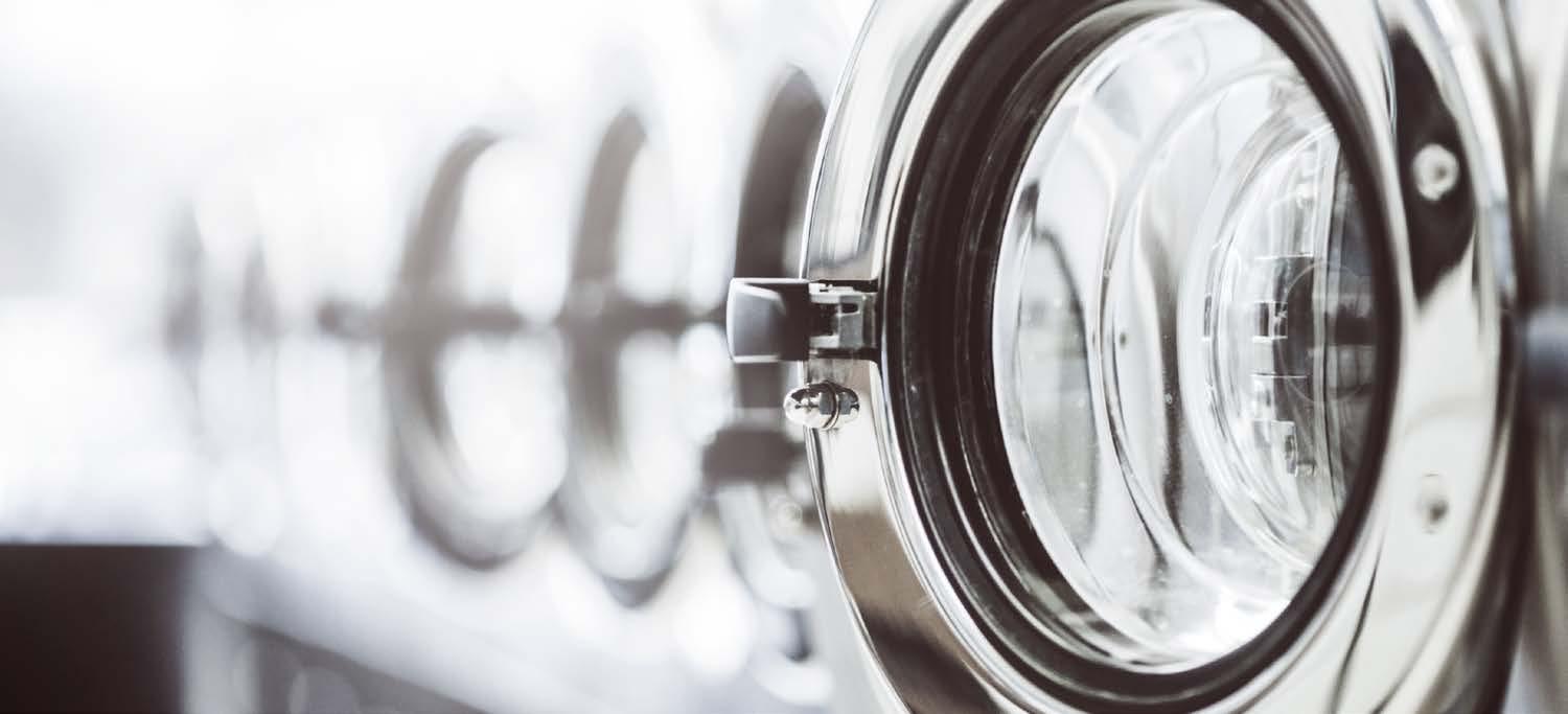
Suspension Systems.
Among the advantages of KE Fibertec’s suspension systems are the rails cut to size, which saves time at the construction site, and the aluminum rails are easy and quick to mount in almost all types of ceilings.
The low weight of both rails and textile ducts also provide ergonomic advantages compared to steel ducts.


Suspension.
KE Fibertec’s TBV systems can be supplied with different suspension systems which can be fitted to any type of ceiling. What all the suspension systems have in common is that they are supplied cut to the same length as the textile duct.
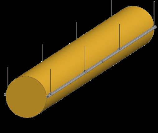
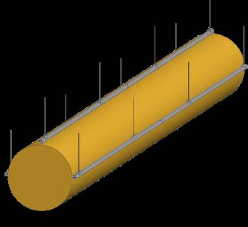
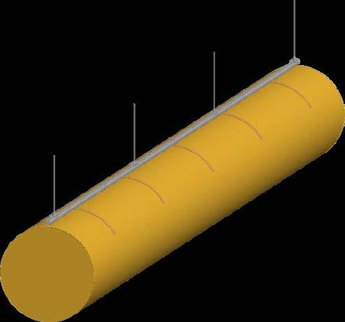
They are also packaged with the necessary fixing components and a label specifying where they are meant to be installed. See installation instructions and other information at ke-fibertec.com.
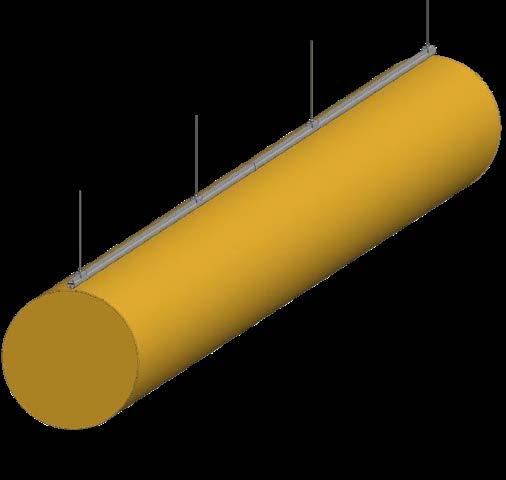
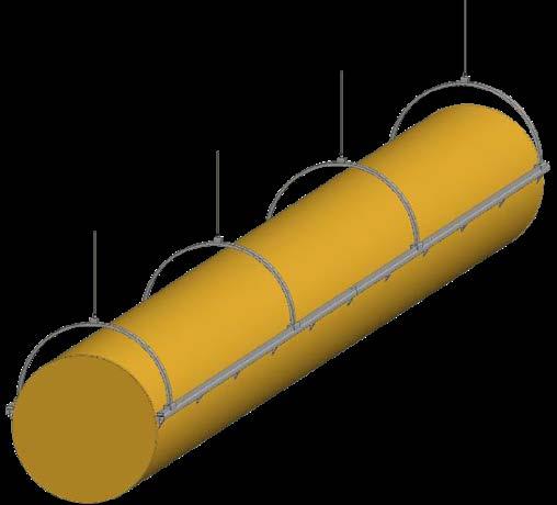

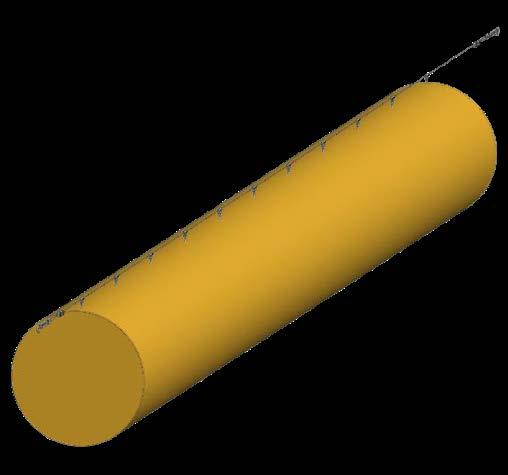
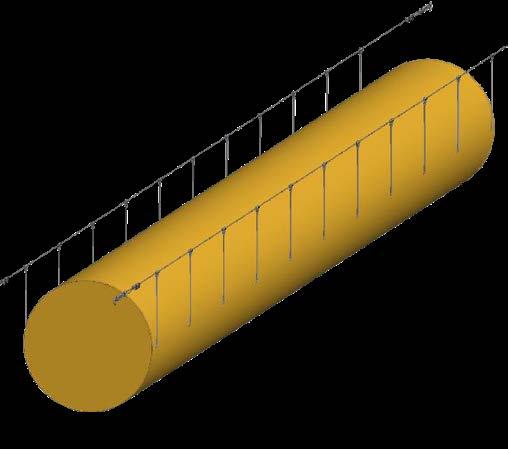
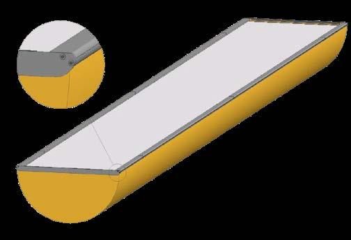

Suspension systems.
KE Fibertec’s TBV systems can be supplied with different suspension systems which can be fitted to any type of ceiling. What all the suspension systems have in common is that they are supplied cut to the same length as the textile duct. They are also packaged with the necessary fixing components and a specific label indicating where they are meant to be installed. See also the installation instructions and other information at ke-fibertec.com.
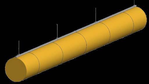

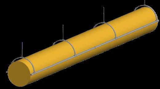
Our textile materials weigh 260-330 g/m2 which is much lighter than metal spiral ducts. Additionally, textile ducts are much easier to handle and transport as they are folded and packed in cartons of a maximum weight of 25 kg.
Safetrack Arches. Dual Arch
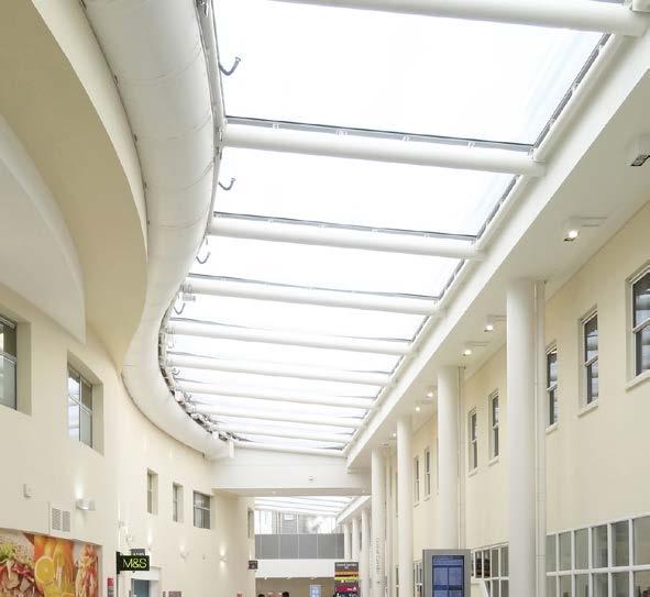
Dual Arch mounting brackets utilise the stability of double rails and at the same time they are quick and easy to install. Large textile ducts will be stably suspended both with and without air and installation time is reduced considerably as the ducts are mounted in a single ceiling rail.
Curved textile ducts.
Product development of the TBV design now enables us to offer curved textile ducts designed for a specific radius (min. 12 metres) and with Safetrack rails that conform to the shape of the duct. This product can naturally be combined with both ordinary passive low impulse systems and with our hybrid solution in which the low impulse system is made with lasercut inject holes. A good example is above system that KE Fibertec delivered to Broomfield Hospital in Chelmsford, England.
Duct Arch
Duct Arch is a pre-bent aluminium rail mounted in hidden sewn-in pockets in the TBV ducts. The Arches reduce sagging when the air is off and prevent popping with ON-OFF start. The unique Safetrack is designed in a way so that the Arch brackets are easily clicked onto the ceiling rail without any tools.
Safe 360
The Safe 360 system consists of removable rings per 1000 mm or 500 mm. The stainless steel rings are locked with velcro (12, 3, 6 and 9 o’clock) inside the ducts so that they can easily be removed for washing. The ducts will keep looking inflated, and it is our best solution if popping is a big problem.
SafeStretch tensioning system.
With the SafeStretch® solution the textile duct system will always look nice and taut with or without air pressure.
• Internal structure while still keeping a generally unobstructed airflow
• Eliminates inflation pop
• Eliminates sagging
• Eliminates wrinkles
• Easy installation and maintenance
The SafeStretch® System is easy to install and basically consists of two tensioning devices - a fasterning section at the duct inlet and a tightening device at the bottom that creates the necessary inflation of the duct.
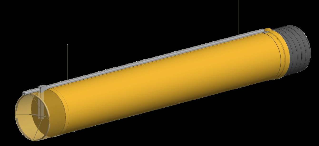
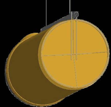
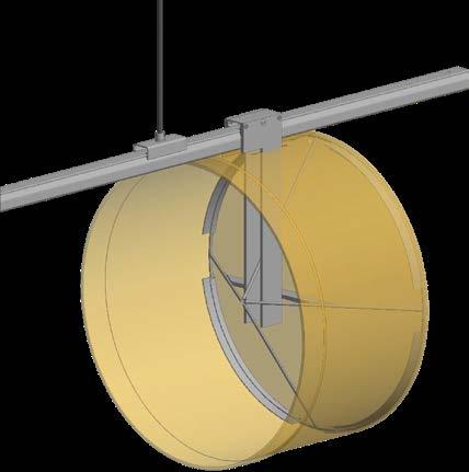
A Safebracket is fed vertically into the textile duct and into the cross brace which is fitted to the included SafeStretch® bottom ring. Then the Safebracket is clicked onto the Safetrack rail and the duct can be stretched (typically 3-5 cm) until the duct is taut and without wrinkles. The desired position of the Safebracket is held in place by fastening the screw against the Safetrack rail.
The system is easily taken down for washing etc. without the use of special tools.
Typical layouts.
KE Fibertec’s philosophy is to begin with our customer’s actual requirement and from there devise a technical solution with the purpose of creating the perfect indoor climate. This is why we call it: Design The Way You Want. The important aspect of all our solutions is that the relevant room conditions are compared with an ideal solution model so that the layout selected for the system will ensure that the air is distributed as it is supposed to be, without any problems with draughts, pulsations or noise.
Round ducts.

A textile based ventilation system comprising round ducts can be assembled from many types of bends, elbows, fittings and offsets. What all the components have in common is that they are joined together using a zipper, providing a smart, practical solution.
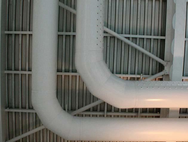
The figures and pictures show different components which can be assembled to produce the final layout. Any angle can be selected for elbows and bends, and conical transitions and T-pieces can be produced in different designs.
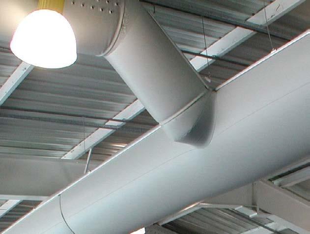
Examples of system layouts using round ducts
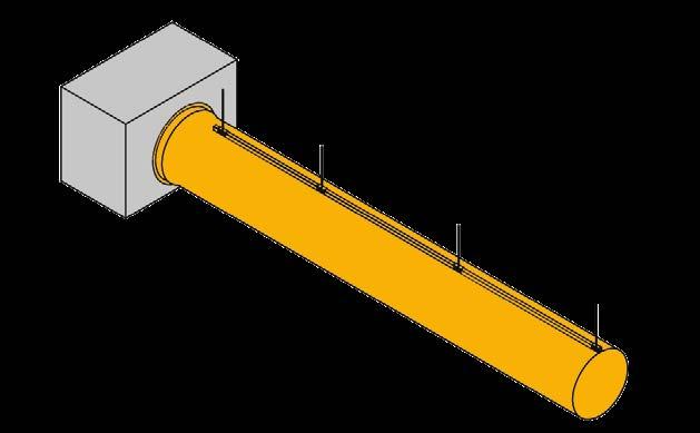
Half round (D) and quarter round (½D) ducts.

D-shaped and ½D-shaped KE-Interior Systems have been specially developed for comfort ventilation, which is why there are often major requirements in terms of their finish.
As a result, KE Fibertec puts great emphasis on the fact that these systems are highly flexible and can be produced using countless layouts. A KE-Interior System based on these ducts can, just like round ducts, be created using many types of bends, fittings and offsets, which are joined together using a zipper, providing a smart, practical solution.
KE Fibertec offers a variety of air inlet options for KE-Interior Systems, specifically round inlet sockets, an inlet socket through the top, a D-shaped inlet socket and a rectangular inlet socket can be used as part of the installation.
In the case of false ceilings, it is recommended that the air inlet pass through the roof so that all the spiro ducting can be hidden. The top of the ducts (the roof) is made of a textile material which will allow a little part of the air through. This will also prevent any formation of mould between the duct and ceiling.
D-shaped ducts can also be produced as curved ducts which are easy to include as an elegant architectural element in office buildings, canteens etc.
Examples of system layouts using half round and quarter round ducts
Indoor Climate and Acoustics.
A good indoor environment with proper acoustics is key for the well-being and concentration of the employees. A well-dimensioned ventilation system must therefore be silent. Textile ducts have a positive impact on room attenuation as they act as sound baffles in the ceiling.

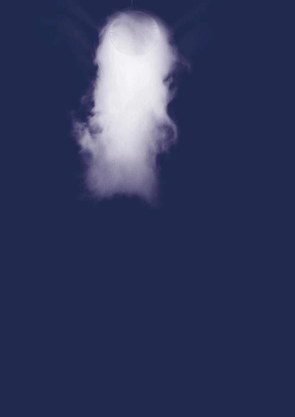
Room categories.
One of the key parameters during the design phase is determining the comfort requirements. A thorough needs analysis provides the basis for the design and a great deal of money can be saved by finding out what the end client’s actual requirements are. Unfortunately, there are far too many examples where the quality of the solution delivered does not at all reflect the end user’s expectations.
A
To simplify the whole needs analysis process, KE Fibertec has developed KE-Room Categories, which compares the four key thermal indoor climate parameters when dimensioning textile based ventilation systems. The KE-Room Categories is a tool developed on the basis of Professor Fanger’s comfort theories.
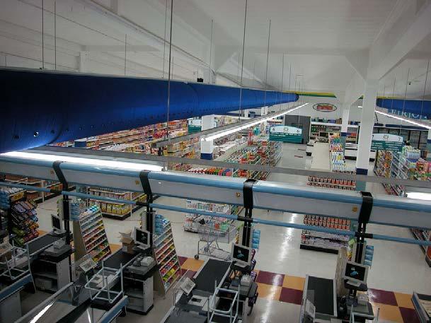
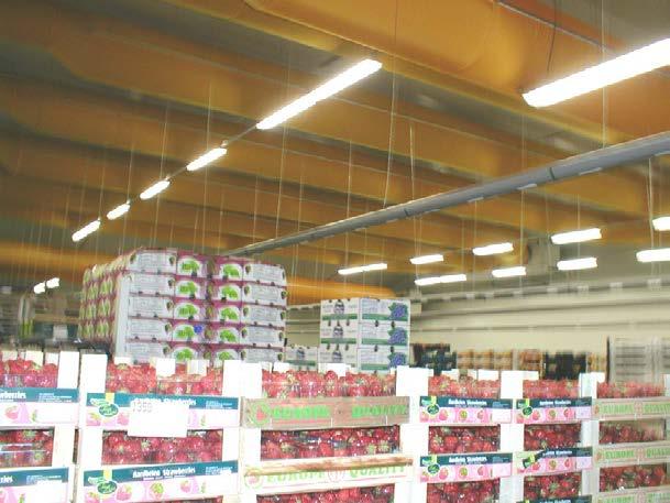
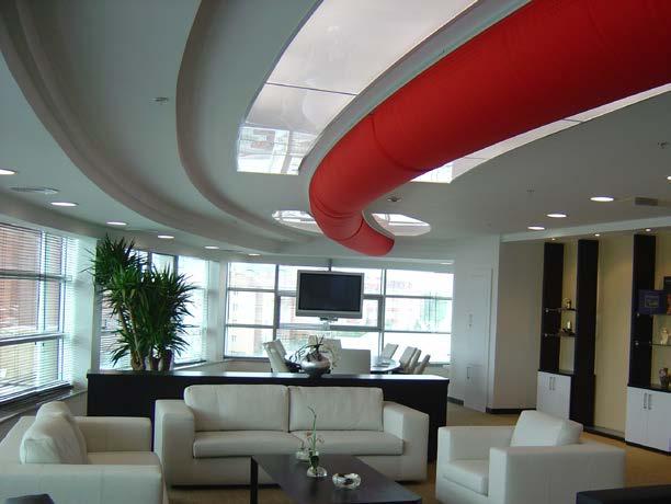
Low impulse systems (horisontal)
A B C D
Recomm. ΔT (room - inlet) Max. ΔT (room - inlet) [°C] [°C] 2.5-3.0 6.0 3.0-5.0 7.5 4.0-6.0 9.0 5.0-15.0
Velocity through textile surface: - KE-Low Impulse System - KE-Interior System [m/s] [m/s] < 0.07 < 0.09 < 0.09 < 0.11 < 0.15 < 0.18
Temperature difference: - Occupied zone - Near zone Uniform 85-90 % mixing Slight difference 65-75 % mixing Major difference 60-70% mixing Variable Max. variation in supply temperature [°C] ± 0.5 ± 1.0 ± 1.5
Max. cooling load per running metre of textile duct at nom. ΔT(1)
Max. cooling load per running metre of textile duct at max. ΔT(1)
[W/m] [W/m]
260 95
700 175
1500 200
5,000
Max. cooling load per m2 of floor area [W/m²] 100-130 175-200 250-300 Recommended max. centre distance between ducts [m] 2-4 4-8 5-10 5-10
(1) Installation height: 4 m up to the bottom edge of the duct. See datasheet 1 for other installation heights.
High impulse systems / Hybrid systems
A B C D
Recomm. ΔT - KE-Inject: Cooling (room - inlet) Heating (inlet - room) [°C] [°C] 4.0-6.0 3.0-5.0 6,0-8.0 4.0-6.0 8.0-10.0 5.0-7.0 10.0-15.0 8.0-12.0
Recomm. ΔT - KE-DireJet: Cooling (room - inlet) Heating (inlet - room) [°C] [°C] 4.0-6.0 3.0-6.0 6,0-10.0 4.0-8.0 8.0-12.0 6.0-10.0 10.0-15.0 8.0-15.0
Recomm. min./max. room height
KE-Inject System [m] 3-4 4-6 4-6
Throw length (ST-2)(2)
- KE-Inject LV
- KE-Inject MV - KE-Inject JET
Recomm. min./max. room height
[m] [m] [m]
1.8 2.6 6.4
1.4 1.6 3.4
1.1 1.2 2.1
KE-DireJet System - Ø12, Ø18, Ø24 mm - Ø48, Ø60 mm [m] [m] 5-9 9-14 6-10 10-16 7-11 11-25
Throw length (ST-2)(2)
- KE-DireJet Ø12 mm
- KE-DireJet Ø18 mm
- KE-DireJet Ø24 mm
- KE-DireJet Ø48 mm
- KE-DireJet Ø60 mm
[m] [m] [m] [m] [m]
5.6 8.3 13.1 23.6 26.1
4.3 6.3 9.9 17.8 19.7
3.5 5.1 8.0 14.3 15.8
(2) Throw length calculated for one row of holes and one nozzle respectively at 100 Pa static pressure. See datasheets 12-20 for further information.
Note: The tables are only intended as a guide. Please contact KE Fibertec for further information.
Sound calculations.
Noise is the name used in everyday parlance for unwanted sound, i.e. sounds that irritate, disturb or harm people. A well-dimensioned ventilation system must therefore make little noise. KE Fibertec considers it important to be able to document how much noise our TBV systems make. In this section a brief description of the theory behind the sound calculations is given.
Where does noise come from?
In a ventilation system the sources are noise from the actual installations, as well as noise generated by the air’s movement. Noise generated by the installations originates mainly from the air conditioning system where fans generate noise. By the very nature of this phenomenon, KE Fibertec cannot say how much noise is transmitted by the air conditioning system. It is simply important to point out that this noise needs to be attenuated before it reaches the TBV system as textile ducting cannot attenuate fan noise.
KE Fibertec’s documentation applies to noise generated by the air’s movements, i.e. noise created by the pressure drop/fluctuations which arise in the textile duct. In low impulse systems the inlet velocity is often the critical factor. In the case of KE Fibertec’s high impulse systems, the outlet velocity through the holes or nozzles is often the critical factor.
Sound power and sound pressure.
The sound power P is a direct measurement indicating how much sound power a sound source is trans-mitting. The sound power is therefore directly linked to the sound source and is measured in watts (W). The sound pressure p is a measurement of the sound’s strength at a given distance from the source. It is characterised by the pressure vibrations which an ear picks up or is measured using a sound meter. Sound pressure expresses how the listener perceives the sound and largely depends on the location of the sound source and the room’s acoustic properties. Sound pressure is measured in Pascals (Pa).
What is sound?
Sound is the vibration of air molecules in the atmosphere that can be sensed by the ear. As the air molecules are set in motion, they radiate outwards, colliding into other air molecules until they strike the ear drum.
Sound power level and sound pressure level.
Given that the human ear’s perception of sound is almost logarithmic, a logarithmic scale has been introduced to specify sound in the audible frequency range. As a result, when it comes to performing acoustic calculations, the concepts sound power levels, Lw, and sound pressure levels, Lp are used.
The sound power level Lw is linked to the sound source and is independent of the room’s acoustics. The sound power level is expressed in decibels (dB). The sound pressure level Lp is directly dependent on the sound power level and expresses how the listener perceives the sound. It largely depends on the location of the sound source and the room’s acoustic properties. The sound pressure level is expressed in decibels (dB).
Room attenuation.
Room attenuation specifies the difference between the sound power level transmitted and the sound pressure level exerted in the room. This means that the sound pressure level is obtained by subtracting the room attenuation (RA) from the sound power level generated by the source.
The relation between the sound power P and the sound power level LW is described by the following expression:
LW = 10 x log (P/Pre) Where: P Actual sound power transmitted [W] P re Reference sound power (10-12 W)
The relation between the sound pressure p and the sound pressure level Lp is described by the following expression:
L p = 20 x log (p/pre) Where: p Actual sound pressure [Pa] pre Reference sound pressure (20 mPa)
Room attenuation specifies the difference between the sound power level transmitted and the sound pressure level exerted in the room.
RA = L w - L p Where: RA Room attenuation [dB]
What
influences the noise in the room?
Unlike the sound pressure level, the sound power level is a product-specific value. As a result, the TBV system’s acoustic features are specified at a particular sound power level. If the sound pressure level also needs to be used, the room attenuation has to be estimated. Room attenuation is, as stated on the opposite page, an expression of the difference between the sound power level transmitted and the sound pressure level exerted in the room. Room attenuation is, by its nature, very complicated to calculate properly as it depends, e.g.:
• Geometry and dimensions of the room
• The room’s surface characteristics
• Location of the textile ducts
• Number of textile ducts
• Distance from the source to the recipient
When a sound is emitted from a sound source, it is received in the room as either direct sound or reflected sound. The further away the location of the source, the less the direct sound will contribute to the overall sound pressure level perceived by the ear. The reflected sound will be of the same magnitude throughout the whole room and depends on the room’s soundproof properties, which can be described as an equivalent absorption area (A). The absorption area is specified in the unit m2 Sabine.
The most reliable method for determining the room attenuation is to take measurements of the reverberation time in the relevant room. However, as it is rarely possible to do this during the design phase the room attenuation can be estimated by using diagrams. These diagrams are shown in datasheet 25. Diagram 1 operates by using the relevant room’s volume as an input parameter for finding the equivalent sound absorption area (A). The distance from the textile duct (r) is then used, along with the directivity coefficient (D) to determine the room attenuation (RA). The directivity coefficient can be estimated based on the table to the right.
As shown in the table to the right, the directivity coefficient for D-shaped ducts fitted in the ceiling will always be 2 or 4, depending on whether the duct hangs in the middle of the room or along a wall.
What is noise?
Noise is undesirable sound that causes damage or is troublesome. We each experience noise in different ways.
What is sound power level?
The sound power level, Lw, is measured in dB and and is the acoustic energy emitted by the sound source. It is not affected by the surroundings.
Sound power level (L )
Sound pressure level (L ) w p
What is sound pressure level?
The sound pressure level, Lp, is measured in dB and quantifies the magnitude of sound. The sound pressure level is influenced not only by the power of the source but also by the surroundings and the distance from the source to the recipient.
What is decibel?
Decibel (dB) is a logarithmic unit used for expressing the ratio of two powers. The most common use is in measuring sound power level and sound pressure level.
Because of their soft surface, textile ducts always have a positive impact on room attenuation as they act as a kind of sound absorber in the ceiling, absorbing and breaking up part of the sound reflected in the ventilated room.
Walkden High School’s new building was constructed as part of BSF, Building Schools for the Future. To ensure that the class rooms would not receive any unnecessary noise from the ventilation ducts the consulting engineers requested a noise test in order to establish how much noise is absorbed by textile ducts.
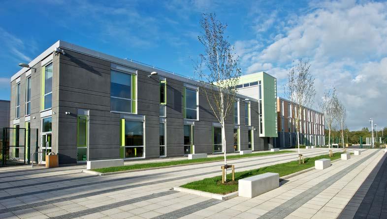
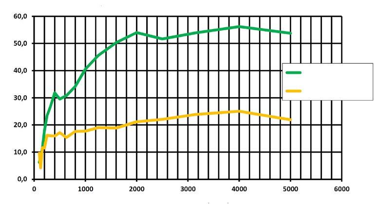
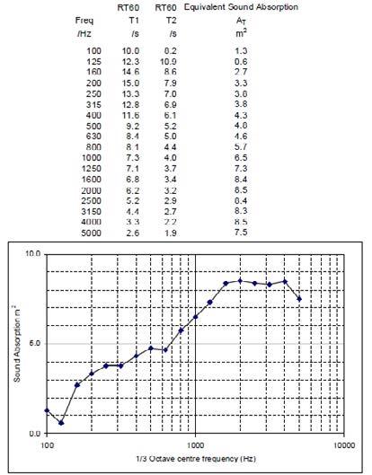
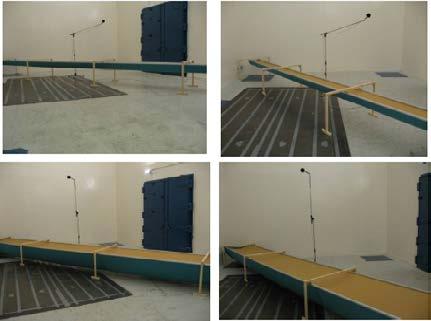
The test was performed by the University of Southampton for the purpose of establishing the room attenuation effect through textile ducts. KE Fibertec’s R&D department has carried out their own “equivalent absorption” calculation based on the results from the testing done at the University of Southampton.
Sound Absorption
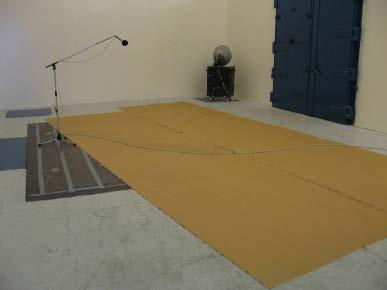
When a sound wave disseminates in the air and hits a material, e.g., a wall, a portion of this energy is reflected. Some will be transmitted through the wall and some will be absorbed by the wall and transformed into heat energy.
Read the case at ke-fibertec.com
Sound requirements.
There is often a requirement for a maximum noise level in an occupied zone. This requirement depends on how the room is used and how regularly. It is often specified as an LpA value or an NR value.
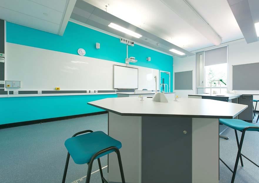

The LpA value specifies the A-weighted sound pressure level which is standardised using an A-filter. The A-filter makes an adjustment for the human ear’s different perception of the sound, with the high tones being assigned the most weight. All KE Fibertec’s sound data is adjusted using the A-filter, see the table below: 63
A-Filter
Originally LpA values would be applied up to 55 dB, LpB values would be applied within the range of 55-85 dB, and the LpC values would be applied above 85 dB, however, most often it is the A value range that is applied.
In the specific standards for mechanical ventilation systems, recommended design values most often are specified for the maximum A-weighted sound pressure level in different premises. NR is short for Noise Rating. NR curves are approximately weighted to the human ears perception of sound and are standardised in accordance with the International Organization for Standardization (ISO). As a general rule of thumb, the following expression can be used for NR:
NR = LpA - 5
Sound measurements.
All KE Fibertec’s sound data is based on relevant noise measurements. We have collaborated with the acoustic laboratory Peutz & Associes B.V. in the Netherlands and HN AKUSTIK AB in Sweden to carry out a noise test on our textile based ventilation systems.
The noise measurements have been taken in accordance with the requirements in ISO 3741 (Acoustics – Determination of sound power levels of noise sources using sound pressure – Precision methods for reverberation rooms) and ISO 5135 (Acoustics – Determination of sound power levels of noise from air-terminal devices, air terminal units, dampers and valves by measurement in a reverberation room).
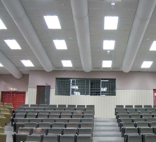
Forest
Threshold of hearing
Whispering
System design.
The sound power level generated by low impulse systems is dependent, to some extent, on the inlet’s location and, to a large extent, on the air’s inlet velocity. In the case of KE Fibertec’s high impulse systems, the generated sound power level is particularly dependent on the outlet velocity through the holes/nozzles, as well as on how many holes/nozzles per running metre of ducting are used.
Conversation Heavy truck
Average factory noise
Rock concert
There are innumerable possible ways of combining KE Fibertec’s textile based ventilation systems. For this reason, it is obviously not possible to carry out a noise test for every combination. Instead of this, a basic sound power level is used for the specific duct. This sound power level must be corrected later on so as to match the relevant layout.
The basic sound power level can be taken from datasheet 21 once the total pressure loss for the textile based system is known. It should be noted that this is the overall pressure loss for the textile ducts only.
After this, the basic sound power level must be corrected for the relevant layout of the system. This is done by using the duct length and the relevant number of hole rows, r, or the total number of nozzles and the duct length as an input parameter in datasheets 22, 23 and 24 where the correction value in dB is taken from.
The correction value must be added or subtracted from the basic sound power level. It is recommended allowing KE Fibertec to perform the final noise calculation for the specific installation. The noise calculation is performed automatically in our 3D dimensioning program TBV Designer, in the same way as for the pressure losses, air velocities etc.
Sample calculation.
We will start with the value for a KE-Low Impulse System calculated under Design process. It is assumed that room attenuation can be calculated based on a normally attenuated room.
Maximum sound pressure level in room: 25 dB (A) Input parameters from datasheet 21: Pt = 118 Pa Basic sound power level: = 28 dB(A)
Correction for duct length: Input parameters from datasheet 24: L = 9 m Correction (approx.): + 3 dB(A) Resulting sound power level per duct: 28 dB(A) + 3 dB(A) = 31 dB(A)

Resulting sound power level transmitted to room: 31 dB(A)+3 dB(A)+2 dB(A) = 36 dB(A)*
Input parameters from datasheet 25 top: Room volume = 825 m3, normal room Result: Equivalent sound absorption area = 90 m2 Sabine
Input parameters from datasheet 25 bottom: r = (4.8 m - 1.8 m) = 3 m D = 2 (placed on the ceiling) r / D = 3 / 2 = 2.1
Value taken for room attenuation: RA = 12 dB(A)
Resulting sound pressure level in room: 36 dB(A) - 12 dB(A) = 24 dB(A) < 25 dB(A)
*A logarithmic addition of the sound power levels is performed.
Jet engine
Threshold of pain
TBV Design and Visualisation.
As the only manufacturer in the world we offer customised woven textiles from our own weaving mill. Our materials are designed for air distribution - not for tents or patio blinds when it comes to uniform air distribution, shrinkage after washing, colour-fastness, and not least best possible Dust Holding Capacity. We offer a wide range of duct colours and layouts - that is freedom of design.

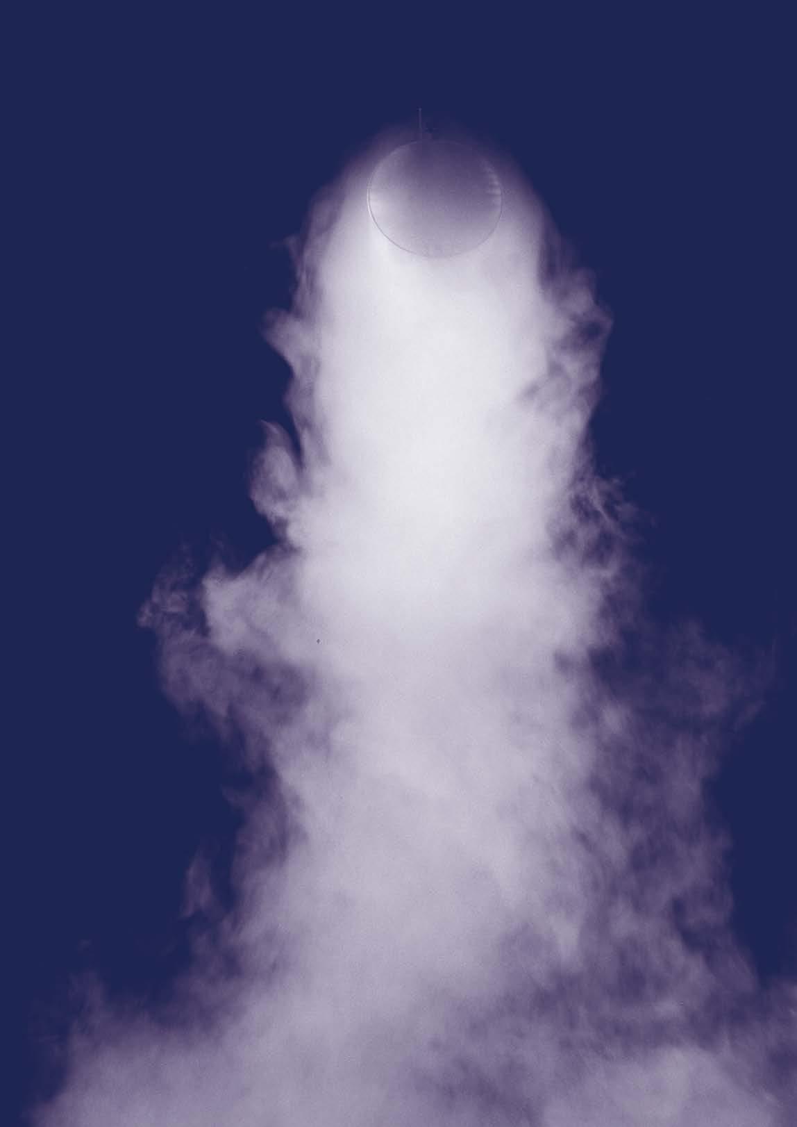
TBV Designer.
Flexibility and customised solutions are what characterise KE Fibertec’s TBV solutions. Here you get design freedom and great flexibility of your own choice when designing the textile duct, so that the solution fits into the building’s architecture, both in terms of system layout, colours, materials and whether the air distribution should be passive, hybrid or fully active.
We offer a wide range of standard colours, but at an additional cost we can also offer dyeing the fabric in a specific colour in order to tailor the duct design to the interior.
Providing 3D design.


For the dimensioning of our textile duct solutions we use the 3D TBV Designer – a-state-of-the-art tool. We customise your solution with the required flow rate and the space dimensions by using the TBV Designer to design a system tailored to meet the ventilation requirements of the room.
State-of-the-art design. With many years of experience and a high level of technical knowledge in textile based ventilation we have developed the TBV Designer programme from scratch and continuously developed and improved it so that it is always based on the latest technology.
The programme allows you to visualise the solution and provides you with data such as thermal air velocities in the occupied zone, pressure loss, sound data, and calculation of carbon footprint.
Information available in TBV Designer
Thermal air velocities in occopied zone
System pressure loss
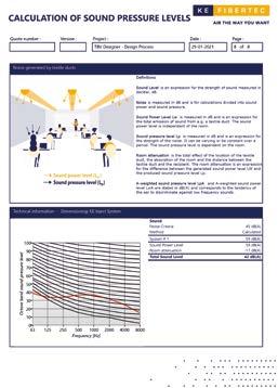
Pressure loss in substrings
Sound data
Calculation of carbon footprint
Thermal penetration
Revit plugin.


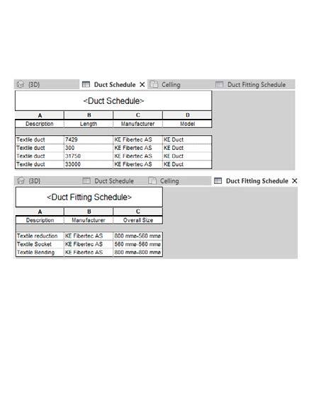
Many consulting engineers and installers use Revit to design ventilation solutions. KE Fibertec has developed a plugin for Revit and can offer a wide range of duct systems as BIM components to suit all your project building applications enabling you to send the design directly from the user to and from KE Fibertec.


If you need any assistance, please view the user guide at www.ke-fibertec.com that will outline the step-by-step process. The plugin comes with KE families which are automatically loaded into Revit. These families contain round textile ducts as well as FBS Panels.
These families provide flexibility to the design of a textile based ventilation solution that does not collide with other elements of the building. However, technology is not an integral part, so pressure loss and velocities are not calculated, but can be stated by KE Fibertec or read in data sheets 8-11 and 16-17.
When project quotations are loaded via this plugin, it is possible to see the associated description, technical data and quotation number of KE Fibertec.
The round duct family contains:
Straight duct
Elbow
Bend
Conical transition round to round
Conical transition square to round
Inlet
Unique colours and materials.
CRADLE TO CRADLE MATERIALS / COLOURS PANTONE / RAL
GreenWeave.
Energy-efficient and sustainable textile duct material.
GreenWeave is especially suited for comfort installations with high demands on indoor air quality. Typical applications are offices, schools, laboratories, conference centres, and cold work rooms in food industry.
WHITE 11-0601-TP / 9010
TM
BLACK 19-5708-TP / 9005
LIGHT GREY 12-4705-TP / 9002
DARK GREY 17-4402-TPG / 7042
TM TM TM
MultiWeave.
Durable and versatile textile duct material.
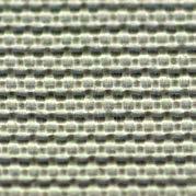
MultiWeave is a multifunctional material that is highly suited for many different applications, from cleanroom facilities of ISO class 4, industrial facilities and sports halls to equalising rooms in meat factories.
DARK BLUE 19-3864-TP / 5002
YELLOW 14-0955-TP / 1028
RED 18-1655-TP / 3031
TM TM TM
• Filters the supply air as an M6 prefilter acc. to EN779:2012
• Longer washing intervals with staple fibre yarns

WHITE 11-0601-TP / 9010
ANTISTATIC
• Dust holding capacity of 25 g/m² textile surface acc. to EN779:2012
• Fire tested acc. to EN13501 B-S1-d0
• 100% recyclable and Cradle-to-Cradle certified material
• GW materials are yarn dyed, which saves approx. 2/3 of the wastewater consumption compared to conventional piece dyed materials
WOVEN COLOURS - PANTONE/RAL
WHITE 11-0601- TP / 9010
LIGHT GREY 12-4705-TP / 9002
STOCK COLOURS - PANTONE/RAL
YELLOW 14-0955-TP / 1028
RED 18-1655-TP / 3031
DARK BLUE 19-3864-TP / 5002
LIGHT BLUE 16-4132-TP / N/A
BLACK 19-5708-TP / 9005
GREEN 18-6024-TP / 6016
BEIGE/TAN 15-1215-TP / 1019
DARK GREY 17-4402-TPG / 7042
• Material made of multi-filament yarn that works as a G2 prefilter
• Cleanroom certified as class 4 acc. to ISO 14644-1
• Fire tested acc. to EN13501
• Highly durable material. Tear strength 110 - 210 N (EN ISO 13937:2)
Nomex.
High-temperature resistant aromatic polyamide fibres.
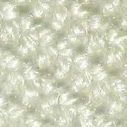
The Nomex material of KE Fibertec is woven in a twill weave using staple fibres to ensure largest possible textile surface and uniform air permeability.
WOVEN COLOURS - PANTONE/RAL
NATURAL 11-0701-TP / N/A
MIDNIGHT BLUE 19-4023-TP / N/A
• Flame-resistant properties - it will neither melt, drip, nor combust in air
• Fire tested acc. to EN13501 B-S1-d0
• Used for applications where materials are required to be able to withstand intense heat
• Shrinkage- and permeability-stabilised material
AVAILABLE COLOURS - PANTONE/RAL
ZeroWeave.
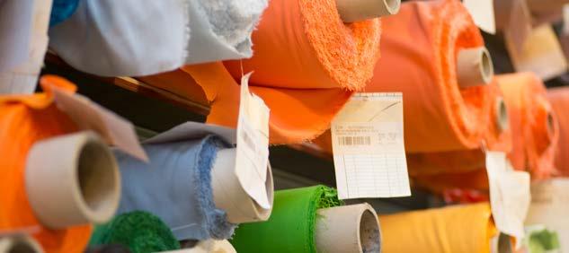
Airtight textile duct material. Low-maintenance material with a wide range of application possibilities such as supermarkets, large sports arenas, swimming pools, high-bay industrial facilities, and rooms with high dust generation or limited accessibility.
WHITE 11-0601-TP / 9010
LIGHT GREY 14-4201-TP / 7047
DARK BLUE 19-3864-TP / 5002
• Airtight material with zero filter efficiency
• No PVC, halogens or other harmful substances
• Fire tested acc. to EN13501 B-S1-d0 without any finishing treatment
• No condensation issues when used in environments below 90% RH
Custom colours. KE Fibertec can supply TBV systems in up to 1600 custom colours. Contact KE Fibertec’s sales department for further information.
Dimensioning TBV systems.
To be able to dimension a textile based ventilation system, it is important to understand a number of essential parameters and concepts. A textile based ventilation system is not fundamentally different from conventional ventilation systems, but there are
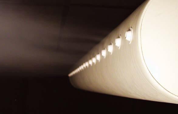
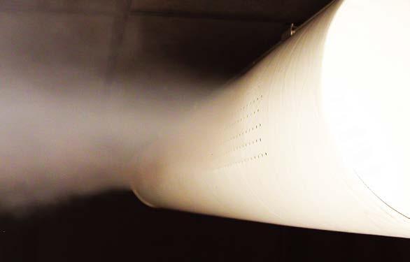
a number of key points where it is important to be extra cautious. A brief description is given below of the key parameters and concepts used when dimensioning KE Fibertec’s textile based ventilation systems.
Delivery areas
The entire surface of the KE-Low Impulse System is permeable, which means that the total delivery area corresponds to the geometric surface area. The geometric surface area, A, is given in [m2].

KE-Low Impulse System: A = diameter · π · duct length
KE-Interior System (D): A = (1/2) · diameter · π · duct length
KE-Interior System (½D): A = (1/4) · diameter · π · duct length
In the case of the KE-Inject System and the KE-Inject Hybrid System, KE Fibertec has, for the sake of manufacturability, grouped the holes in different standard patterns, depending on which type is selected, see page 46.
A standard pattern is made up of an exact number of hole steps and the delivery area can only be modified by changing the number of hole rows. Consequently, the unit, number of hole rows, is used as a parameter for the delivery area of the KE-Inject System. In the case of the KE-Inject Hybrid System, the whole of the duct’s surface, including the holes, will act as the delivery area.
In the case of the KE-DireJet System and KE-DireJet Hybrid System, the delivery area depends on whether a Ø12 mm, Ø18 mm, Ø24 mm, Ø48, or Ø60 mm nozzle is selected, as well as how many nozzles are used per running meter of ducting. With the KE-DireJet Hybrid System, the entire duct surface, including the nozzles, will act as the delivery area.
Pressure conditions in textile ducts.
As in any other air distribution system, pressure losses also occur in textile based ventilation systems. Calculating the pressure losses in a textile based ventilation system is not basically any different from the generally known practice.
The flow in a duct system is only dependent, to a limited extent, on whether the material is made of steel or fabric.
However, what is important to be clear about is that textile material is very flexible and it is only kept inflated by the static pressure in the system. As a result, even small turbulences can cause pulsations. This is why it is very important to perform pressure loss calculations to ensure that the textile based ventilation system is operating as it is supposed to without any pulsations, as well as ensuring the best possible energy economy.
Definitions of pressure
The types of pressure that occur in a textile based ventilation system are shown in the figure on the right.The total pressure (Pt) can be calculated anywhere in a textile based ventilation system as the sum of the static and dynamic pressures. The following expression applies:
P t = P s + Pd
Where:
P t Total pressure in the duct [Pa]
P s Static pressure in the duct [Pa]
Pd Dynamic pressure in the duct [Pa]
Total pressure
The total pressure is the pressure that needs to be produced by the fan to overcome the total resistance in the textile based ventilation system, i.e. the loss from the individual types of resistance, such as elbows, frictional loss and the static pressure in the system.
Static pressure
The static pressure, which is measured in relation to atmospheric pressure, has an identical impact in every direction and keeps the textile material inflated, as well as pushing the air out through the holes/nozzles.
Dynamic pressure
The dynamic pressure, or velocity pressure, has an impact on the direction of the air and carries it from A to B. The dynamic pressure is related to the mean air velocity in the duct and is calculated using the following expression:
Pd = ½ · r · v2
Where:
r Density of the air [kg/m3]
v Mean air velocity in the duct cross section [m/s]
Ps Pt
Pd Flow Pt Flow Pt Ps
Ps Flow
Pressure loss in textile ducts.
The pressure loss which occurs in a textile based ventilation system originates from the following sources:
• Across cross section modifications
• Across branches
• Across elbows
• Friction
• Across flow components (SRD’s)
• Across holes, nozzles and textile material (“fittings
The pressure loss across these various components is a loss that is related to the velocity, and thus is proportional to the dynamic pressure, Pd, and dependent on what is known as the pressure loss coefficient, which is found when measurements are taken in KE Fibertec’s full-scale laboratory. The pressure loss across a component (DPe ) is determined using:
It is very obvious when a textile based ventilation system has been dimensioned incorrectly because the ducts will be oval and “sagging” when you look at them.
The difference in the static pressure between two parallel ducts may be quite considerable too. This not only has an impact on the aesthetic appearance, but to a great extent also on air distribution.
If the pressure distribution is uneven this can cause draught problems below and around the duct with the highest static pressure, while in the opposite case, the air quality will be poor in the area where the static pressure (and therefore the volume of air) is not sufficient.
KE Fibertec AS has documented pressure loss measurements for all the components featuring in our TBV systems. Contact KE Fibertec’s development department for further information.
Where:
x Pressure loss coefficient [-]
Pd2 Dynamic pressure after the component [Pa]
Pulsations in textile ducts.


Pulsations in textile ducts can most often be attributed to one or more of the following causes:
If a system has an turbulent air flow in front of the textile duct‘s inlet this can create a turbulence field in the duct causing pulsations in the textile material. One of the reasons for the turbulent air flow may be changes of direction in front of the textile duct.
It is therefore recommended to have a length at least three times the actual diameter in front of the textile duct where the flow profile has been restored. In addition to this, if the air velocity is too high in elbows and attachments, this can also pose the risk of pulsations in the textile material. The risk arises because low pressure may be generated locally in the textile based ventilation system due to return flow
Textile ducts where the air is delivered from the side or from above, such as D-shaped ducts with an inlet in the roof, are at risk from pulsations. These types of systems are obviously designed with a low inlet velocity, but if

This is often observed inside an elbow where the low pressure will create a wave motion in the textiles surface.
In cross sections with turbulent air flow it may be beneficial to use a KE-SRD (Static Regain Diffuser), which regenerates the flow profile. This is done by forcing the air through a conical mesh so that the air flows perpendicularly on the side of the duct. This then converts the dynamic pressure wave in the duct to a static pressure, thereby preventing pulsations in the relevant cross section. This will obviously cause an additional pressure loss in the system as the static pressure in front of the SRD is raised. The fan must also overcome this pressure loss.
the ventilation system’s parameters are not set properly this can easily generate pulsating movements at the inlet. The problem can be resolved by using a KE-SRD.


Textile ducts which are fitted onto sockets at the end of a rectangular steel duct, for instance, are at significant risk of pulsations as the supply air will become very turbulent when it hits the bottom of the steel duct. In these cases, pulsations can be avoided by fitting baffle plates in the steel duct (Solution 1), inserting a KESRD (Solution 2) or by extending the steel socket to at least 3 x D. A defective design also creates the risk of pulsations in the textile material. A defective design is often associated with the static pressure in the textile based system not being sufficiently large to compensate
for the pressure loss in the sockets and elbows, with excessively high inlet velocities, an asymmetrical system layout or the wrong textile permeability.
To prevent pulsations, KE Fibertec recommends using a pulsation factor to ensure that there is sufficient static pressure available in the system. According to the pulsation factor, the static pressure in the outlet ducts must be greater than or equal to the sum of the dynamic pressure in the outlet duct and the total system pressure loss in the textile based ventilation system.
Pressure impact on system start-up.
It is recommended that ventilation systems with textile ducting use a soft-starter, frequency converter or a control damper to ensure that the system starts up slowly. If this is not done the following sequence of events will occur:
A - A A A A - A A A A - A A A A - A A 1 2 3 4
TBV DESIGN AND VISUALISATION / PRESSURE 94
Round textile ducts hang straight down when the ventilation system is not in operation, with the ducts hanging down slightly compared to when the system is on. The ducts contain absolutely no air.
In simple systems controlled using an ON/OFF mechanism the fan will reach full capacity very quickly after start-up. As the duct is still hanging down loosely, the duct’s cross-sectional area will be very restricted and the air velocity in the duct will therefore become very high. As no static pressure has yet built up in the duct, the horisontal air movement will generate a powerful wave motion travelling forward through the textile duct.
When the powerful horisontal air movement reaches the bottom of the textile duct, it will arrive with such force that it may cause the suspension system and textile duct to come loose with the vibration or even sustain serious damage. When the horisontal movement has reached the bottom of the duct, the static pressure in the duct will start to be exerted on the duct’s sides and the duct will be inflated from the end back towards the fan. This generates a powerful wave motion travelling backwards through the textile duct.
P s/Pd ratio.
As a result of their permeable surface, the volume of air and air velocity in textile ducts, unlike in ordinary steel ducts, continually decreases along the duct. This means that the dynamic pressure falls along the duct, while the static pressure rises. This results in a large portion of the air being delivered at the end of the duct where the dynamic pressure is zero.
As the volume of air continually decreases along the duct friction loss may often be ignored. This means that the total pressure and static pressure will be more or less identical at the bottom of the duct.
Flow Pt Pd Ps
One solution frequently used to ensure that air is distributed uniformly through very long ducts is to restore the dynamic pressure in the system by inserting a duct reduction, in the middle of the duct, for instance.
This will break the static pressure in the duct, thereby achieving a more even distribution of air. This is also the most economical solution if duct reductions are acceptable. To facilitate installation, single suspended ducts should have duct reductions with flat edge on top, while double suspended ducts should have centred duct reductions.
In order to produce a uniform distribution of air along the entire system’s longitudinal direction, the static pressure in the middle of the textile duct should always be at least double that of the dynamic pressure in the duct’s inlet.
120 110 100 90 80
[Pa] 0 25 50 100 75 [%]
Flow Pt Pd Ps
120 110 100 90 80
Pt Pd Ps
5.0 4.0 3.0 2.0 1.0 Length of duct [m] 0102030405060708090 100 0 PRESSURE / TBV DESIGN AND VISUALISATION 95
[Pa] 0 25 50 100 75 [%]
P P [-] s d
Entrainment in textile ducts
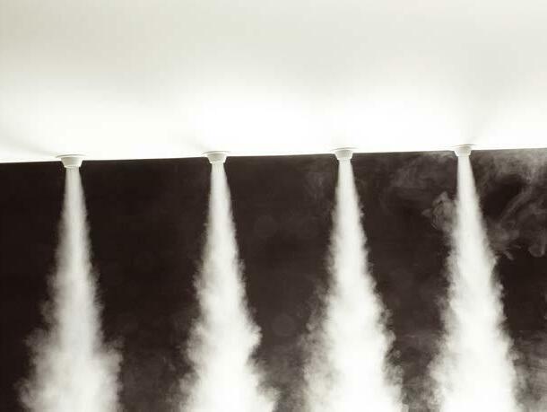
It is well known in flow engineering that holes positioned with a perpendicular direction in a long main duct can cause problems. The main problem is that the air has a tendency to veer away and flow parallel to the main duct, unless the holes or nozzles are fitted with baffle plates.
In the vast majority of cases, entrainment will cause problems with air distribution in the premises. At one end of the room (nearest the inlet), problems may arise with stagnant air, while at the other end of the room, entrainment may be the cause of major draught problems. Entrainment occurs if the inlet velocity is significantly higher than the outlet velocity through the holes in the textile material. To counter this inconvenient deflection of flow (entrainment), KE Fibertec recommends that the outlet velocity through the holes be at least 35% higher than the inlet velocity in the duct.
Another factor which has an impact on entrainment is the size of the hole that has been cut out. If air is supplied through large holes it will always have a tendency to deviate and flow along the duct.
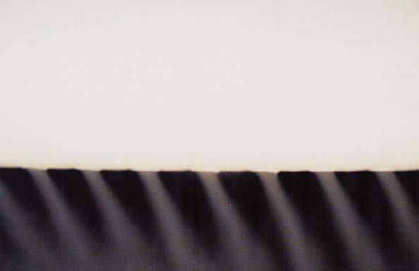
The KE-DireJet System never has problems with entrainment. The nozzles are designed with a length that ensures the air is discharged perpendicularly to the main duct. In the KE-Inject System the holes are cut directly in the textile, which means that the use of baffle plates is not an option. On the other hand, entrainment does not occur to such a noticeable extent in this case either. The reason for this is because the air velocity at the centre of the hole, i.e. perpendicular to the main duct, is usually higher in the KE-Inject System than in conventional systems.
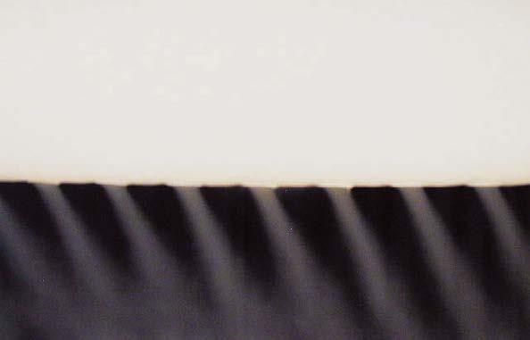
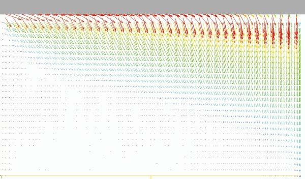
Permeability.
Air permeability through the textile material’s surface is crucial to how great the static pressure will be for a given volume flow. The tighter the material’s weave, the higher the pressure will be as a function of volume flow.
For all KE Fibertec’s low impulse materials, the static pressure increase is given as a function of volume flow per m2 of the textile material’s surface. Permeability is expressed in the unit [m³/m²/h]. See datasheets 6 and 7 for more information.
Maximum inlet velocities.
The inlet velocity is a critical design parameter for textile based ventilation systems as it has a major impact on aspects such as pulsation, noise generation, the material’s durability and the air distribution from the duct.
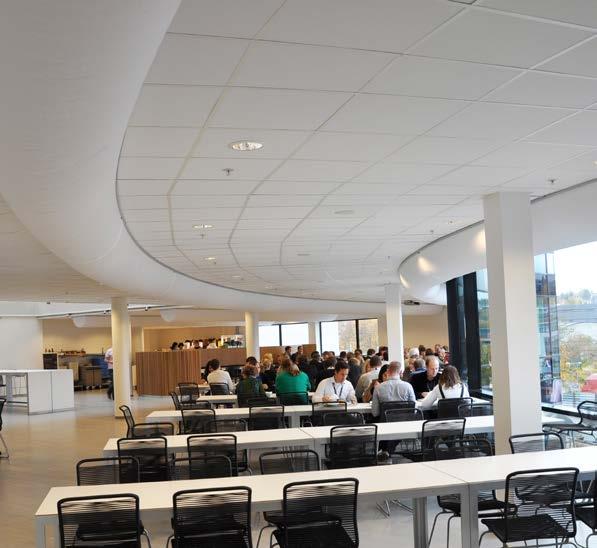
The recommended inlet velocity for round ducts is no more than 6-8 m/s, depending on the entry method. In the case of KE-Interior Systems, air velocities of between 4 and 7 m/s may be permitted, depending on the entry method.
4 m/s Max
Max
Outlet velocities - Low impulse.
The outlet velocity through textile based low impulse systems depends on the geometric surface area as the air is slowly diffused through the whole surface of the textile material.
Outlet velocities – High impulse.
The static pressure keeps the textile based ventilation system inflated, but the static pressure pushes the air out through the holes/nozzles and if necessary, through the textile material. The outlet velocity is a very significant parameter in the calculation of the throw length, thermal penetration length etc., but in reality, it is very difficult to measure.
On the other hand, any calibrated manometer can be used to measure the static pressure in the duct. With a standardised hole design and a detailed knowledge of the properties of the holes and nozzles, any given outlet velocity will always correspond to the same static pressure in the duct.
Design process - practical examples.
The examples below present quick estimated calculations for a KE-Low Impulse System, KEInject System and a KE-DireJet System. It goes without saying that KE Fibertec carries out extensive calculations for all specific installations using
Dimensioning: KE-Low impulse system
The following input data is provided:
our proprietary 3D-dimensioning program TBV Designer. We therefore recommend allowing us to perform the final calculation so that calculations for pressure drop, air velocities and sound levels are performed on the basis of detailed models.
Room dimensions (L x W x H): 15 m x 10 m x 5.5 m
Lower edge of duct: 4.8 m above floor level
Heat distribution in room Normal
Heat load in premises: 17400 W
Number of sockets and location: 3 sockets on the end wall
Inlet temperature and desired room temperature: 16°C / 20°C
Volume of air per socket: 4300 m³/h
Maximum air velocity in near zone: 0.20 m/s (room category B)
Total pressure available for textile ducts: 130 Pa
Room dimensions and layout
15 m
10 m
4.8 m 5.5 m
Calculation process
The following calculation process is used:
1. Determine the maximum cooling load per metre of ducting 2. Determine the required duct length 3. Determine the number of low impulse ducts 4. Determine the duct diameter 5. Determine the type of textile material 6. Check the air velocity at the entrance to the occupied zone 7. Calculate the pressure loss 8. Calculate the noise level
Maximum cooling load per metre of ducting
Input parameters from datasheet 1 - diagram: DT = 4°C and room category B
Result: F m = 500 W/m
Input parameters from datasheet 1 - table: d = 3 m and normal heat distribution
Correction, k, for duct location: k = 1.31
F max = F m x k = 500 W/m x 1.31 = 655 W/m
Required duct length
17400 W / 655 W/m = 27 m
Number of low impulse ducts and system layout
27 m / 10 m = 3 ducts at L = 9 m
Duct diameter
Input parameters from datasheet 3: 4300 m³/h and max. 7-8 m/s for inlet velocity
Duct diameter: D = Ø500 mm, v = 6 m/s
Choice of textile material
Input parameters from datasheet 6:
Surface area per duct: p x D x L = p x 0.5 m x 9 m = 14.1 m²
Permeability: 4300 m³/h / 14.1 m² = 304 m³/h/m²
Choice of material: GW320, Ps,mid = 112 Pa
Air velocity check
Maximum cooling load per metre of ducting: F max = 655 W/m
Actual cooling load per metre of ducting:
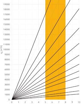
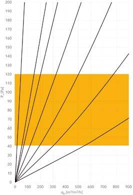
FActual = Q v x r x c p x ΔT / L
FActual = (4300 m³/h x 1/3600 s/h x 1.205 kg/m³ x 1007 J/(kg·°C) x (20°C - 16°C)) / 9 m
FActual = 644 W/m
FActual < F max = OK!
Pressure loss calculation
Ps,mid = 112 Pa
Pd,mid = ½ x r x (vmid)2 = ½ x 1.205 kg/m3 x (½ x 6 m/s)2 = 6 Pa
Pt,mid = Ps,mid + Pd,mid = 112 Pa +6 Pa = 118 Pa
P t,start = 118 Pa (friction loss = 0 Pa)
P s,start = P t,start - Pd,start = 118 Pa - ½ x r x (6 m/s)2 = 96 Pa (ESP)
P t,start = 118 Pa < 130 Pa OK!
Noise calculation
See the calculation in the chapter “Indoor climate and acoustics”.
Dimensioning: KE-Inject system
The following input data is provided:
Room dimensions (L x W x H): 36 m x 12 m x 4.5 m
Centre of duct: 4.1 m above floor level
Number of sockets and location: 2 sockets on the end wall
Inlet temperature and desired room temperature: 21°C / 21°C (isothermal)
Volume of air per socket: 6000 m³/h
Choice of material: ZeroWeave (impermeable)
Wall jet required: ST-1 (wall jet)
Maximum air velocity in near zone: 0.20 m/s (room category B)
Total pressure available for textile ducts: 120 Pa
Calculation process
The following calculation process is used:
12 m 36 m 4.1 m 4.5 m
1. Determine the number and length of KE-Inject ducts 2. Determine the duct diameter 3. Determine the volume flow per running metre of ducting 4. Determine the hole design 5. Determine the number of hole rows, the static pressure and throw length 6. Determine the air velocity at the entrance to the occupied zone 7. Calculate the pressure loss 8. Calculate the noise level
Number and length of ducts
2 sockets = 2 ducts
Room length: 36 m - Duct length 35 m
Duct diameter
Input parameters from datasheet 3: 6000 m³/h and max. 7-8 m/s for inlet velocity
Duct diameter: D = Ø560 mm, v = 6.8 m/s
Volume flow per running metre of ducting
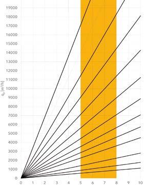
6000 m3/h / 35 m = 171 m3/h/m
Hole design
LV hole design chosen due to room category B (see p. 77)
Hole rows, static pressure and throw length
Input parameters from datasheet 12: 171 m3/h/m
Number of hole rows per side: 8
Static pressure: 105 Pa
Min. throw length l0.20 = 3.8 m
Air velocity at entrance to occopied zone
Current throw length in room: 12 m/4 + (4.1 m - 1.8 m) = 5.3 m

Isothermal air velocity after 5.3 m: viso = (3.8 m/5.3 m) x 0.20 m/s = 0.14 m/s
Flow model 1 (wall jet): viso = 2 x 0.14 m/s = 0.20 m/s
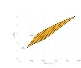
Pressure loss calculation
Ps,mid = 105 Pa
Pd,mid = ½ x r x (vmid)2 = ½ x 1.205 kg/m3 x (½ x 6.8 m/s)2 = 7 Pa
Pt,mid = Ps,mid + Pd,mid = 105 Pa + 7 Pa = 112 Pa
P t,start = 112 Pa (friction loss = 0 Pa)
P s,start = P t,start - Pd,start = 112 Pa - ½ x r x (6.8 m/s)2 = 85 Pa (ESP)
P t,start = 112 Pa < 120 Pa OK!
Noise calculation
Input parameters from datasheet 21: Pt,start = 112 Pa, basic sound power level: @ 43 dB(A)
Correction for length of duct and number of hole rows:
Input parameters from datasheet 22: number of hole rows in total = 16, L = 17.5 m
Correction: + 7.5 dB(A) + 3 dB(A)* = 10.5 dB(A)
Resulting sound power level per duct: 43 dB(A) + 10.5 dB(A) = 53.5 dB(A)
Resulting sound power level transmitted to room: 53.5 dB(A) + 3 dB(A)* = 56.5 dB(A)
*3 db(A) is added for the sound power level every time the number of ducts double.
Dimensioning: KE-DireJet System
The following input data is provided:
Room dimensions (L x W x H): 26 m x 8 m x 8 m
Centre of duct: 7.3 m above floor level
Number of sockets and location: 1 socket on the end wall
Inlet temperature and desired room temperature: 4°C / 4°C (isothermal)
Volume flow per socket: 5300 m³/h
Choice of material: ZeroWeave (impermeable)
Free jet required: ST-3 (free jet)
Maximum air velocity in near zone: 0.30 m/s
Total pressure available for textile ducts: 140 Pa
Room dimensions and layout
8 m 26 m 7.3 m 8 m
Calculation process
The following calculation process is used:
1. Determine the number and length of KE-DireJet ducts 2. Determine the duct diameter 3. Determine the volume flow per running metre of ducting 4. Determine the nozzle type 5. Determine the number of nozzles per metre, the static pressure and throw 6. Determine the air velocity at the entrance to the occupied zone 7. Calculate the pressure loss 8. Calculate the noise level
Number and length of ducts
1 socket = 1 duct
Room length: 26 m - Duct length 25 m
Duct diameter
Input parameters from datasheet 3: 5300 m³/h and max. 7-8 m/s for inlet velocity
Duct diameter: D = Ø560 mm, v = 6 m/s
Volume flow per running metre of ducting

5300 m3/h / 25 m = 212 m3/h/m
Choice of nozzle
A Ø18 mm nozzle is selected.
Number of nozzles, static pressure and throw length
Input parameters from datasheet 18: 212 m3/h/m
Number of nozzles per side: 10
Static pressure: 121 Pa
Min. throw length l0.30 = 6.0 m
Air velocity at entrance to occupied zone
Current throw length in room: 6.0 m (150° downward slant)
Isothermal air velocity after 6.0 m: viso = 0.30 m/s
Pressure loss calculation
Ps,mid = 121 Pa
Pd,mid = ½ x r x (vmid)2 = ½ x 1.205 kg/m3 x (½ x 6 m/s)2 = 6 Pa
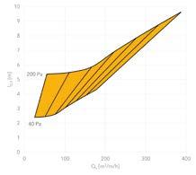
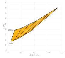
Pt,mid = Ps,mid + Pd,mid = 121 Pa +6 Pa = 127 Pa
P t,start = 127 Pa (friction loss = 0 Pa)
P s,start = P t,start - Pd,start = 127 Pa - ½ x r x (6 m/s)2 = 106 Pa (ESP)
P t,start = 127 Pa < 140 Pa OK!
Noise calculation
Input parameters from datasheet 21: Pt,start = 127 Pa, basic sound power level: = 48 dB(A)
Correction for length of duct and number of nozzles:
Input parameters from datasheet 24: Number of nozzles per metre in total = 20, L = 25 m
Correction: + 7 dB(A)
Resulting sound power level transmitted to room: 48 dB(A) + 7 dB(A) = 55 dB(A)
Lifetime Extension.
In line with our entire foundation on sustainability and the way we develop our solutions, we develop products and offer services that contribute to the longest possible product life.

Lifetime Extension.
Unlike products that are designed to fail after a certain time, our strategy of life extension is based on the fact that we will develop solutions and services that contribute to longer life and more value in our products such as maintenance, repairability, energy optimisation and recycling.
It’s our goal that all our products have an average lifetime of minimum 20-25 years, if properly maintained. KE Fibertec has manufactured and supplied Textile Based Ventilation systems since 1974 so we have the experience and knowledge to provide the necessary lifetime extension to all KE systems. It is a good investment which is clearly shown in payback period and our Life Cycle calculations. A well-operated and well-maintained system provides:

• A better indoor climate
• Less energy costs over time
• Longer product life of up to 20-25 years

• More satisfied customers
• Sustainable solution (material can be recycled after 20-25 years)
Energy optimisation by IoT.

KE Fibertec continuously works on developing and optimisation our products and services, so that we are always at the forefront of the latest technology and can offer energy-efficient solutions to our customers at all times. Below we have listed a few of the initiatives that we have been working on in order to provide a more energy-friendly solution to the market.
Monitoring of air pressure.
Dirty and therefore inefficient ventilation ducts is one of the biggest threats to a healthy indoor climate at a work site. A clean textile duct provides healthy indoor climate and energy savings that will benefit not only the environment, but also the operating economy of the plant.
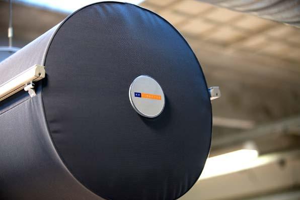
With the intelligent sensor system InTex you are able to monitor the air pressure and temperature in the textile duct and be notified when the duct needs to be washed. That way you are guaranteed an energy-efficient solution and will get optimal washing frequency in relation to fan pressure loss.
Highest dust holding capacity on the market.

The material GreenWeave has longer washing intervals with staple fibre yarns that ensure largest possible textile surface with a dust holding capacity of more than 25 g/m3 textile surface according to EN779: 2012.
Lower pressure drop.

With a textile based ventilation solution you are able to have a lower system pressure drop compared to traditional steel based ventilation with distribution ducts (balancing dampers not necessary).
Nozzles ensure 100% active and directional air flow.
From a ventilation technology perspective, the KE-DireJet System can be regarded as an active high impulse system for mixing ventilation and with a 25% lower pressure compared to holes and microperforation.
InTex - an intelligent sensor system
Diffuse or directional ventilation.
KE Fibertec offers ceiling panels for diffuse or directional ventilation with DFC baffles. Creating a healthy indoor air quality in rooms with low ceilings can be a challenge,however, it is possible with FBS panels. The panels can be designed down to 10 Pa.
Life Cycle Cost (LCC) Calculation.

Often, the most expensive material is not the most expensive solution when considering the entire product life cycle cost. KE Fibertec can provide a Life Cycle Cost (LCC) calculation, which provide a total financial overview. There are five main costs on which we base the calculation of the total lifetime costs of a TBV system:
• Initial investment for the TBV system
• Installation costs
• Operating costs (fan operation)
• Service costs (primarily washing and maintenance)
• End of life cost (taking the system down and scrap it)
The operating and service costs will be the most expensive part, the longer the system is in operation.
Fast and easy installation.
We have listed some of the main advantages you get by choosing a textile based ventilation system from KE Fibertec:
Fewer installation hours.
Compared to more traditional steel ducting solutions with air diffusors you will obtain a much faster installation by choosing a textile based ventilation system. It varies per type of installation, but TBV-ducts are typically 25-60% faster to install compared with the complete mounting of steel ducts, air diffusors and commissioning. Apart from a much lower weight and easier handling, all KE Fibertec’s suspension rails are delivered cut on exact lengths. It makes the complete handling and installation time much easier and quicker than for similar systems.
Better ergonomics with lower weight.
Our materials weigh 260-330 g/m2 which is much lighter than steel ducts and in total give a much lower weight per duct. At the same time textile ducts are much easier to handle and to transport as they are folded and packed in cartons of a maximum weight of 25 kg. With textile based ducting you get a solution with a unique image and an aesthetic expression. The system is self-balancing and a damper is not necessary.
Easy commissioning.

KE Fibertec provides a full documentation report together with the order confirmation. All necessary data for how to commission our system are available.
A KE Fibertec system with plenum and branch ducts is designed to be almost self-balancing. No dampers are needed, which saves many hours during commissioning.
Facts on operating costs. Typical factors that influence the clogging up and estimated washing intervals are:
• Outdoor air quality (actual particle rate at the building site)
• Choice of correct prefilter (KE Fibertec recommends at least filter class M6 or MERV 13)
• Air handler run time per year (the run time is very important for the energy consumption and washing frequency)
• The dust holding capacity of the ducts (the amount of dust that the fabric can accumulate when it operates at a specific air pressure rise)
Example:
Duct Ø560 mm Length: 35,000 mm Installations per room: 2 ducts

Calculation of installation time
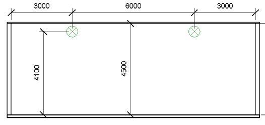
Steel duct Textile duct Installation (hours) 23.6 17.5


Calculation of weight
Steel duct Textile duct
System weight (kg) 789.0 102.7 Heaviest unit (kg) 32.6 4.7
The best warranty on the market.
KE Fibertec AS offers four different types of warranty. An overview of the complete warranty terms and conditions is available at ke-fibertec.com/download/terms. The terms there will always take precedence.
Period of warranty in years (from date of invoice)
Materials1) 4) Zips / bulbs4)
GreenWeave, GW
Antistatic, Nomex, MultiWeave and InTex® monitoring combined with a maintenance agreement with KE Fibertec2)
GreenWeave, GW
Antistatic, Nomex and MultiWeave without a maintenance agreement with KE Fibertec
ZeroWeave
FBS panels
DireJet nozzles and other accessories4) Suspension material4)
Design and technical function
InTex® electronics batteries3)
15 years 15 years 15 years 15 years 1 year 2 years3)
10 years 10 years 10 years 10 years 1 year 2 years3)
5 years 5 years 5 years 5 years 1 year N/A
10 years 10 years N/A 10 years 1 year N/A
1) We refer to the general KE material specifications regarding tolerances and properties. 2) See separate warranty conditions for InTex® concerning rules of maintenance agreements. 3) We do not offer any warranty on batteries. 4) TBV systems installed in aggressive environments such as swimming pool facilities, dairies, galvanizing plants etc. are covered by the standard 5 year warranty. The extended 10 year product warranty only applies by written agreement with KE Fibertec.
Design warranty on technical operation.
KE Fibertec provides a 1-year design warranty on the technical operation of the system (pulsations, pressure loss and air velocity in the occupied zone) provided that this has been specifically stated in the order confirmation. In all cases, KE Fibertec reserves the right to perform measurements on the ventilation system on its own before accepting a design warranty claim.
Liability for defective performance.
If defects are found in KE Fibertec’s delivery in relation to what has been stated in the order confirmation, KE Fibertec’s liability for defective performance will apply for a period of 12 months from the start-up date, but no longer than 18 months from date of invoice.
Within this period KE Fibertec undertakes to rectify all defects in the delivered goods by repair or replacement as KE Fibertec deems fit.
KE Fibertec’s obligation to remedy defects is subject to the customer being able to prove that the delivered systems are defective and is able to document that the TBV systems have been stored, installed and put into operation properly and in compliance with the provided mounting instruction and Intro leaflet found in the “INFO” carton.
Product warranty.
If - against expectations - a defect should occur on a KE Fibertec TBV system within the warranty period stated in the table, KE Fibertec must be notified at once in order to minimise the damage.
The product warranty covers repairs or replacement (of KE Fibertec’s choice) of the defective duct system inclusive of freight, if any, to the installation site.
The warranty is void if the TBV system is incorrectly installed, repaired or modified by third party or by failure to maintain the duct systems according to KE Fibertec’s washing and maintenance instructions.
The warranty does not cover printed artwork/logos, labels or changes in colour, by grey shading or normal ageing.
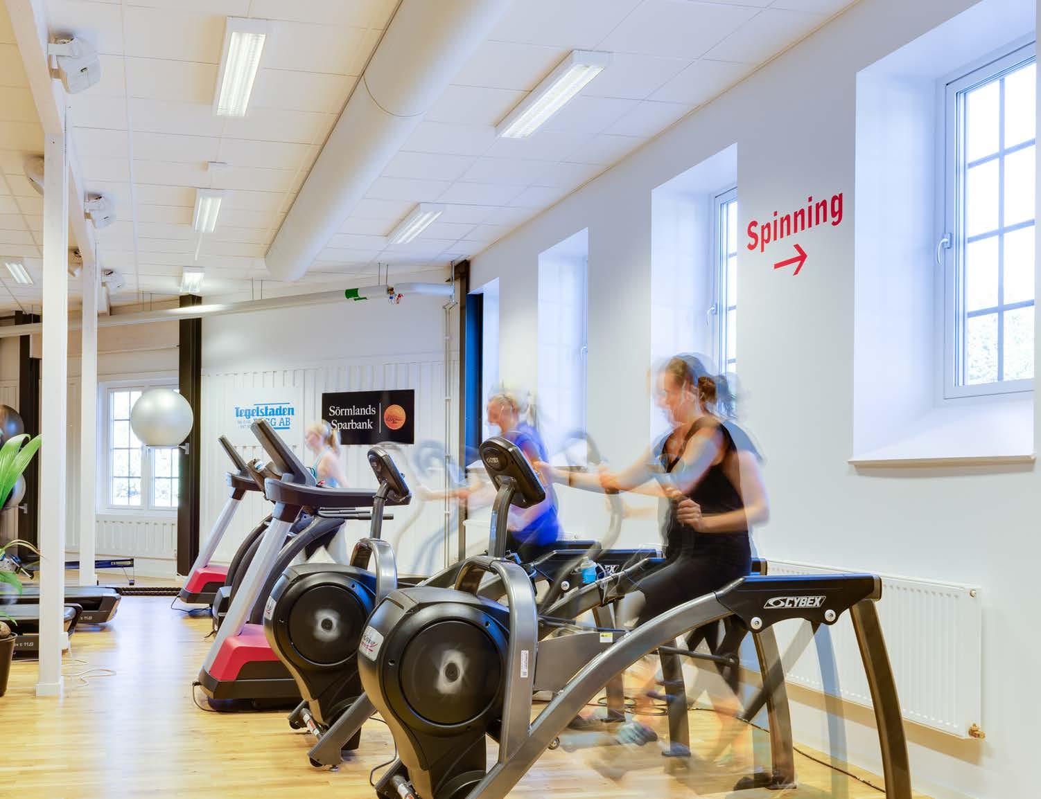
Service and Maintenance.
All ventilation ducts require regular cleaning and maintenance. With textile ducting you have the benefits of easy maintenance that will ensure long-lasting functionality.


Good indoor climate for everyone’s benefit.
Buildings are ventilated in order to create a satisfactory indoor climate and guarantee a healthy working environment. It is therefore crucial that the buildings we occupy have a good indoor climate. Poor air quality affects our ability to work as it can make it difficult for us to concentrate and irritate our eyes and nose. A poor indoor climate can therefore increase the level of absence through sickness, which has major financial consequences both for the individual company and for society as a whole.
All ventilation ducts (steel or textile) require regular washing and maintenance. The advantage of textile ducting is that the ducts can easily be taken down for washing again and again so that functionality and hygiene are as new.

Dust Holding Capacity and washing intervals.
No matter how well the air is prefiltered, a certain amount of dust particles will always exist - partly deposited in ventilation ducts and fittings, and partly entering the room via the supply air of the ventilating unit. A KE textile duct filters out much of the residual suspended dust. In rooms with recirculation this is important for the quality of air since prefilters are hardly ever applied to filter the amount of air being recirculated. KE Fibertec offers two types of materials, MultiWeave and GreenWeave with high dust holding capacity and long washing intervals.
Spare sets.
In environments that require frequent washing of the ducts it may be a good idea to have a spare set ready. In that way you can install clean textile ducts and take down the soiled ducts in one process. That saves both time and money and the running of the ventilation system will not be interrupted for maintenance.
Long service life.
KE Fibertec’s low impulse systems can have a long service life if used properly. They have been developed so that they can be washed and serviced up to 100 times without decreasing their porosity compared to that of a new product. The following precautions must be observed to achieve the longest possible service life:
• The systems must hang freely so that the textile material does not rub against fixed objects, thereby causing damage.
• The systems must hang still as pulsations can damage the textile material. Violent jolts must also be avoided when starting up the system as this can cause the suspension system or textile duct to come loose or sustain serious damage.
• The systems must be protected when being installed and removed so that the textile materials are not damaged.
• Outdoor air passing through the systems must be prefiltered – Class M6 – to avoid them quickly becoming clogged up.
• The systems must be washed, centrifuged and dried according to KE Fibertec’s instructions to prevent them from getting damaged.
Washing service.
KE Fibertec in Denmark and a number of KE Fibertec partners have established inhouse professional washing services of textile duct systems and ensure professional and correct handling of the duct systems.
KE Fibertec offers customised washing concepts that ensure a good washing result, no matter where the ducts are installed.
Washing Service.All-round service concepts.
KE Fibertec’s washing and maintenance services include a number of options:
Documentation report included in service
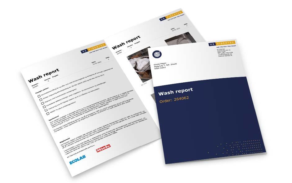

Often, the most expensive material is not the most expensive solution when considering the entire product life cycle. We make an inspection of all textile ducts before wash and make a quality control ensuring the right treatment and to make any repairs. We offer a complete report after each wash explaining the treatment and as documentation of the wash.
Permeability measurement
Measurement of material air permeability before and after washing to ensure proper functionality.
Removal and installation
If you are short of manpower, KE Fibertec can help with the removal of the ducts before washing and the subsequent installation of the clean ducts.
Safe and easy storage
KE Fibertec will store your spare ducts. In this way they are guaranteed to be kept dry and safe until needed - it’s easy and cheap.
Antibacterial treatment
For the food industry we offer an environmental friendly antibacterial treatment without silver ions. The Antibac-E treatment is approved according to EN-ISO 20645:2004 and EN ISO 20743:2013 for 3 washing cycles before the treatment must be renewed.
Please note that our washing concept is run with different concept set-ups depending on the location of our partners. For further information please contact us at info@ke-fibertec.dk.
Warranty up to 15 years
KE Fibertec can offer an extended warranty scheme that covers the product for up to 15 years. This is on the condition that an Intex® system is installed to monitor air pressure and temperature in the textile duct and that KE Fibertec is in charge of washing and maintenance of the textile ducts
Datasheets.
Tools that will assist you in the design phase of a textile duct solution.


d 1.8 m
Determining the maximum cooling load per metre
1400
1200
1000
800
600
400
200
φ [W/m] ΔT [˚C]
Room category C
Room category A Room category B
0
1600 0 2 4 6 8 10
Correction, K, for distance from duct and heat source types
A B C
Distance d [m] Normal Low Floor Normal Low Floor Normal Low Floor
1.0 0.32 0.23 0.17 0.44 0.32 0.23 0.53 0.38 0.28 1.5 0.60 0.44 0.32 0.69 0.50 0.36 0.75 0.54 0.39 2.0 0.89 0.65 0.47 0.92 0.67 0.48 0.93 0.68 0.49 2.5 1.16 0.85 0.61 1.11 0.80 0.58 1.10 0.80 0.57 3.0 1.43 1.04 0.75 1.31 0.95 0.69 1.24 0.90 0.65 3.5 1.68 1.22 0.88 1.48 1.08 0.78 1.38 1.00 0.72 4.0 1.91 1.39 1.00 1.65 1.20 0.86 1.50 1.09 0.79 4.5 2.14 1.56 1.12 1.80 1.31 0.94 1.61 1.17 0.84 5.0 2.36 1.72 1.24 1.94 1.41 1.02 1.72 1.25 0.90 5.5 2.57 1.87 1.35 2.08 1.51 1.09 1.82 1.32 0.95 6.0 2.77 2.02 1.45 2.21 1.60 1.16 1.91 1.39 1.00 6.5 2.97 2.16 1.56 2.33 1.69 1.22 2.00 1.45 1.05 7.0 3.15 2.29 1.65 2.45 1.78 1.28 2.08 1.51 1.09
Determining the maximum cooling load per metre
L0,15
q p [m 3 /h] Length of nearzone [m]
Determining length of near zone of 0.15 m/s, 0.20 m/s and 0.25 m/s 100
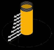
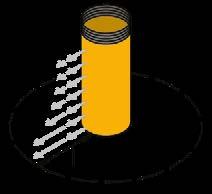
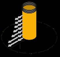
10000 1,00 10,00
1000
Datasheet 3 V0
Determining the duct diameter (round)
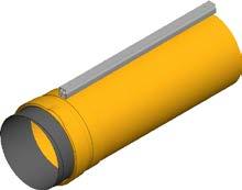
Q v [m 3 /h]
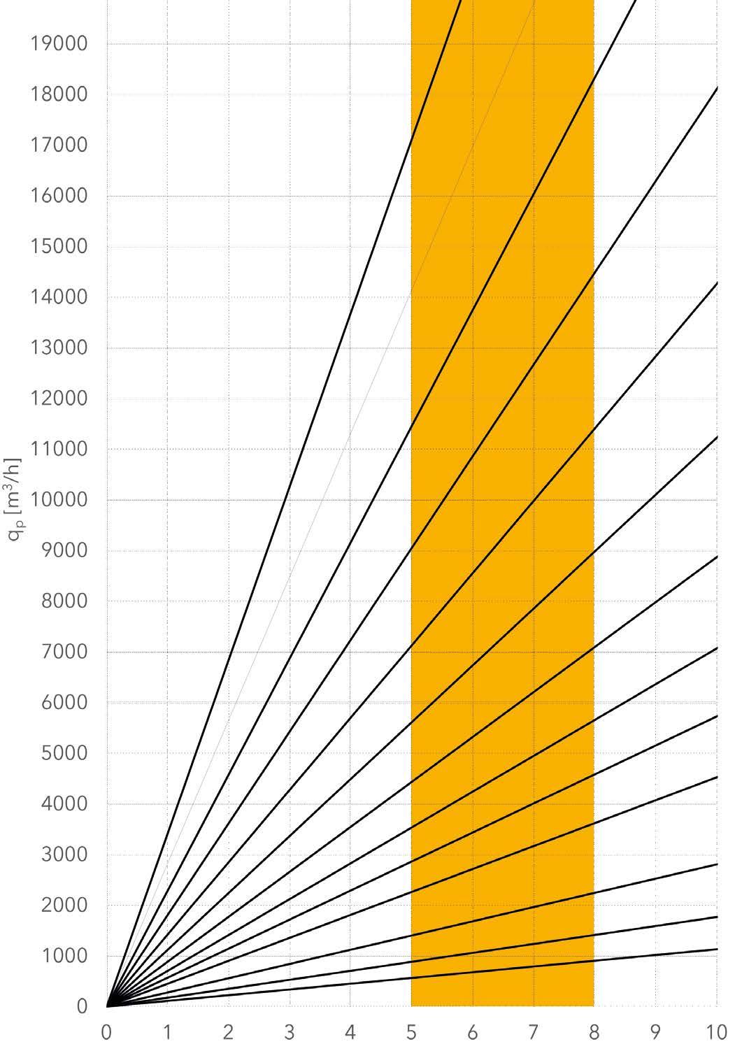
Inlet velocity [m/s]
Ø1000
Ø1100 Ø900 Ø800 Ø710 Ø630 Ø560 Ø500 Ø250
Ø450 Ø400 Ø315 Ø200
Q v [m 3 /h]
Determining the duct diameter (round)

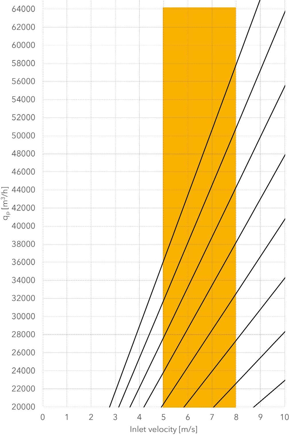
V0
Ø1600 Ø1500 Ø1400 Ø1300 Ø1200 Ø1100 Ø1000 Ø900
Inlet velocity [m/s]
Datasheet 5
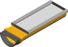
Determining the duct diameter (half-round)
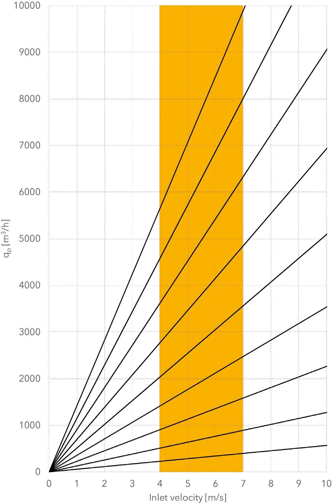
V0
Ø1000 Ø900 Ø800 Ø700 Ø600 Ø500 Ø400 Ø300 Ø200
P s [Pa]
GW50 GW150 GW200 GWA200 GW320 GWA320 GW500 GWA500 GW780 GW1380
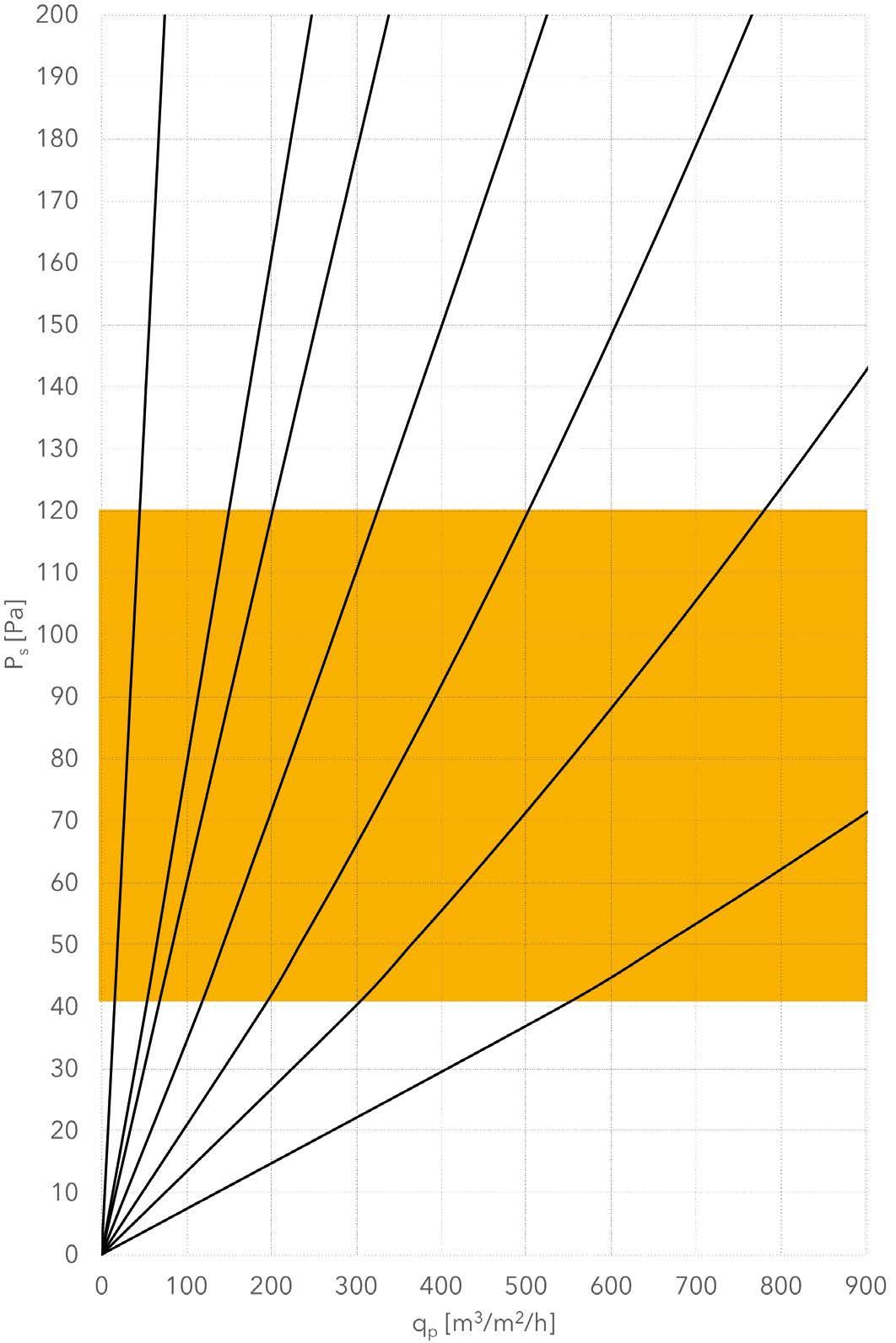
diagram MultiWeave
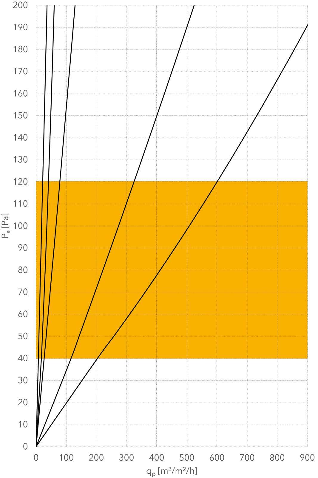
MW20 MW40 MW80 MW320 MW600
P s [Pa]
Pressure loss diagram KE-Inject LV, MV and Jet
LV MV JET
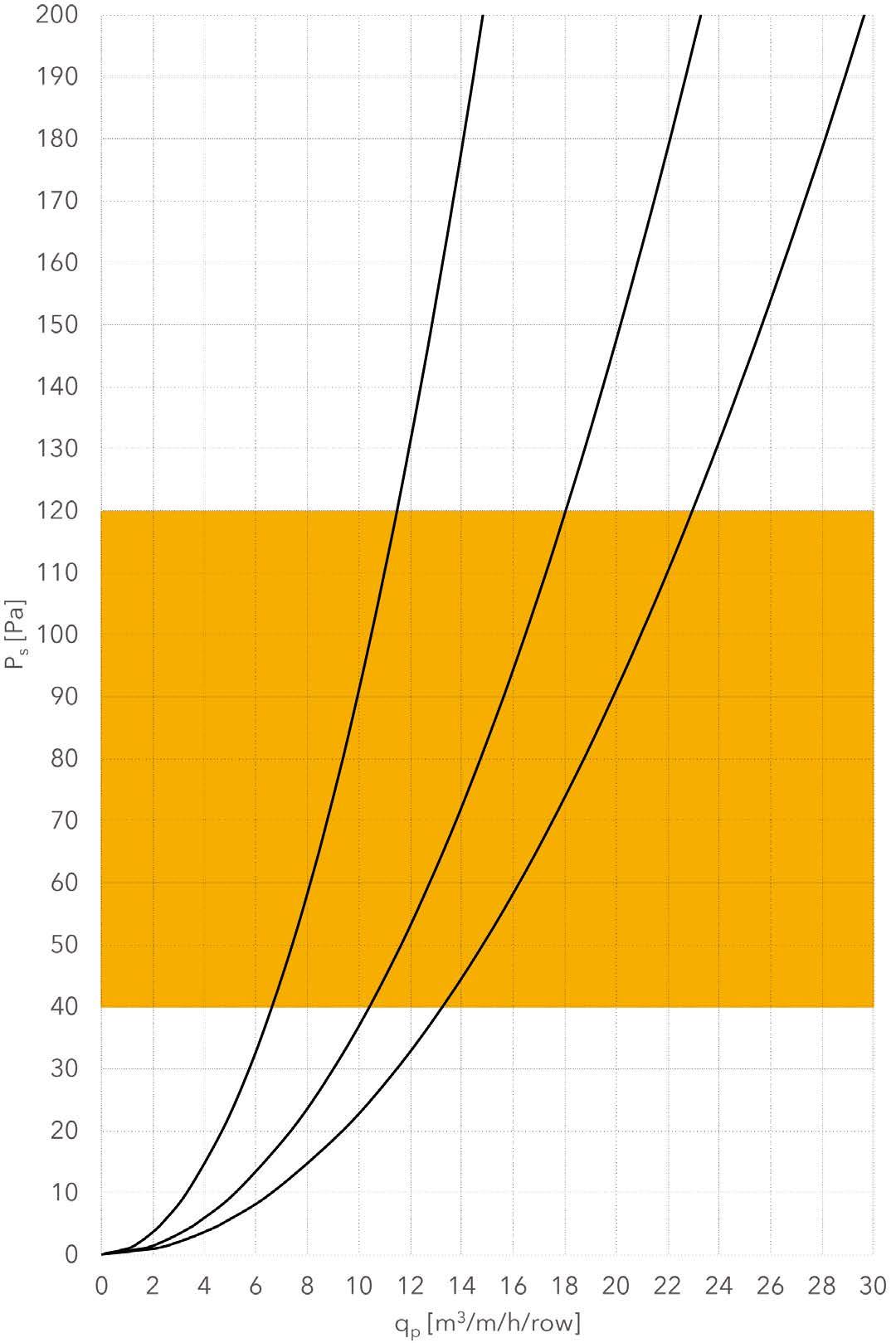
P s [Pa]
190
180
170
160
150
140
130
120
110
Ø6 Ø12 Ø25
100
90
80
70
60
50
40
30
Pressure loss diagram Inject Flex M Ø6 Ø12 Ø25 0 0,0 0,0 0,0 1 0,1 0,4 1,9 2 0,1 0,5 2,5 3 0,2 0,6 2,9 4 0,2 0,7 3,2 5 0,2 0,8 3,5 10 0,3 1,1 4,7 20 0,4 1,5 6,4 30 0,5 1,8 7,7 40 0,5 2,1 8,8 50 0,6 2,3 9,8 60 0,6 2,5 10,7 70 0,7 2,7 11,5 80 0,7 2,9 12,3 90 0,8 3,0 13,0 100 0,8 3,2 13,7 110 0,9 3,4 14,3 120 0,9 3,5 14,9 130 0,9 3,6 15,5 140 1,0 3,8 16,1 150 1,0 3,9 16,6 160 1,0 4,0 17,1 170 1,1 4,2 17,6 180 1,1 4,3 18,1 190 1,1 4,4 18,6 200 1,2 4,5 19,1 0
200 0 5 10 15 20 25
20
10
P s [ Pa] qp [m3/m/h/hole] Q v [m3/h/hole]
P s [Pa]
190
180
170
160
150
140
130
120
110
100
90
80
70
60
50
40
30
20
Pressure loss diagram Inject Flex XL Ø35 Ø50 Ø70 0 0,0 0,0 0,0 1 3,9 8,2 17,4 2 4,9 10,2 21,4 3 5,6 11,9 24,6 4 6,3 13,3 27,5 5 6,9 14,5 30,0 10 9,3 19,4 40,2 20 12,6 26,3 54,9 30 15,2 31,7 66,3 40 17,3 36,2 75,9 50 19,3 40,1 84,4 60 21,0 43,7 92,1 70 22,6 47,1 99,2 80 24,1 50,1 105,8 90 25,4 53,0 112,0 100 26,8 55,8 117,9 110 28,0 58,4 123,5 120 29,2 60,8 128,8 130 30,4 63,2 133,9 140 31,5 65,5 138,8 150 32,5 67,7 143,6 160 33,5 69,9 148,2 170 34,5 72,0 152,7 180 35,5 74,0 157,0 190 36,5 75,9 161,2 200 37,4 77,9 165,3 0
P s [ Pa] qp [m3/m/h/hole]
10
Ø35 Ø50 Ø70 Q v [m3/h/hole]
200 0 50 100 150 200
KE-Inject LV - Throw length for free jet at 0.20 m/s
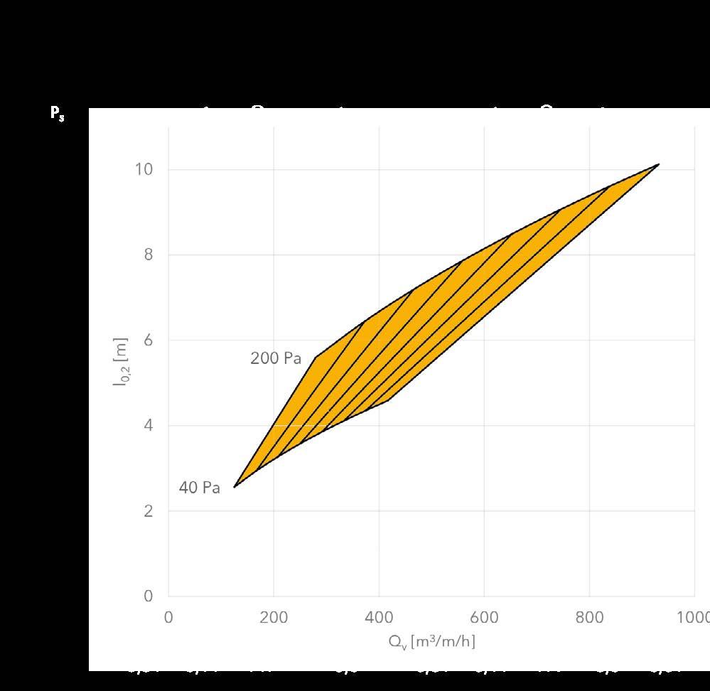


KE-Inject MV - Throw length for free jet at 0.20 m/s
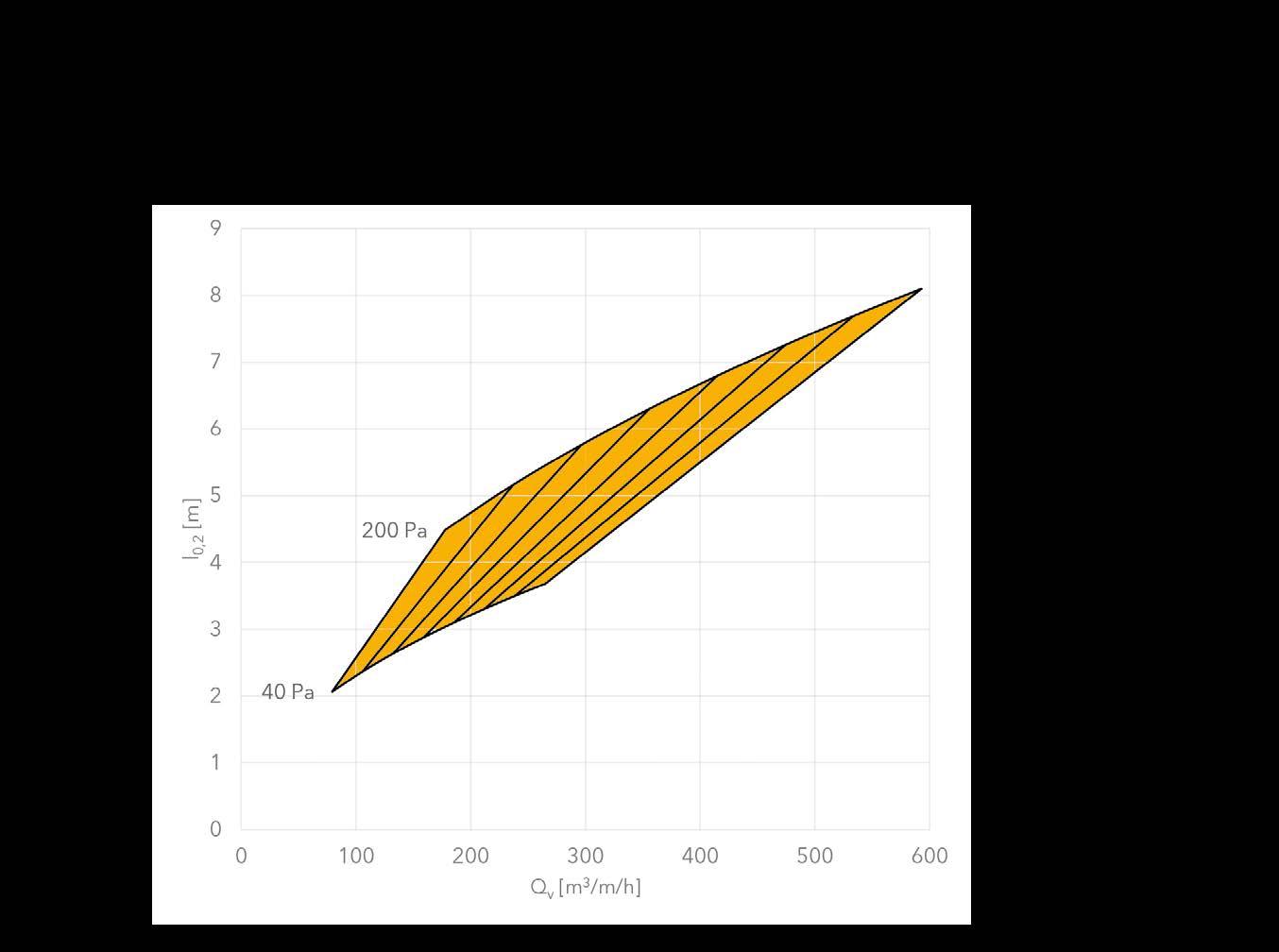
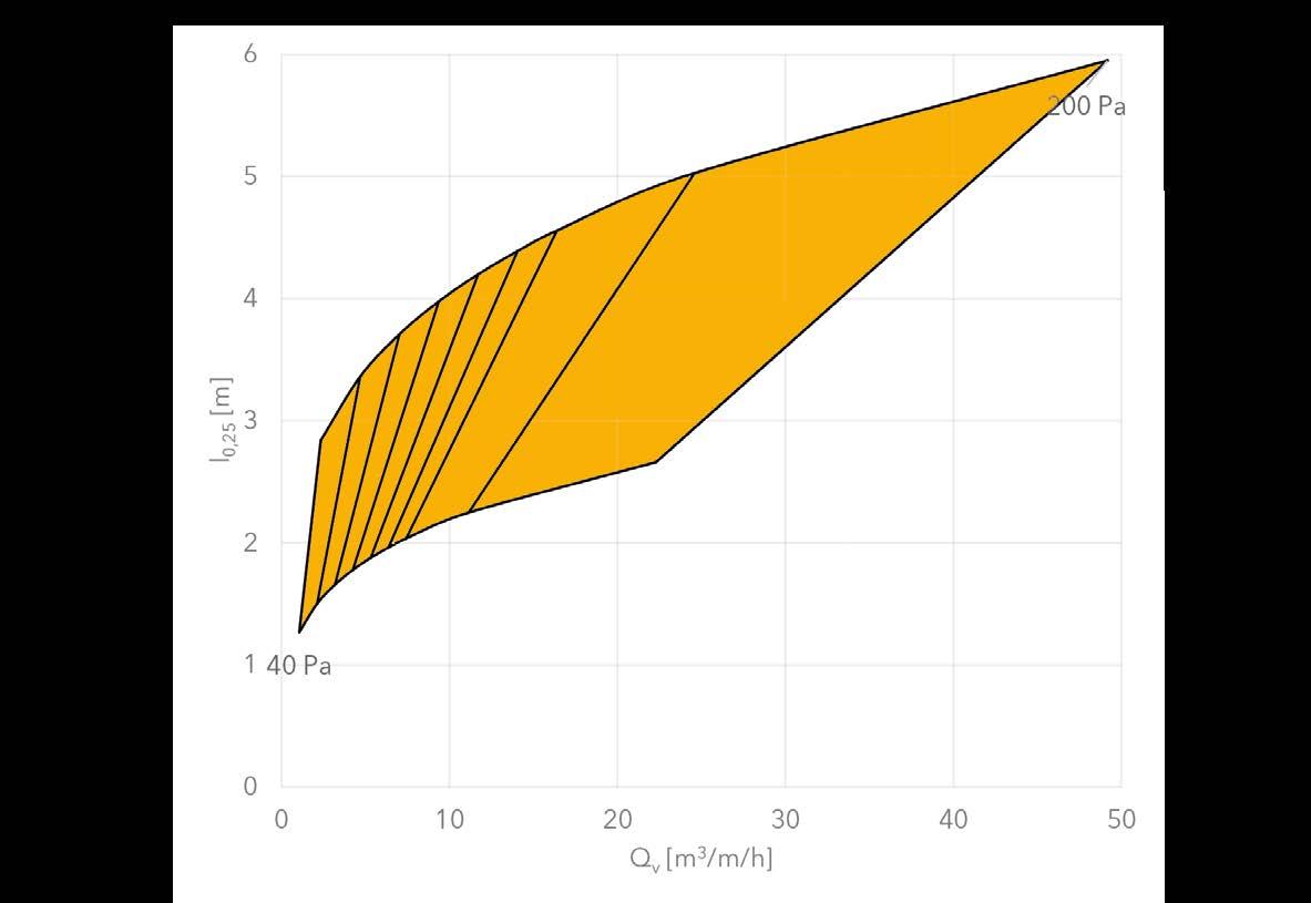


Throw length for Inject Flex M 12 mm for free jet at 0.30 m/s
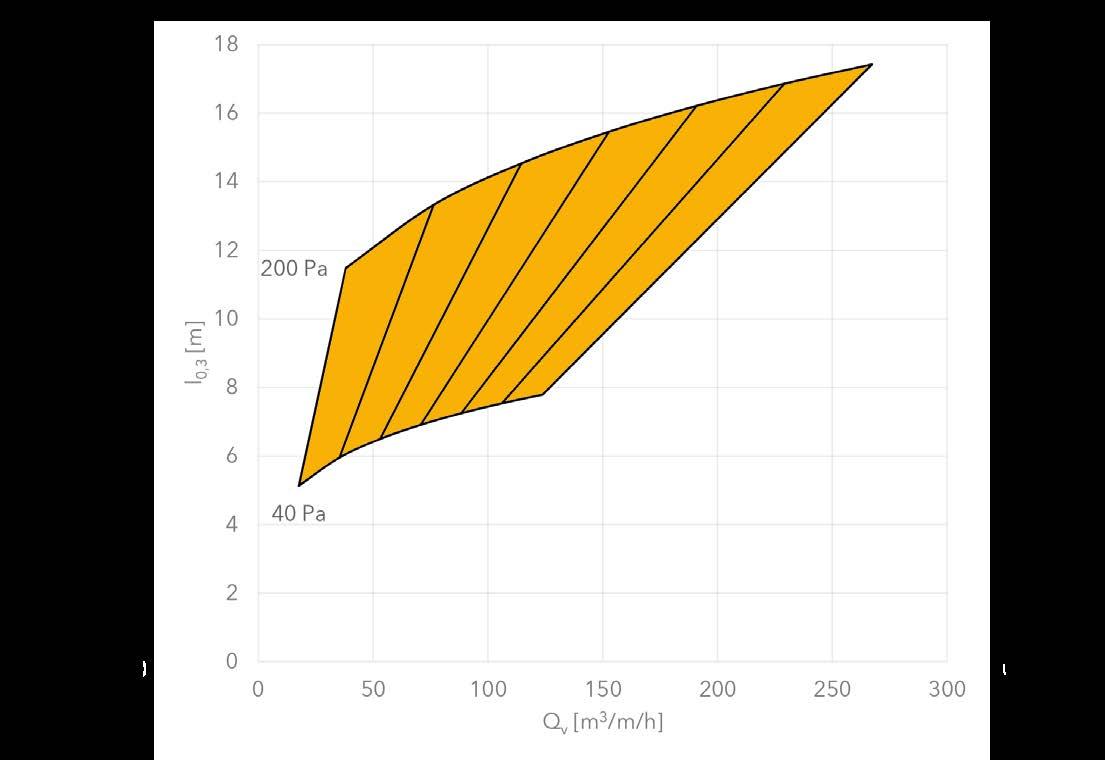
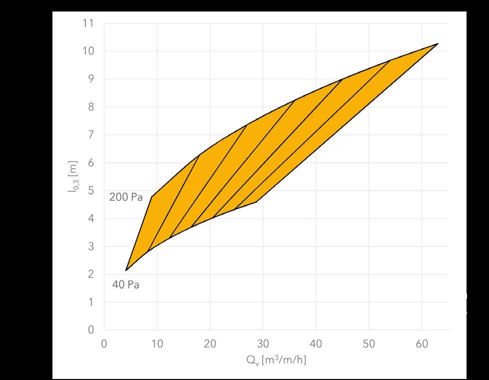


Throw length for Inject Flex M 25 mm for free jet at 0.30 m/s
2-sided 2-sided
Throw length for Inject Flex XL 35 mm for free jet at 0.30 m/s


Throw length for Inject Flex XL 50 mm for free jet at 0.30 m/s
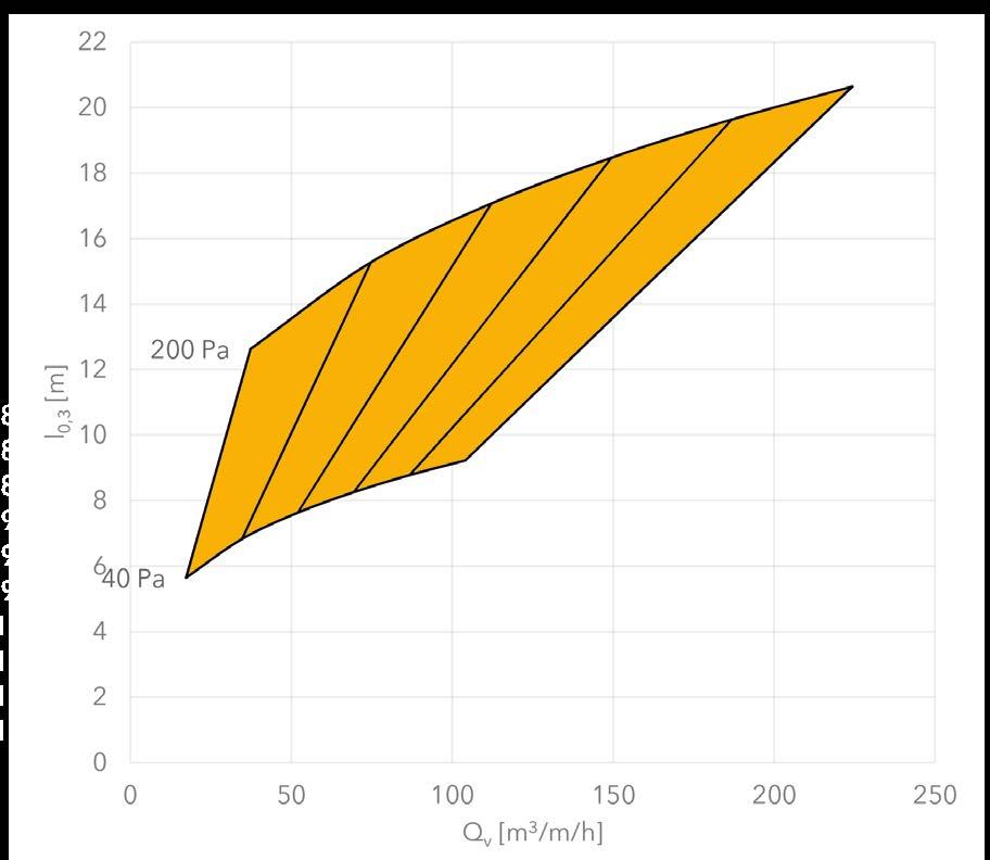
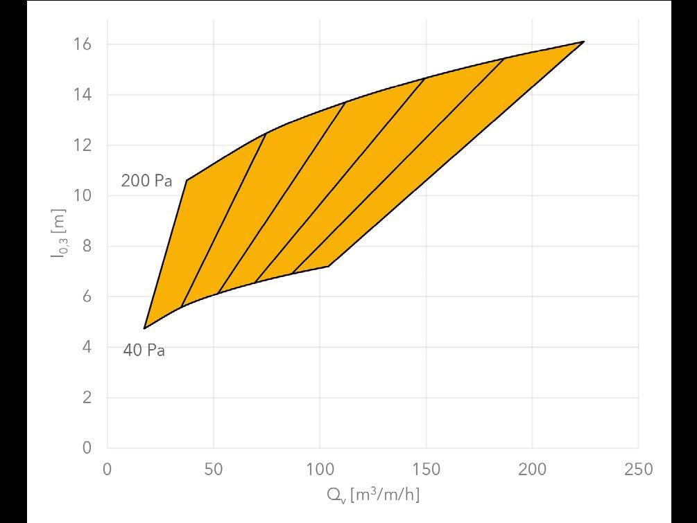
Pressure loss diagram KE-DireJet Ø12, Ø18 and Ø24 mm
Pressure loss diagram KE-DireJet Ø48 and Ø60 mm
Throw length for KE-DireJet Ø12 mm for free jet at 0.30 m/s d = 2 d = 4 d = 6 d = 8 d = 10 d = 12 d = 14


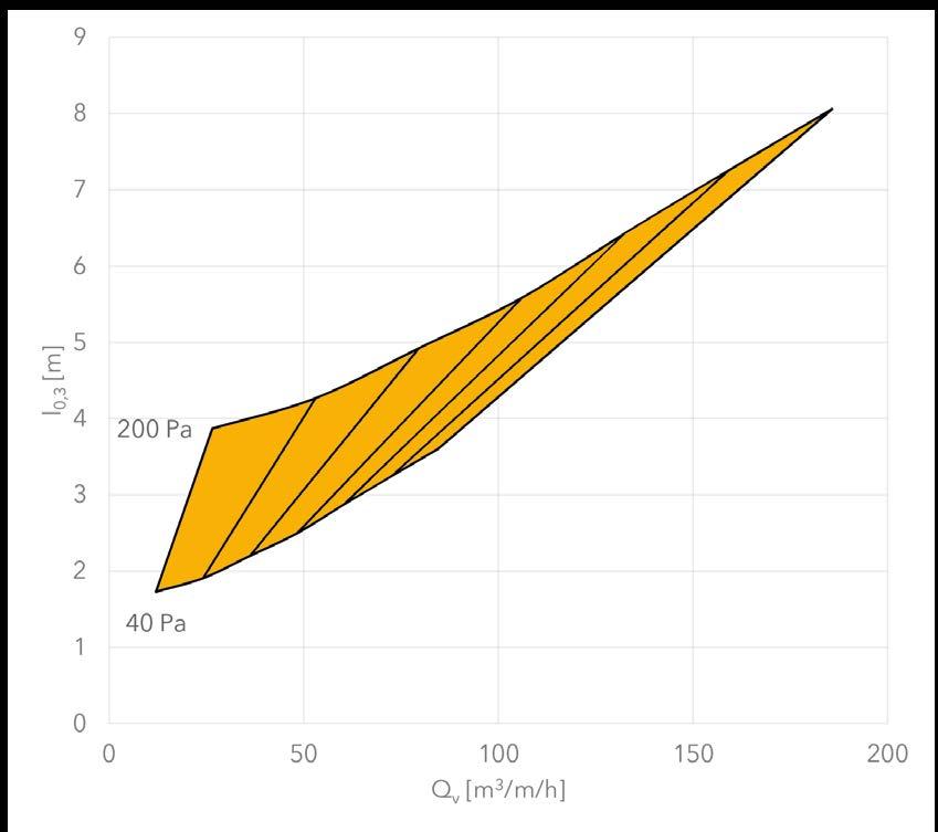
Throw length for KE-DireJet Ø18 mm for free jet at 0.30 m/s d = 2 d = 4 d = 6 d = 8 d = 10 d = 12 d = 14
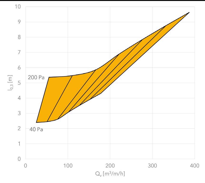


Throw length for KE-DireJet Ø48 mm for free jet at 0.30 m/s
d = 1 d = 2 d = 3 d = 4 d = 5 d = 6 d = 1 d = 2 d = 3 d = 4 d = 5 d = 6


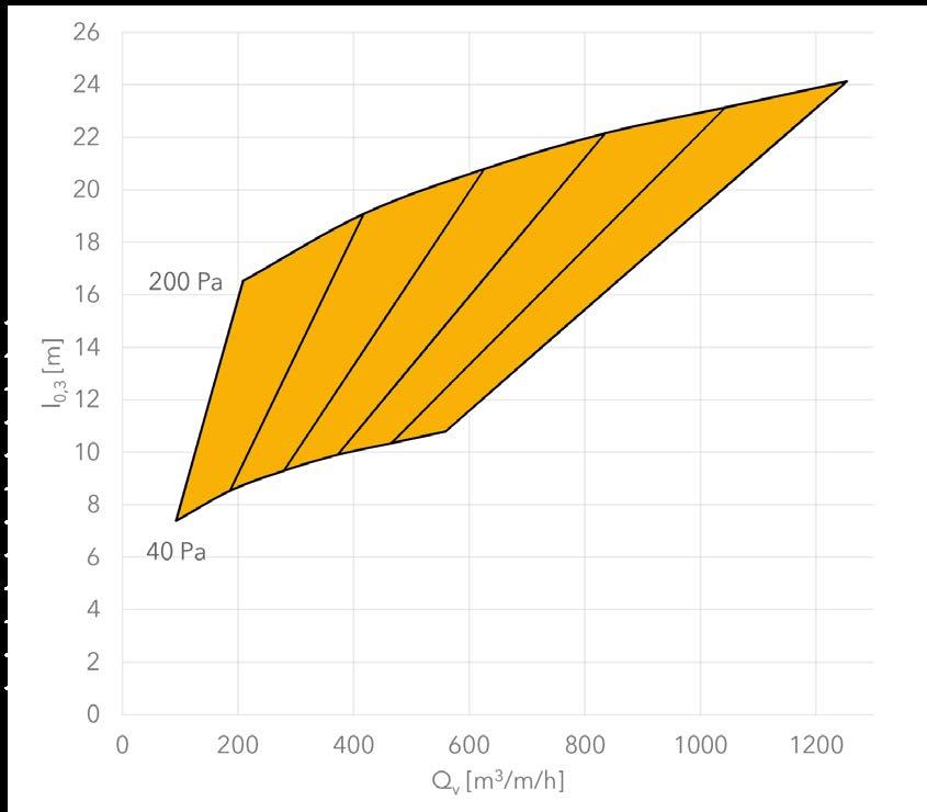
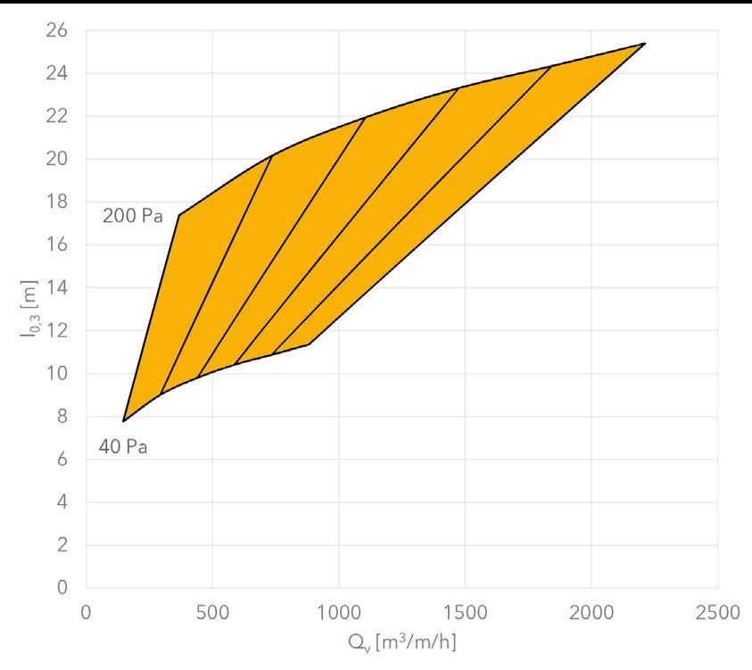
Throw length for KE-DireJet Ø60 mm for free jet at 0.30 m/s
2-sided 2-sided
Datasheet
Determining basic Sound Power Level
Correction of sound power levels - Inject Flex S 4 mm
LV / Inject Flex S 4 low
2.5 5 7.5 10 12.5 15 17.5 20 22.5 25 2 -10.0 -7.0 -5.2 -4.0 -3.0 -2.2 -1.5 -1.0 -0.5 0.0
4 -7.0 -4.0 -2.2 -1.0 0.0 0.8 1.5 2.0 2.6 3.0 6 -5.2 -2.2 -0.5 0.8 1.8 2.6 3.2 3.8 4.3 4.8 8 -4.0 -1.0 0.8 2.0 3.0 3.8 4.5 5.1 5.6 6.0 10 -3.0 0.0 1.8 3.0 4.0 4.8 5.4 6.0 6.5 7.0 12 -2.2 0.8 2.6 3.8 4.8 5.6 6.2 6.8 7.3 7.8 14 -1.5 1.5 3.2 4.5 5.4 6.2 6.9 7.5 8.0 8.5 16 -1.0 2.0 3.8 5.1 6.0 6.8 7.5 8.1 8.6 9.0 18 -0.5 2.6 4.3 5.6 6.5 7.3 8.0 8.6 9.1 9.5 20 0.0 3.0 4.8 6.0 7.0 7.8 8.5 9.0 9.5 10.0 MV
2.5 5 7.5 10 12.5 15 17.5 20 22.5 25 2 -8.0 -5.0 -3.3 -2.0 -1.0 -0.3 0.4 1.0 1.5 2.0 4 -5.0 -2.0 -0.3 1.0 2.0 2.8 3.4 4.0 4.5 5.0 6 -3.3 -0.3 1.5 2.8 3.7 4.5 5.2 5.8 6.3 6.7 8 -2.0 1.0 2.8 4.0 5.0 5.8 6.4 7.0 7.5 8.0 10 -1.0 2.0 3.7 5.0 5.9 6.7 7.4 8.0 8.5 9.0 12 -0.3 2.8 4.5 5.8 6.7 7.5 8.2 8.8 9.3 9.7 14 0.4 3.4 5.2 6.4 7.4 8.2 8.9 9.4 10.0 10.4 16 1.0 4.0 5.8 7.0 8.0 8.8 9.4 10.0 10.5 11.0 18 1.5 4.5 6.3 7.5 8.5 9.3 10.0 10.5 11.0 11.5 20 2.0 5.0 6.7 8.0 9.0 9.7 10.4 11.0 11.5 12.0 JET / Inject Flex S 4 high
Correction of sound power levels - Inject Flex
Holes per m / Length of duct in m Ø6
2.5 5 7.5 10 12.5 15 17.5 20 22.5 25
2 -15.7 -9.7 -6.2 -3.7 -1.7 -0.2 1.2 2.3 3.4 4.3
4 -12.7 -6.7 -3.2 -0.7 1.3 2.9 4.2 5.4 6.4 7.3 6 -10.9 -4.9 -1.4 1.1 3.0 4.6 6.0 7.1 8.1 9.1
8 -9.7 -3.7 -0.2 2.3 4.3 5.9 7.2 8.4 9.4 10.3 10 -8.7 -2.7 0.8 3.3 5.2 6.8 8.2 9.3 10.4 11.3 12 -7.9 -1.9 1.6 4.1 6.0 7.6 9.0 10.1 11.1 12.1
14 -7.3 -1.2 2.3 4.8 6.7 8.3 9.6 10.8 11.8 12.7 16 -6.7 -0.7 2.9 5.4 7.3 8.9 10.2 11.4 12.4 13.3 18 -6.2 -0.2 3.4 5.9 7.8 9.4 10.7 11.9 12.9 13.8 20 -5.7 0.3 3.8 6.3 8.3 9.8 11.2 12.3 13.4 14.3
Holes per m / Length of duct in m Ø12
2.5 5 7.5 10 12.5 15 17.5 20 22.5 25 2 -9.7 -3.7 -0.2 2.3 4.3 5.9 7.2 8.4 9.4 10.3 4 -6.7 -0.7 2.9 5.4 7.3 8.9 10.2 11.4 12.4 13.3 6 -4.9 1.1 4.6 7.1 9.1 10.6 12.0 13.1 14.2 15.1 8 -3.7 2.3 5.9 8.4 10.3 11.9 13.2 14.4 15.4 16.3 10 -2.7 3.3 6.8 9.3 11.3 12.9 14.2 15.4 16.4 17.3 12 -1.9 4.1 7.6 10.1 12.1 13.6 15.0 16.1 17.2 18.1 14 -1.2 4.8 8.3 10.8 12.7 14.3 15.7 16.8 17.8 18.8 16 -0.7 5.4 8.9 11.4 13.3 14.9 16.2 17.4 18.4 19.3 18 -0.2 5.9 9.4 11.9 13.8 15.4 16.7 17.9 18.9 19.8 20 0.3 6.3 9.8 12.3 14.3 15.9 17.2 18.4 19.4 20.3
Holes per m / Length of duct in m Ø35
7.5 10 12.5
17.5 20 22.5 25 1 -3.4 2.6 6.1 8.6 10.6 12.2 13.5 14.6 15.7 16.6 2 -0.4 5.6 9.1 11.6 13.6 15.2 16.5 17.7 18.7 19.6 3 1.4 7.4 10.9 13.4 15.3 16.9 18.3 19.4 20.4 21.4 4 2.6 8.6 12.2 14.6 16.6 18.2 19.5 20.7 21.7 22.6 5 3.6 9.6 13.1 15.6 17.6 19.1 20.5 21.6 22.7 23.6 6 4.4 10.4 13.9 16.4 18.3 19.9 21.3 22.4 23.5 24.4 7 5.0 11.1 14.6 17.1 19.0 20.6 21.9 23.1 24.1 25.0 8 5.6 11.6 15.2 17.7 19.6 21.2 22.5 23.7 24.7 25.6 9 6.1 12.2 15.7 18.2 20.1 21.7 23.0 24.2 25.2 26.1 10 6.6 12.6 16.1 18.6 20.6 22.2 23.5 24.6 25.7 26.6
Correction of sound power levels - KE-DireJet and KE-Low Impulse
Nozzles per m / Length of duct in m
2.5 5 7.5 10 12.5 15 17.5 20 22..5 25
2 -13.0 -10.0 -8.2 -7.0 -6.0 -5.2 -4.6 -4.0 -3.5 -3.0
4 -10.0 -7.0 -5.2 -4.0 -3.0 -2.2 -1.5 -1.0 -0.5 0.0
6 -8.2 -5.2 -3.5 -2.2 -1.2 -0.5 0.2 0.8 1.3 1.8
8 -7.0 -4.0 -2.2 -1.0 0.0 0.8 1.5 2.0 2.6 3.0 10 -6.0 -3.0 -1.2 0.0 1.0 1.8 2.4 3.0 3.5 4.0 12 -5.2 -2.2 -0.5 0.8 1.8 2.6 3.2 3.8 4.3 4.8
Nozzles Correction / Length of duct in m Low Impulse
14 -4.6 -1.5 0.2 1.5 2.4 3.2 3.9 4.5 5.0 5.4 16 -4.0 -1.0 0.8 2.0 3.0 3.8 4.5 5.1 5.6 6.0 18 -3.5 -0.5 1.3 2.6 3.5 4.3 5.0 5.6 6.1 6.5 20 -3.0 0.0 1.8 3.0 4.0 4.8 5.4 6.0 6.5 7.0 22 -2.6 0.4 2.2 3.4 4.4 5.2 5.9 6.4 6.9 7.4 24 -2.2 0.8 2.6 3.8 4.8 5.6 6.2 6.8 7.3 7.8 26 -1.9 1.1 2.9 4.1 5.1 5.9 6.6 7.2 7.7 8.1 28 -1.5 1.5 3.2 4.5 5.4 6.2 6.9 7.5 8.0 8.5 30 -1.2 1.8 3.5 4.8 5.7 6.5 7.2 7.8 8.3 8.8 32 -1.0 2.0 3.8 5.1 6.0 6.8 7.5 8.1 8.6 9.0 34 -0.7 2.3 4.1 5.3 6.3 7.1 7.7 8.3 8.8 9.3 36 -0.5 2.6 4.3 5.6 6.5 7.3 8.0 8.6 9.1 9.5 38 -0.2 2.8 4.5 5.8 6.8 7.6 8.2 8.8 9.3 9.8 40 0.0 3.0 4.8 6.0 7.0 7.8 8.5 9.0 9.5 10.0 2.5 5 7.5 10 12.5 15 17.5 20 22.5 25 -3.0 0.0 1.8 3.0 4.0 4.8 5.4 6.0 6.5 7.0
Equivalent sound absorption area [m² Sabine]
Determination of room attenuation
Datasheet 25 1
Eqivalent sound absorption area [m 2 Sabine] Room Volume [m3] -10 -8 -6 -4 -2 0 2 4 6 8 10 12 14 16 18 20 22 24 0,2 2
100
Veryattenuatedroom(αm =0.40) Attenuatedroom(αm =0.25) Normalroom(αm =0.15) Hardroom(αm =0.10) Veryhardroom(αm =0.05) 0.3 0.2 0.4 0.5 0.6 0.7 0.8 0.9 1 2 4 6 8 10
1000 10 100 1000 10000
10
RD [dB(A)] r/D0,5
500 m2 Sabine 200 m2 Sabine 100 m2 Sabine 50 m2 Sabine 20 m2 Sabine 10 m2 Sabine 5 m2 Sabine 2 m2 Sabine 1 m2 Sabine r/ D
FBS Panels


