Counter Modules
Process for connecting encoder count sensors Illustration The TSX CTY 4A module wiring is as follows. For a TSX CTY 2A or TSX CTY 2C module, only the elements related to channels 0 and 1 should be connected.
Description of the different connection elements Process for connecting the encoder to the standard 15-pin SUB-D connector, located on the TSX CTY 2A/4A/2C module. Given the various encoder types, it is your responsibility to carry out this connection, which consists of:
a connector for linking to the encoder (determined by the connector on the encoder in use; normally a female 12-pin DIN connector), a standard male 15-pin SUB-D connector, to connect to the female 15-pin SUB-D connector on the TSX CTY 2A/4A/2C module. This connector is available under reference TSX CAP S15, a cable: with twisted pairs (gauge 26) and shielding for an incremental encoder with standard RS 422 line transmitter outputs or an absolute encoder, multi-conductor (gauge 24) with shielding for an incremental encoder with Totem Pole outputs.
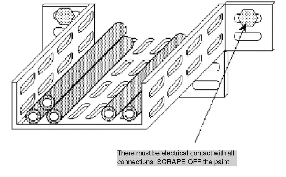
The type of cable shielding should be "braid and foil". The cables should be completely supported to ensure the "braid and foil" is connected to the ground connection of each connector. Connection of the cable to the two connectors can vary according to the type of encoder supply (5 VDC or 10…30 VDC) and the type of outputs (RS 422, Totem Pole). By way of an example, certain types of connection are described in the following pages.
250
33002439 10/2019