30
C HAPTE R 1 Terminology, Positioning, and Imaging Principles
POSITIONING PRINCIPLES 1
Evaluation Criteria
The goal of every technologist should be to take not just a “passable” radiograph but rather an optimal one that can be evaluated by a definable standard, as described under evaluation criteria. An example of a four-part radiographic image evaluation as used in this text for a lateral forearm is shown on the right. The positioning photo and the resulting optimal radiograph (Figs. 1-99 and 1-100) are shown for this lateral forearm, as described in Chapter 4.
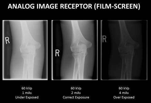
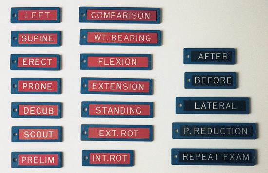
EVALUATION CRITERIA FORMAT The technologist should review and compare radiographs using this standard to determine how close to an optimal image was achieved. A systematic method of learning how to critique radiographs is to break the evaluation down into these four parts. 1. Anatomy demonstrated: Describes precisely what anatomic parts and structures should be clearly visualized on that image (radiograph). 2. Position: Generally evaluates four issues: (1) placement of body part in relationship to the IR, (2) positioning factors that are important for the projection, (3) correct centering of anatomy, and (4) collimation 3. Exposure: Describes how exposure factors or technique (kilovoltage [kV], milliamperage [mA], and time) can be evaluated for optimum exposure for that body part. No motion is a first priority, and a description of how the presence or absence of motion can be determined is listed. (Motion is included with exposure criteria because exposure time is the primary controlling factor for motion.) 4. Image markers: A fourth area of evaluation involves image markers. Anatomic side markers, “Right” or “Left,” patient position, or time markers must be placed correctly before exposure so that they are not superimposed over essential anatomy.
Fig. 1-99 Accurate positioning for lateral forearm.
SAMPLE LATERAL FOREARM CRITERIA EVALUATION CRITERIA
Anatomy Demonstrated: • Lateral projection of entire radius and ulna; proximal row of carpals, elbow, and distal end of humerus; and pertinent soft tissues such as fat pads and stripes of wrist and elbow joints Position: • Long axis of forearm aligned with long axis of IR • Elbow flexed 90° • No rotation from true lateral as evidenced by the following: • Head of the ulna should be superimposed over the radius • Humeral epicondyles should be superimposed • Radial head should superimpose the coronoid process with radial tuberosity seen in profile • Collimation to area of interest Exposure: • Optimum density (brightness) and contrast with no motion will reveal sharp cortical margins and clear, bony trabecular markings and fat pads and stripes of the wrist and elbow joints Image Markers: • Patient identification, R or L side marker, and patient position or time markers should be placed so that they are not superimposed over essential anatomy
Fig. 1-100 Lateral forearm.


