
TEMPLE MOBILITY MASTER PLAN 2022

Anti-Discrimination Notice
The City of Temple is committed to providing a safe and nondiscriminatory living and working environment for all members of the public and City employees. The City provides equal opportunity to all employees, applicants for employment, and the public regardless of race, color, sex, religion, national origin, age, disability, genetic information, veteran status, sexual orientation, or gender identity. The City will promptly investigate and resolve all complaints of discrimination, harassment (including sexual harassment), and related retaliation in accordance with applicable federal and state laws.
The City’s response to allegations of discrimination, harassment, and related retaliation will be 1) prompt and equitable; 2) intended to prevent the recurrence of any harassment; and 3) intended to remedy its discriminatory effects, as appropriate. A substantiated allegation of such conduct will result in disciplinary action, up to and including separation from the City. Vendors, contractors and third parties who commit discrimination, harassment or related retaliation may have their relationship with the City terminated and their privileges of doing business with the City withdrawn. Please contact the office of the City Manager at 254.298.5600 to file a complaint.
i
Acknowledgements
City Council Members
Tim Davis, Mayor
Jessica Walker, District 1
Judy Morales, District 2 (Mayor Pro Tem)
Susan Long, District 3
Wendell Williams, District 4
Steering Committee
Brynn Myers, City Manager
Jason Deckman, Senior Transportation Planner, Co-Project Manager
Richard Wilson, City Engineer, Co-Project Manager
Kenny Henderson, Transportation Director
Don Bond, Director of Public Works
Emily Parks, Manager of Public Relations
Kevin Beavers, Director of Parks & Recreation
Chuck Ramm, Asst. Director of Parks & Recreation
Traci Barnard, Director of Finance
Bryan Daniel, Board of Directors, Reinvestment Zone #1
Uryan Nelson, Director, Killeen-Temple MPO
Heather Bates, Director of Marketing & Communications
Kiara Nowlin, Communications & Public Relations Manager
Sean Parker, Director, Draughon-Miller Central Texas Regional Airport
Nancy Glover, Director of Housing and Community Development
Mike Hemker, Asst. Director of Parks & Recreation
Sherry Pogor, Financial Analyst
James McGill, Planning Manager, Killeen-Temple MPO
David Holmes, Operations Manager, Draughon-Miller Central Texas Regional Airport
David Olson, Asst. City Manager
Kendra Coufal, Planning Services Manager, CTCOG
The City of Temple would like to thank the following businesses for their help with spreading the word about MMP public meeting events and information:
Twice Apon A Clothes Line
The Hub
2nd Street Emporium
Pignetti's
The Casino
Sports World
Impressions By Criswell
First Furniture & TV
Texell
EZ Pawn
Vintage & Antiques
Trenos Pizza
First Street Roasters
Mexiko Cafe
Gandys Barber Shop
Relics Antiques
Empire Seed
Alchemy Salon
Ras Kitchen
Bird Creek Burger
Johnnie's Cleaning & Tailoring
Hawkins Personnel Group
KPA
Darling Decor
Security Finance
Hair & Lash Junkie
The City of Temple would like to give a special thanks to all of the staff at the Wilson Park Recreation Center for their help and extraordinary effort in making the January MMP Public Meeting such a great success.
ii
RESOLUTION NO. 2022-0145-R
A RESOLUTION OF THE CITY COUNCIL OF THE CITY OF TEMPLE, TEXAS, AUTHORIZING APPROVING THE MOBILITY MASTER PLAN FOR THE CITY OF TEMPLE; AND PROVIDING AN OPEN MEETINGS CLAUSE.
Whereas, the City of Temple began work on the first Mobility Master Plan (MMP) in January 2021 and due to the wide-ranging nature of transportation planning, a team was assembled to provide specific expertise in a variety of subject areas;
Whereas, the project managers on the city side were selected from the Engineering and Planning Departments - the consultant team was made up of Alliance Transportation Group, Kasberg-Patrick Engineers, Garver USA, and Machi Mobility;
Whereas, the project managers and consultants leveraged their knowledge of public engagement, data analysis, traffic modeling, and engineering designs - a steering committee met quarterly to provide guidance on the plan vision as well as feedback on the technical documents;
Whereas, the Mobility Master Plan is both a data-driven and community-centered document. Work began with an assessment of the current state of transportation in the City of Temple - existing city plans were evaluated to incorporate transportation-related initiatives from those documents, and this was followed by several discussions with professional staff, key stakeholders, and city residents;
Whereas, the feedback received in these meetings informed a statement of the vision, goals, and objectives and an interactive online map allowed people to draw features and leave comments about specific locations and challenges - the project team held two well-attended public meetings – one virtual meeting conducted online in May 2021 and a hybrid meeting held at Wilson Park Community Center in January 2022;
Whereas, specific input on transit, congestion, active transportation, safety and freight was gathered during this phase of the plan - safety analysis and traffic simulations were conducted to provide a vision of how the transportation network may perform, as growth takes place and new projects are implemented;
Whereas, the Mobility Master Plan incorporates all modes of transportation in a strategic vision to meet the needs of the community in a multi-faceted document that addresses the challenges of balancing automobile traffic, pedestrian and bicycle trips, public transit, and commercial freight movement - a data-driven plan, the MMP is based on analysis of past accidents, current level of service and computer modeling of traffic flow and intersection function;
Whereas, the Mobility Master Plan lays out recommendations for needed mobility improvements and provides action steps to be used in implementing this plan - roadway, transit, and active transportation projects will be advanced and programmed based on an iterative feedback process between elected officials, city staff, community leaders, and citizen input;
iii 1 4 3 6 3
DocuSign Envelope ID: 1E34B5B4-C452-4471-B6C2-A5095408A90C
Whereas, recommended actions include assembling a consolidate list of projects that are based on ongoing needs assessment, and making strategic budget decisions about which projects will be built, and in which fiscal year they will be funded;
Whereas, the Mobility Master Plan project team has made every effort to solicit public input and stakeholder feedback into this plan - in the interest of transparency and convenience, the draft chapters of the plan have been published online at www.templetx.gov/mobility;
Whereas, Staff recommends Council approve the Mobility Master Plan for the City of Temple;
Whereas, the fiscal year 2022 – 2028 Capital Improvement Program includes $30,000,000 in planned funding dedicated to prioritizing future project recommendations resulting from the Mobility Master Plan; and
Whereas, the City Council has considered the matter and deems it in the public interest to authorize this action.
NOW, THEREFORE, BE IT RESOLVED BY THE CITY COUNCIL OF THE CITY OF TEMPLE, TEXAS, THAT:
Part 1: Findings. All of the above premises are hereby found to be true and correct legislative and factual findings of the City Council of the City of Temple, Texas, and they are hereby approved and incorporated into the body of this Resolution as if copied in their entirety.
Part 2: The City Council approves the Mobility Master Plan for the City of Temple.

Part 3: It is hereby officially found and determined that the meeting at which this Resolution was passed was open to the public as required and that public notice of the time, place, and purpose of said meeting was given as required by the Open Meetings Act.
PASSED AND APPROVED this the 16th day of June, 2022.
THE CITY OF TEMPLE, TEXAS
TIMOTHY A. DAVIS, Mayor
ATTEST: APPROVED AS TO FORM:


 Jana Lewellen
City Secretary
Kathryn H. Davis
City Attorney
Jana Lewellen
City Secretary
Kathryn H. Davis
City Attorney
iv 2 4 3 6 3
DocuSign Envelope ID: 1E34B5B4-C452-4471-B6C2-A5095408A90C
v Table of Contents 1. INTRODUCTION .................................................................................................................................................................................................................. 1 1.1 What is a Mobility Master Plan? ............................................................................................................................................................................................................................................... 1 1.2 Planning Area .......................................................................................................................................................................................................................................................................................4 1.3 Past Planning Initiatives 4 2. VISION, GOALS, AND OBJECTIVES ............................................................................................................................................................................. 7 2.1 Vision Statement ................................................................................................................................................................................................................................................................................ 7 2.2 Goals and Objectives 7 3. OVERVIEW OF THE PUBLIC INVOLVEMENT PROCESS ...................................................................................................................................... 11 3.1 Meetings 12 3.2 Tools ........................................................................................................................................................................................................................................................................................................... 14 3.3 What We Heard 15 4. SUMMARY OF EXISTING CONDITIONS .................................................................................................................................................................... 19 4.1 Roadway Network Configuration and Condition ................................................................................................................................................................................................. 20 4.2 Multimodal Transportation System Performance Statistics 25 4.3 Safety Performance 39 4.4 Travel Demand Management ........................................................................................................................................................................................................................................... 44 5. EVALUATION OF FUTURE CONDITIONS .................................................................................................................................................................47 5.1 Anticipated Growth Patterns 47 5.2 Transportation Demand Modeling.................................................................................................................................................................................................................................. 50 5.3 Future Operational Deficiencies Analysis 52 5.4 Planned Multimodal Developments ............................................................................................................................................................................................................................. 53 6. SCENARIO ANALYSES .................................................................................................................................................................................................. 59 6.1 Scenario 1-3: Vehicular Transportation ...........................................................................................................................................................................................................................60 6.2 Scenario 4: Transit Vision 65 6.3 Scenario 5: Active Transportation Improvements ............................................................................................................................................................................................... 69 6.4 Scenario 6: Emerging Technology & TSMO 72 7. TEMPLE ACTIVE TRANSPORTATION PLAN ............................................................................................................................................................ 77 7.1 What is Active Transportation? 77 7.2 The Active Vision ............................................................................................................................................................................................................................................................................. 78 7.3 Public and Stakeholder Feedback 79
vi 7.4 Key Principles .................................................................................................................................................................................................................................................................................... 79 7.5 Who Are We Planning For? 80 7.6 Existing Facilities ............................................................................................................................................................................................................................................................................. 81 7.7 Integrating Parks and Trails Plan with Transportation System 83 7.8 Neighborhood Plan Recommendations .................................................................................................................................................................................................................... 85 7.9 Network Development and Recommendations 86 7.10 Active Transportation Plan Map..................................................................................................................................................................................................................................... 107 7.11 Action Plan 109 8. TRANSIT VISION PLAN ................................................................................................................................................................................................. 113 8.1 Transit Vision 113 8.2 Existing Transit in Temple ...................................................................................................................................................................................................................................................... 114 8.3 Market Analysis 115 8.4 Transit Service Improvement Recommendations ............................................................................................................................................................................................ 118 8.5 Implementation Steps 131 8.6 Action Plan ........................................................................................................................................................................................................................................................................................135 9. THOROUGHFARE PLAN .............................................................................................................................................................................................. 139 9.1 Legal Authority................................................................................................................................................................................................................................................................................ 139 9.2 Functional Classifications 139 9.3 Typical Street Section Design Characteristics........................................................................................................................................................................................................ 141 9.4 Proposed Thoroughfare Plan Amendments 160 10. MOBILITY RECOMMENDATIONS ............................................................................................................................................................................. 163 10.1 Intersection Recommendations..................................................................................................................................................................................................................................... 164 10.2 Roadway Recommendations 171 10.3 Multimodal Recommendations .................................................................................................................................................................................................................................... 176 10.4 Adopted Transportation-Related Design Standards .................................................................................................................................................................................... 184 10.5 Transportation Demand Management 185 10.6 Emerging Technologies ....................................................................................................................................................................................................................................................... 186 10.7 Freight Transportation Recommendations 188 10.8 Safety ................................................................................................................................................................................................................................................................................................... 189 11. IMPLEMENTATION PLAN ........................................................................................................................................................................................... 195 11.1 Project Delivery Process 195 11.2 Funding and Financing Strategies ..............................................................................................................................................................................................................................200 11.3 Decision Making and Conflict Resolution 209
vii 11.4 MMP Implementation Plan and the Mobility CIP ............................................................................................................................................................................................ 217 12. MOBILITY CAPITAL IMPROVEMENT PLAN ........................................................................................................................................................... 221 12.1 Introduction..................................................................................................................................................................................................................................................................................... 221 12.2 Mobility Capital Improvement Program 221 12.3 Mobility Capital Improvement Program Project Narrative...................................................................................................................................................................... 224 12.4 Mobility Capital Improvement Funding Schedule 230 APPENDIX A .........................................................................................................................................................................................................................237 Public Involvement Technical Memorandum ............................................................................................................................................................................................................... 237 APPENDIX B ........................................................................................................................................................................................................................ 263 Comprehensive System Assessment Technical Memorandum ...................................................................................................................................................................... 263 APPENDIX C ........................................................................................................................................................................................................................ 263 Scenario Analysis Technical Memorandum 263
List of Figures
viii
Figure 1.1: City of Temple MMP Study Area 3 Figure 3.1: Public Involvement Schedule ................................................................................................................................................................................................................................ 11 Figure 3.2: Results of Comments Received on the Interactive Mapping Tool 15 Figure 3.3: Interests - Items the Public Wants to See Added or Improved ................................................................................................................................................. 16 Figure 3.4: Concerns - Issues the Public Sees 16 Figure 4.1: Temple Subarea Level-of-Service - 2015 Existing Conditions ...................................................................................................................................................... 22 Figure 4.2: 2021 AM Peak Delay 24 Figure 4.3: 2021 PM Peak Delay ..................................................................................................................................................................................................................................................... 24 Figure 4.4: The HOP Existing Fixed Routes 26 Figure 4.5: HOP Service Categories ........................................................................................................................................................................................................................................... 26 Figure 4.6: Targeted Transit Riders and Market Served 29 Figure 4.7: Population and Employment Served by Transit .................................................................................................................................................................................. 30 Figure 4.8: Existing Active Transportation Facilities 32 Figure 4.9: Bicycle Level of Traffic Stress................................................................................................................................................................................................................................ 34 Figure 4.10: Texas Rail and Freight Network 37 Figure 4.11: Truck Parking Demand and Utilization at Publicly Owned and Privately Owned Truck Parking Locations ...................................... 38 Figure 4.12: Crash Summary by Severity, 2016-2020 ..................................................................................................................................................................................................... 39 Figure 4.13: 5-Year Crash Rates by Segment 40 Figure 4.14: Active Transportation Crashes by Severity .............................................................................................................................................................................................. 43 Figure 5.1: The City of Temple and ETJ Total Population (2005-2045) 47 Figure 5.2: Percent Change in Population and Employment from 2019 to 2045 by TAZ ............................................................................................................. 48 Figure 5.3: Temple Subarea Level of Service – 2045 Forecast Conditions 51 Figure 5.4: Likely Active Transportation Demand .......................................................................................................................................................................................................... 54 Figure 5.5: Existing and Planned Bicycle Facilities 55 Figure 6.1: Temple Subarea Level of Service – 2045 No-Build Condition......................................................................................................................................................64 Figure 6.2: Temple Subarea Level of Service – 2045 Scenario 3 64 Figure 6.3: Transit Alternative A..................................................................................................................................................................................................................................................... 66 Figure 6.4: Transit Alternative B 67 Figure 6.5: Transit Alternative C.....................................................................................................................................................................................................................................................68 Figure 6.6: Context A Example - Meredith Dunbar School 70 Figure 6.7: Context B Example - W. 25th Street................................................................................................................................................................................................................. 71
ix Figure 7.1: Sidewalk Condition in the City of Temple ..................................................................................................................................................................................................... 81 Figure 7.2: Existing Sidewalk and Trails 82 Figure 7.3: Greenway Trail Typical Cross Section ............................................................................................................................................................................................................. 83 Figure 7.4: Thoroughfare Connector Trails Typical Cross Section 84 Figure 7.5: Neighborhood Connector Trail Typical Cross Section ..................................................................................................................................................................... 84 Figure 7.6: Neighborhood Plan - Pedestrian Connector Example 85 Figure 7.7: Neighborhood Plan - Bicycle Boulevard Example .............................................................................................................................................................................. 85 Figure 7.8: Bicycle Network Four-Step Process 90 Figure 7.9: Bike Network Facility Examples .......................................................................................................................................................................................................................... 91 Figure 7.10: Decision Tree for the All Ages and Abilities and Secondary Bicycle Network 92 Figure 7.11: Proposed Bicycle Network Development Layers ................................................................................................................................................................................. 93 Figure 7.12: Proposed All Ages and Abilities and Secondary Bicycle Network .........................................................................................................................................94 Figure 7.13: Pedestrian Sidewalk Prioritization and Pedestrian Connectors 100 Figure 7.14: Safe Routes to School Sidewalk Density.................................................................................................................................................................................................. 102 Figure 7.15: Active Transportation Recommendation 108 Figure 8.1: Population and Employment Served by Transit .................................................................................................................................................................................. 116 Figure 8.2: Target Transit Riders and Market Served 117 Figure 8.3: Circulator vs. Bi-Directional Comparison................................................................................................................................................................................................... 119 Figure 8.4: Potential Microtransit Dispersibility 120 Figure 8.5: King County Microtransit Zones ....................................................................................................................................................................................................................... 121 Figure 8.6: Alternative A Overview 124 Figure 8.7: Alternative B Overview ............................................................................................................................................................................................................................................ 126 Figure 8.8: Alternative C Overview 128 Figure 8.9: Capital and Operating Cost by Alternative ............................................................................................................................................................................................. 130 Figure 9.1: Hierarchy of the Functional Classifications 139 Figure 9.2: Rural Local Cross Section ...................................................................................................................................................................................................................................... 143 Figure 9.3: Rural Collector Cross Section 145 Figure 9.4: Suburban Local Cross Section .......................................................................................................................................................................................................................... 147 Figure 9.5: Suburban Neighborhood Collector Section 149 Figure 9.6: Suburban Community Collector Cross Section.....................................................................................................................................................................................151 Figure 9.7: Suburban Minor Arterial Cross Section 153 Figure 9.8: Suburban Major Arterial Cross Section .......................................................................................................................................................................................................155 Figure 9.9: Urban Local Cross Section.................................................................................................................................................................................................................................... 157
x Figure 9.10: Urban Avenue Cross Section ............................................................................................................................................................................................................................ 159 Figure 9.11: City of Temple Thoroughfare Plan by Functional Class with MMP Recommended Amendments 161 Figure 10.1: The Outer Loop Project Demonstrates Temple's Expanding Transportation Network...................................................................................... 163 Figure 10.2: Modal Categories 164 Figure 10.3: Critical Sight Distance Clearance Areas................................................................................................................................................................................................... 168 Figure 10.4: Roundabout Geometric Elements 169 Figure 10.5: Single Lane Roundabout - Avenue U ......................................................................................................................................................................................................... 171 Figure 10.6: Single Lane Roundabout - North 31st Street 171 Figure 10.7: Roadway Recommendation Development .......................................................................................................................................................................................... 171 Figure 10.8: Complete Streets Concept - Pedestrian Safety Island 172 Figure 10.9: Pepper Creek Hike and Bike Trail ................................................................................................................................................................................................................. 177 Figure 10.10: FHWA Proven Safety Countermeasures ............................................................................................................................................................................................... 190 Figure 11.1: Projects Come in a Variety of Shapes and Sizes 195 Figure 11.2: Typical Project Delivery Timelines by Type of Project .................................................................................................................................................................... 198 Figure 11.3: Snapshot of Operational Analysis Simulation 210 Figure 11.4: Social Return on Investment Principles .................................................................................................................................................................................................... 211 Figure 11.5: MMP Scenario 2 / Bellaire NPD Project at Shell and Young 214 Figure 11.6: MMP Goals and Objectives ................................................................................................................................................................................................................................. 218 Figure 12.1: Types of Projects 222 Figure 12.2: Project Selection and Prioritization Process ........................................................................................................................................................................................ 223 Figure 12.3: MCIP Potential Revenue Sources 231
List of Tables
xi
Table 4.1: LOS Grade Defined by V/C Ratio 21 Table 4.2: Temple Subarea Existing Level of Service (LOS) ....................................................................................................................................................................................... 21 Table 4.3: Total Number of Intersections with Deficient LOS 23 Table 4.4: Existing Conditions – Top 5 Intersections with High/Failing LOS for AM Peak Period ............................................................................................. 23 Table 4.5: Existing Conditions – Top 5 Intersections with High/Failing LOS for PM Peak Period 23 Table 4.6: LTS Score and User Accommodation .............................................................................................................................................................................................................. 33 Table 4.7: Commute Mode Share for Temple 44 Table 5.1: Future Conditions – Top 5 Intersections with Deficient/Failing LOS for AM Peak Period ....................................................................................... 52 Table 5.2: Future Conditions – Top 5 Intersections with Deficient/Failing LOS for PM Peak Period 52 Table 6.1: Scenario 1 Top 5 Recommended Intersection Improvements and Impact on LOS.....................................................................................................60 Table 6.2: Scenario 1 2045 Intersection Performance in Temple Region 61 Table 6.3: Scenario 2 Top 5 Recommended Intersection and Segment Improvements ................................................................................................................. 61 Table 6.4: Scenario 3 No-Build and 2045 Level of Service 63 Table 6.5: Best Practices Tools for Emerging Technologies, Mobility Solutions, and Data Management ......................................................................... 74 Table 7.1: Sidewalk Coverage in the City of Temple 81 Table 7.2: Bicycle and Pedestrian Toolbox............................................................................................................................................................................................................................. 87 Table 7.3: All Ages and Abilities and Secondary Bicycle Network Project List.......................................................................................................................................... 95 Table 7.4: Sidewalk Prioritization Criteria 99 Table 7.5: Temple Public School Sidewalk Density....................................................................................................................................................................................................... 103 Table 7.6: Active Transportation Gaps and Potential Connections 104 Table 7.7: Trail Crossing Gaps and Potential Connections ..................................................................................................................................................................................... 105 Table 7.8: Active Transportation Action Plan 110 Table 8.1: Variables for Cost Assumptions............................................................................................................................................................................................................................ 129 Table 8.2: Capital and Operating Costs by Alternative 130 Table 8.3: Phase 1 Cost Estimates ................................................................................................................................................................................................................................................131 Table 8.4: Phase 2A Cost Estimates 132 Table 8.5: Phase 2B Cost Estimates.......................................................................................................................................................................................................................................... 132 Table 8.6: Phase 2C Cost Estimates 132 Table 8.7: Phase 2D Cost Estimates ..........................................................................................................................................................................................................................................133 Table 8.8: Alternative A Cost Estimates 133 Table 8.9: Alternative B Cost Estimates ..................................................................................................................................................................................................................................133
xii Table 8.10: Alternative C Cost Estimates ................................................................................................................................................................................................................................133 Table 8.11: Transit Vision Action Plan 136 Table 9.1: Recommendation Functional Classifications, Suburban Context .......................................................................................................................................... 140 Table 9.2: Recommendation Functional Classifications, Urban Context 140 Table 9.3: Recommendation Functional Classifications, Rural Context .................................................................................................................................................... 140 Table 9.4: Rural Local Recommended Specifications 142 Table 9.5: Rural Collector Recommended Specifications ......................................................................................................................................................................................144 Table 9.6: Suburban Local Recommended Specifications 146 Table 9.7: Suburban Neighborhood Collector Recommended Specifications .....................................................................................................................................148 Table 9.8: Suburban Community Collector Recommended Specifications 150 Table 9.9: Suburban Minor Arterial Recommended Specifications ............................................................................................................................................................... 152 Table 9.10: Suburban Major Arterial Recommended Specifications ............................................................................................................................................................. 154 Table 9.11: Urban Local Recommended Specifications 156 Table 9.12: Urban Avenue Recommended Specifications ..................................................................................................................................................................................... 158 Table 9.13: Recommended Amendments to the City of Temple Thoroughfare Plan 160 Table 10.1: Proposed Intersection Project Recommendations ........................................................................................................................................................................... 164 Table 10.2: Comparison of Roundabout Types 170 Table 10.3: Proposed Roadway Improvement Projects ............................................................................................................................................................................................ 172 Table 10.4: Minimum Driveway Spacing 175 Table 10.5: Minimum Spacing for Median Openings ................................................................................................................................................................................................. 176 Table 10.6: Proposed Bicycle Facility Project Recommendations 178 Table 10.7: Proposed Safe Routes to School Sidewalk Projects ........................................................................................................................................................................... 181 Table 10.8: Proposed Key Sidewalk and Trail Gap Projects 182 Table 10.9: Transit Strategic Planning Initiative ..............................................................................................................................................................................................................184 Table 10.10: Best Practices Tools by Category for Emerging Technologies, Mobility Solutions, and Data Management 186 Table 10.11: Safety Realignment Projects ............................................................................................................................................................................................................................. 192 Table 12.1: Mobility Capital Improvement Funding Schedule 232
This page intentionally left blank
xiii
CHAPTER 1

INTRODUCTION
1.1 What is a Mobility Master Plan?
As the City of Temple grows and develops, so will its transportation system. The best of both the country and the city meets in Temple; friendly small-town culture, a prime Central Texas location, and the amenities that accompany urbanized areas will bring in thousands of new residents by 2045. The increase in residents and jobs will require Temple to upgrade and expand the transportation system; the overarching goal is to ensure safe and efficient travel within the city and the surrounding region.
The City of Temple is planning for such growth. The project team, in collaboration with key stakeholders and local citizens, developed this Mobility Master Plan (MMP) with a state-ofthe-practice multimodal transportation system in mind. As a blueprint for all future modes of transportation, the plan includes recommendations for the development of roadways, transit systems, aviation, freight networks, and bike and pedestrian infrastructure over the next 25 years. This MMP document will serve as a guide for implementation of the multimodal transportation system, so the system is one that best serves the Temple community as growth continues.

1. INTRODUCTION
“A strategic plan to improve the movement of people and goods in a community.”
A Mobility Master Plan is:
1.1.1 Elements of the Plan
An MMP is defined as “A strategic plan to improve the movement of people and goods in a community.” This MMP offers guidance on how to improve movement through Temple by increasing the overall efficiency and sustainability of the current system. To ensure the resulting transportation system is comprehensive and equitable, the recommendations in this plan include prioritized investments in infrastructure for all modes of transportation, including vehicular travel, transit, bicycling, and walking.
Examining the multimodal transportation system holistically provided a “big picture” view of the transportation system. Using this multifaceted approach to analyze the Temple study area, the city gained insight on what investments would best serve the community and how the elements of this MMP connect to other guiding plans in the Temple MMP area.
• Unifying – Similar to how it brings all the different modes together, the MMP also brings goals together, unifying all transportation plans. The MMP will work with other city plans, not against them –ensuring the hard work that has already been done isn’t overlooked or contradicted.
• Community – One of the key identifying factors of an MMP is that it is built on the community’s vision. The community voice was incorporated in all phases of the MMP, from the start to the finish.
• Strategic – Mobility master plans are strategic. They provide a vision for the future. Temple is growing fast and having a document that provides guidance for growing well can help ensure Temple is a desirable place to live for generations to come. An MMP can also help get funding for the projects Temple needs most, by identifying projects that can qualify for capital improvements funding.
• Progressive – the MMP is future-oriented and includes discussion of emerging technologies, such as autonomous and connected vehicles. By taking a proactive approach to planning as the technology is still developing, the City of Temple will be ready to implement technologies when they become more readily available to the public.

• Active Transportation Plan – the MMP will include an analysis of the existing active transportation (AT) networks— such as sidewalks, bike lanes, and other shared use paths— as well as a plan for how to best connect key destinations using AT infrastructure and resolve AT gaps along major corridors.
• Multimodal Transportation Plan – The MMP will include recommendations for all transportation modes, including walking, biking, driving, and taking transit. Any method of getting around Temple that can address the mobility needs of residents and visitors will be in the plan.
• Capital Improvement Plan and Implementation – Since the MMP projects will occur alongside other projects, all MMP recommendations will be appropriately prioritized to ensure a realistic implementation plan.
• Conceptual Transit Plan – The MMP will include high-level recommendations for the future of transit in Temple.
TEMPLE MOBILITY MASTER PLAN 2

0 0.5 1 2 miles
Figure 1.1: City of Temple MMP Study Area City of Temple City of Temple ETJ Fort Hood Study Area
1.2 Planning Area
The Planning Area used for the MMP includes Temple’s City boundary and it’s Extra Territorial Jurisdiction (ETJ). However, regional connections are considered as part of the study to evaluate their impact on the transportation network.

1.3 Past Planning Initiatives
The project team conducted a thorough review of other planning documents and reports, drawing from the aspirational goals and development of a community vision for Temple in other plans together to ensure cohesion with the MMP. The summaries of each plan acted as a resource in the development of the MMP by providing guidance, background, and a variety of goals and objectives from previous plans. The insights gained from this review were the foundation for the goals of the MMP, and the plan review supported the city goal of an MMP that supports a unified community vision. The following plans and reports were included in the review:
• Safe Routes to School Master Plan – 2009
• Mobility Report – 2012
• Downtown Strategic Master Plan – 2014

• Airport Master Plan – 2017
• Quality of Life Master Plan – 2019

• Water and Wastewater Master Plans – 2019
• Ferguson Park Neighborhood Plan – 2019
• Population Analysis – 2019
• Comprehensive Plan – 2020

• Parking Action Plan – 2020
• Parks and Trails Master Plan – 2020


• Bellaire Neighborhood Plan – 2020
• Midtown Neighborhood – 2020
• 2021 Proposed Business Plan – 2020
• Mobility CIP (Section of 2021 Proposed Business Plan) – 2020
TEMPLE MOBILITY MASTER PLAN 4
This page intentionally left blank
TEMPLE MOBILITY MASTER PLAN 5
CHAPTER
2
VISION, GOALS & OBJECTIVES

2. VISION, GOALS, AND OBJECTIVES
The development of the Temple MMP started by identifying a Vision Statement, Goals, and Objectives that fit the community needs. These strategic elements will steer mobility planning efforts in Temple over the next 20 years. They were developed by utilizing existing priorities, national best practices, public feedback, stakeholder, and partner agency input. This process of defining a vision statement with corresponding goals, objectives and performance measures is essential to a data-driven and outcomes-based decision-making process for the MMP.
2.1 Vision Statement
The City of Temple worked with the Temple MMP Steering Committee—a team composed of community leaders and City staff—to develop a vision statement that would guide the project throughout the entire planning process. The vision needed to be broad enough to encapsulate all modes of transportation and the multifaceted nature of the project, but also specific enough to ensure the vision was focused on the Temple community.
2.2 Goals and Objectives
Goals and objectives add further detail to the definition and vision of the Temple MMP. The practical nature of the objective statements will facilitate bold and effective action. The project team developed nine goals and their corresponding objectives based on feedback from the public and collaboration with the Temple MMP Steering Committee. Each of the goals are described below. Further detail regarding performance measures and timeline for each objective can be found in Chapter 11: Implementation Plan.
GOALS:
Goals work as the guidelines for what the Temple MMP will achieve for the community and guide the rest of the planning process.
OBJECTIVES:
Objectives are specific, actionable targets that can be measured to achieve the Temple MMP goals.
TEMPLE MOBILITY MASTER PLAN 7
“An inclusive and equitable multimodal transportation network that provides safe, well connected, mobility choices to the City of Temple.”
SAFETY FIRST - Achieve a significant reduction in traffic fatalities and serious injuries for all modes on all public roads.
• Vision Zero: Achieve zero traffic related fatalities.
• Achieve an overall reduction in serious injuries.
• Reduce crash rate on public roads.
• Reduce bike-ped fatal and serious injury crash rate.
CHOICES - Develop an integrated transportation network that provides improved mobility for all modes, including active transportation, transit, and space for emerging technologies.
• Reduce Single Occupancy Vehicle trips.
• Increase bike/ped facility usage.
• Increase transit ridership to pre-COVID levels.

• Provide mobility improvements so drivers/travelers can select their destination based on the quality of the destinations, not quality of their trip.
• Evaluate emerging technologies to consider modifications to the planning and design process to incorporate new modes, technology, and best practice.
CONNECTIONS - Develop a connected multimodal network providing accessible mobility options to serve the city across multiple modes that are integrated with the surrounding land use. Provide accessible mobility options through a connected multi-modal network that is integrated into the surrounding land use pattern.
• Increase mode choices to residence or place of employment.

• Increase accessibility to transit.
• Close gaps in the sidewalk/bicycle network.
• Expand sidewalk/bicycle facility network.

PROSPERITY - Strengthen the economic prosperity of the city by improving transportation systems that promote access to jobs for all residents regardless of their income level, age, or mobility status; reliability of the workforce for employers; and mobility hubs and shipping logistics by providing efficient and reliable movement of goods by both rail and truck.
• Improve low income and minority transit.
• Incorporate elements of the Comprehensive Plan to identify strategies to reduce housing and transportation costs (Social Vulnerability Index).
• Enhance freight reliability to promote dependable commerce/just in time delivery/mobile warehousing.
• Establish communication avenues with members of community and outreach organizations to manage and mitigate impacts.


COMMUNITY DRIVEN - Partner with all community members and elevate the underrepresented voices to provide communitybased transportation solutions.
• Increase number of contacts through the stakeholder engagement and public meeting process.
• Increase number of groups addressed through speaking engagements requested / carried out.
• Empower champions for the MMP to support strategic initiatives and action steps that lead to implementation.
• Involve P&Z and other boards/councils for input, priorities, needs vs wants.
TEMPLE MOBILITY MASTER PLAN 8
MOBILITY – Provide a Multimodal Transportation System that safely takes people where they need/want to go, in a timely manner, with a perceived sense of comfort.
• Reduce congestion related delay.
• Implement Transportation Systems Management and Operations (TSMO) improvements/efficiencies to improve major corridor level of service (LOS).
• Improve average intersection level of service.
• Improve frequency and coverage of transit service.


• Achieve a reliable primary system.
MAINTAIN AND SUSTAIN - Promote stewardship of a sustainable transportation system through strategic asset management and systems preservation.
• Improve roadway Pavement Condition Index (PCI).
• Improve bridges within the City’s jurisdiction.
• Increase resiliency.
• Increase redundancy.
QUALITY OF PLACE - Promote place making through development of context sensitive complete streets design elements.
• Design a context sensitive system that promotes neighborhood integrity and property values.
• Design a context sensitive system that protects cultural resources and historical sites.
• Protect the natural environment (air quality; water quality; wetlands and flood plain).
• Implement design elements and functionality that promote a sense of community and provide amenities such as shelters, trees, and/or shading.
FUND AND IMPLEMENT - Identify shortand long-term action steps while pursuing revenue resources to build, maintain, and operate new and existing transportation infrastructure and services.
• Develop an ongoing project selection and prioritization process that increases City competitiveness across all modes in planning-partner infrastructure funding programs.
• Develop and fund program to regularly monitor roadway.

• Maintain and update transportation related data sources, and fund design resources in order to improve the city’s capability to capture available grant funding.

• Provide development plans that support strategic initiatives that improve funding for transit and active transportation.
• Strengthen public/private partnership funding opportunities to ensure infrastructure investment is sufficient to support growth and new development.
TEMPLE MOBILITY MASTER PLAN 9
CHAPTER 3
PUBLIC INVOLVEMENT

3. OVERVIEW OF THE PUBLIC INVOLVEMENT PROCESS
Community input is crucial to developing a plan that accurately identifies and addresses the public’s needs and desires. The City of Temple involved the public early in the planning process by providing continuous, transparent, and effective access to information about the study and the decision-making process used to determine final recommendations. By involving the public throughout the life of the study, the City employed an open decision-making process that encouraged the development of a plan supported by the public. Ultimately, feedback from the community helped define existing mobility issues in Temple, establish goals that defined success in addressing those issues, develop initial solutions proposed by the project team, and inform the final set of proposed solutions.
The City was mindful of the need to include residents that have historically been underrepresented in the planning process. Special attention was made to reach out to community members and stakeholders from these demographics to gather input for the Plan. Given the circumstances revolving around the Covid-19 pandemic and impacts to typical meeting structures, the City was able to use a mix of in-person and virtual tools to conduct meetings and gather feedback.
The public involvement period lasted throughout the life of the project from March 2021 to May 2022. During this time, various meetings were held with the public, stakeholders, and a project Steering Committee.
Round 1
Workshops and Public Information
Social Media updates, Distribution of Flyers, Utility Bill inserts and Newspaper Ads, Public Meeting #1
Social Media updates, Distribution of Flyers, Utility Bill inserts and Newspaper Ads Public Meeting #2
Social Media updates, Distribution of Flyers, Utility Bill inserts and Newspaper Ads Public Meeting #2
TEMPLE MOBILITY MASTER PLAN 11
2021 Feb. 2021 May 2021 Oct. - Nov. 2022 Jan. 2022 May 2021 Mar.
Apr. 2021 June - Sept. 2021 Dec. 2022 Feb. - Apr. Launched Public Website
Figure 3.1: Public Involvement Schedule
-
of Stakeholder
Round 3 of Stakeholder Workshops
Round 2 of Stakeholder Workshops
“What is a Mobility Plan” Video Released
Round 4 of Stakeholder Workshops
3.1 Meetings
Conversations with Temple community members provided crucial context for the data analysis conducted, as well as a better understanding of the community needs and wants for their future transportation system. Due to the COVID-19 pandemic, meetings occurred both virtually and in-person, depending on the safety protocols required by local officials at the time of the meeting. At times, the project team used a “hybrid” approach, meaning the meeting occurred in-person with an option to join the meeting virtually if desired. If held virtually, meetings were conducted on a variety of digital platforms, including Microsoft Teams, Zoom, and Facebook Live. Online public meetings were publicized via the Temple MMP webpage and links were posted in outreach materials.

Three types of meetings were held at various points throughout the project: 1) Steering Committee, 2) Stakeholder and 3) Public meetings.
3.1.1 Steering Committee Meetings
The Steering Committee was composed of about a dozen technical advisors who helped design the internal planning process. Members included multiple staff members from the City of Temple as well as other decision-makers from the community, such as representatives from the Killeen-Temple Metropolitan Planning Organization (KTMPO) and the Reinvestment Zone (RZ). The committee provided guidance on planning process, public engagement, the analysis process, and components of the final MMP.
3.1.2 Stakeholder Meetings
Stakeholders were identified in collaboration with the project Steering Committee. The project team developed a list of stakeholders and their key issues, concerns, and interests. Stakeholders were engaged at multiple points in the planning process to offer their unique insight on the history and dayto-day aspects of life in Temple. Meetings were held with an initial stakeholder group that represented various sectors of the community, including neighborhood associations, community organizations, school districts, active transportation users, public transportation users, parks and recreation users, public safety and emergency response, resource and regulatory agencies, aviation, freight and manufacturing, and economic development. Additional meetings were held with: Temple Area Builder’s Association (TABA), Hill Country Transit (The HOP), East Temple Neighborhood Initiative (ETNI), Zoe’s Wings, the Meredith-Dunbar Early Childhood Academy, and the Chamber of Commerce.
TEMPLE MOBILITY MASTER PLAN 12
3.1.3 Public Meetings
The team engaged with residents throughout the Temple area, gleaning broader insight about the public’s goals and priorities for transportation in Temple. Two public meetings occurred to provide opportunities for citizens to learn about the Plan and give input on their needs and concerns to be addressed in the proposed MMP. A public hearing was held to present the draft findings and recommendations to the Temple City Council and to provide an opportunity for public feedback on the plan. The first meeting was entirely virtual, and the subsequent meetings were hybrid (virtual and in-person).

Public Meeting 1 was held in May 2021. This meeting presented an overview of the study and solicited public input on what was important to the community, challenges and issues, and general concerns. There were 90 attendees via the virtual Zoom meeting or Facebook Live.


Public Meeting 2 was held in January 2022. This meeting presented the results of the existing systems analysis and solicited public input on potential recommendations. 62 people attended this meeting in person, and an additional 79 people attended virtually using either the Zoom meeting link or Facebook Live.
Public Hearing will be held in May 2022 and will present the draft MMP to the City Council and solicit public input, including potential final modifications.
Detail of the feedback received at each of these meetings can be found in Appendix A: Public Involvement Technical Memorandum.
3.2 Tools
3.2.1 Virtual / Online Public Involvement
In light of the COVID-19 pandemic and the growing culture of remote work, utilizing a project webpage as well as publicizing visualized data through social media was an effective way to engage with the community from a safe distance. The following digital methods supplemented the meetings with Steering Committee members, stakeholders, and the public.
MMP Webpage – A project webpage was published on the City of Temple website. Material on the webpage provided public access to project details, links to meetings, and contact information. The site also included all materials from meetings, such as display boards and maps. All graphics that were distributed digitally depicted data in a way that told a story, making more intricate details of the plan and outcomes from analyses easier to understand. As draft chapters of the Mobility Master Plan were developed, they were added to this webpage for public viewing, before the final Plan was adopted.
Interactive Mapping Tool – As part of the online webpage, users were able to view a map of Temple and place comments on specific locations. The tool allowed users to draw lines, shapes, or points on the map and then add detail about specific concerns or improvements they would like to see in the area.


Social Media Outreach – The City of Temple employed the City’s Facebook, Instagram, Nextdoor, and Twitter accounts to present project information and to announce public meetings.


Survey Tools – The online survey platform, Microsoft Teams Forms, was employed as an interactive tool to engage the public and stakeholders. This tool was used during meetings as well as during project milestones to solicit feedback.
Video Production – The project team created a brief, engaging video to promote the second public meeting and the project as a whole. The video included commentary from the City Manager, Brynn Myers, and Assistant City Manager, David Olson, P.E.
TEMPLE MOBILITY MASTER PLAN 14
3.2.2 Physical Materials
While much of the communication between the project team and community members occurred digitally, traditional methods of communication supplemented the virtual outreach methods and provided access to those who would not have been informed of the plan otherwise. Physical materials used to promote the MMP and solicit community feedback included meeting handouts (Spanish and English), project flyers, utility bill inserts, newspaper display ads, printable surveys, traditional media (press releases, public service announcements, etc.), and physical display boards and maps at in-person meetings.

3.3 What We Heard
3.3.1 Interactive Map Results
The interactive map was available for comment from May 2021 to February 11, 2022, and over 400 comments were received. The graphics below show the types of comments received and their percentages.
3.3.2 Public Meeting Results
Over 60 comments were received from Public Meeting 1 either through discussion during the meeting or through comment forms received through May 31, 2021. Most of the comments were related to the following topics:
• Improving availability of transit,
• Expanding bike trails and sidewalk network,
• Connecting areas of the City, such as east Temple to the Industrial Park,
• Considering micro mobility options, such as bike rentals and point-to-point transportation,
• Improving intersections to reduce delay and improve safety,
• Controlling speed on certain roadways, and
• Funding of improvements.
TEMPLE MOBILITY MASTER PLAN 15
During Public Meeting 2, the public submitted 372 surveys forms and 43 comments forms.
61% - New Sidewalk 18% - New Transit Route or Stop 6% - New Hike and Bike Trail 5% - Pedestrian/Walkability Comments 3% - Road Safety Comment 3% - Other 2% - Congestion 2% - Roadway Improvement 1% - Maintenance Needed
Figure 3.2: Results of Comments Received on the Interactive Mapping Tool
Figure 3.3:
- Items the Public Wants to See Added or Improved
31% - Roadway and Intersection Improvements
30% - Transit
28% - Hike and Bike Trails
5% - Sidewalks
2% - Bike Lanes
2% - More Free Parking Downtown
1% - Lighting Improvements
1% - Senior Transportation
0% - Ride Share
3.3.3 What Does the Public Input Tell Us?
• Improving safety for road users including bike and pedestrians is a high priority
• Improving connectivity and access to economic and public health facilities is supported
• Traffic and intersection improvements have a high level of support
• Transit improvements are supported especially for those with mobility challenges
40% - Road Safety
13% - Connectivity
12% - Public Transportation Accessibility
11% - Public Health and Environment
10% - Traffic Congestion
9% - Pedestrian/Bicyclist Safety and Mobility
1% - Road Maintenance
3.3.4 How Was the Public Input Used in the Decision-Making Process?
Feedback gathered at each of these critical points was used to inform the planning and analysis process. This feedback was used to focus the analysis process, modify planning scenarios, adjust and prioritize goals and objectives, and ultimately shape recommendations.
TEMPLE MOBILITY MASTER PLAN 16
Interests
Figure 3.4: Concerns - Issues the Public Sees
This page intentionally left blank
TEMPLE MOBILITY MASTER PLAN 17
CHAPTER 4

SUMMARY OF EXISTING CONDITIONS
4. SUMMARY OF EXISTING CONDITIONS
The review of existing conditions for the Temple MMP ensures that the investments recommended by the plan are based on a quantitative evaluation of the needs specific to the City of Temple. As described in Chapter 3, public and stakeholder input helped draft a vision statement for the City supported by broad goals, each with specific objectives. These objectives are a framework to identify areas of transportation needs within the City. Additionally, the data analyzed in this chapter is supplemented by what was learned through the public engagement process to also capture what the data may not be providing, such as near misses.
An important step in identifying transportation needs in the Temple MMP study area is to capture, as much as possible, an understanding of the existing population and employment trends occurring in the area. Land use patterns and demographic trends directly influence which modes of travel people use. People use the system to travel to and from work, access services, leisure activities, and for many other reasons. In areas where development is spread out and land uses are separated, people are more likely to use personal automobiles and travel further distances throughout the day.
Over the past decade, Temple has seen significant growth, both within the City and in the rural areas contained in the ExtraTerritorial Jurisdiction (ETJ). According to the Decennial Census, the City of Temple grew from 66,102 people in 2010 to 82,073 in 2020. In the past five years, the population increased by nearly 10%. When the ETJ is included, the population is estimated at roughly 134,000 people. (2019 American Community Survey). Employment is strong within the study area, with nearly 60,000 jobs in 2018.
Analysis of the existing conditions provides a baseline for the transportation system performance assessment. The following sections summarize the mobility analysis completed in the Comprehensive System Assessment (CSA), which examined the existing transportation network for the study area. By examining each mode of transportation and its impact on the network, City leaders can understand which investments will help the greatest number of people. Additional details on the elements included in this chapter can be found in Appendix B: Comprehensive System Assessment Technical Memorandum.

TEMPLE MOBILITY MASTER PLAN 19
4.1 Roadway Network Configuration and Condition
When looking at the entire transportation system, analyzing the need for new roadways and additional capacity is important to understand the functionality and existing conditions of the network. Roadway networks are examined within the context of different mode choices and factors that impact safety and efficiency (e.g., quality and availability of transit services and active transportation infrastructure, the resiliency of the transportation system in the case of a natural disaster or security threat). The transportation network may be generally categorized as a grid of major corridors, with recent development resulting in more varied roadway patterns.
Temple is situated along Interstate 35, the single most important north-south corridor in Texas, linking the city with major metropolitan areas, tourism, and international trade. The interstate and expressways in the City continue to be improved to add capacity and accommodate freight movement, local traffic, and longer trips. H. K. Dodgen Loop provides a bypass loop around the City and connects to several major corridors, such as US 190, SH 36 (Airport Road), SH 317, Adams/Central Ave, 31st Street, 3rd Street, 1st Street, and Avenue H. Typically, travelers in the City will encounter the most traffic on these facilities, especially during the peak travel periods. Preliminary analysis and public feedback highlighted areas of known traffic concerns in the City of Temple:
• Intersection of Avenue H and 31st Street
• West Temple commuters - congestion along FM 2305 and connecting corridors
• Underdeveloped roads (e.g., North Pea Ridge, South Pea Ridge, Hartrick Bluff)
• Congestion along 31st Street
• Downtown Temple one-way streets
• Potentially underutilized roadway capacity (e.g., Industrial Blvd Cut-Off, Martin Luther King Jr. Blvd)
4.1.1 Current Thoroughfare Plan
A Thoroughfare Plan is a long-range plan/map that identifies the location and type of roadway facilities needed to meet projected long-term growth. It is not a list of construction projects but rather serves as a tool to enable the City to preserve necessary rightof-way for the development of the transportation system as the needs arise. The primary consideration in planning and designing streets has historically been the roadway’s vehicle capacity, represented by roadway width and number of traffic lanes. Multiple documents guide how streets in Temple are currently classified, including the City of Temple Master Thoroughfare Plan (approved with the 2020 Comprehensive Plan on October 15th, 2020), and the KTMPO Metropolitan Transportation Plan (MTP), which categorizes roads into classifications and plans for future expansions for the region. Temple currently uses six road classifications:
• Highway – Mobility Between Cities
• Major Arterial – Mobility Within City
• Minor Arterial – Moderate Length Trips
• Community Collector – Connect to Arterials
• Neighborhood Collector – Connect to Arterials and Collectors, Property Access
• Local Roads – Connects to Collectors, Property Access
TEMPLE MOBILITY MASTER PLAN 20
4.1.2 Traffic Delay and Level of Service (LOS)
Two modeling systems analyzed the existing traffic levels of service (LOS) in the study area, 1) a travel demand model from KTMPO, and 2) TransModeler, a mesoscopic traffic modeling tool. The models used data inputs including roadway characteristics, speed limits, roadway capacity, traffic volume counts, signal timing, and origin and destination data. The data was sourced from KTMPO, the City of Temple, and the TxDOT Statewide Traffic Analysis and Reporting System (STARS) to evaluate the existing interaction between supply and demand on the transportation system.
Level of Service Analysis
One of the pertinent outputs of both models is the Level of Service (LOS). LOS is an indicator of congestion on a scale from A to F, where A represents free flow traffic and F represents severe congestion. LOS is derived from comparing traffic volume to the traffic capacity on a given corridor or segment, also known as “volume-to-capacity” (V/C) ratios.
Table 4.1 provides the ranges used to generate roadway segment LOS values and are based on TxDOT’s Transportation Planning and Programming (TPP) division resources:
Less than 0.33
0.33 to 0.55
0.55 to 0.75 D 0.75 to 0.90
E 0.90 to 1.00
F Greater than 1.00
Roadway segments in the study area were analyzed using the KTMPO Travel Demand Model. As displayed in Table 4.2, LOS measures show that out of 511 roadway miles, 464 roadway miles (91%) are categorized as having an adequate LOS (LOS A-D), and 47 roadway miles (9%) are categorized as having a deficient LOS (LOS E-F).
*2015 was used to evaluate current conditions because it is the most recent year available in the KTMPO Model.
TEMPLE MOBILITY MASTER PLAN 21
LOS GRADE V/C RATIO A
B
TABLE 4.1: LOS GRADE DEFINED BY V/C RATIO
C
MEASURE 2015 - EXISTING CONDITIONS* Roadway Miles % of Total LOS A-D 464 91% LOS E-F 47 9% Total 511 100%
TABLE 4.2: TEMPLE SUBAREA EXISTING LEVEL OF SERVICE (LOS)
Level of Service (LOS) is an indicator of congestion on a scale from A to F, where A represents free flow traffic and F represents severe congestion.
Figure 4.1 shows that the existing LOS was strained along highways around major urban areas. Contiguous LOS scores of E and F, suggesting heavy congestion, are seen on the following roadways of the study area:

• Highway 36 west of the City of Temple
• Highway 317
• I-35 from north of the City of Temple to the City of Belton
• Highway 363 west of the City of Temple
• US 190 south of the City of Temple
• Highway 95 south of the City of Temple
Figure 4.1: Temple Subarea Level-of-Service - 2015 Existing Conditions
TEMPLE MOBILITY MASTER PLAN 22
Source: KTMPO Model
0 0.75 1.5 3 miles LOS A LOS B LOS C LOS D LOS E LOS F
Level of Service 2015
Existing Operational Performance Results
Measures of effectiveness (MOEs) were output from the TransModeler simulation runs to evaluate operational performance of the AM and PM peak hours in the baseline conditions. These MOEs include intersection level of service (LOS), total network delay, total vehicle-miles traveled (VMT), segment delay, and segment volume.
81 intersections in the study area were analyzed using TransModeler. Approximately 15 percent received a deficient LOS (LOS E-F) during peak commute times (Table 4.3).
Delay is a measure of additional travel time experienced by travelers at speeds less than the free flow speed.
Total network delay sums the delay for all vehicles within the simulation and all vehicles which could not enter the network during the analysis period.
Source:
V6
Total Network Delay – Baseline Conditions
Using TransModeler, total network delay was compared for the AM and PM peak hours. The comparison showed PM peak hour experiences higher total network delay than the AM peak hour. This is consistent with the typical traffic patterns in most urban areas, as trips between home and work—as well as trips between home, work, and commercial developments—tend to occur more in the PM peak hour.
31st street experienced the highest average delay in the PM peak hour, followed closely by the couplet formed by Adams and Central Aves.
Table 4.4 highlights the top 5 intersections in the AM period with high/failing LOS based on delay. Table 4.5 highlights the top 5 intersections in the PM period with high/failing LOS based on delay.
TEMPLE MOBILITY MASTER PLAN 23
SCENARIO 2015 - NO. OF FAILING INTERSECTIONS AM Baseline Conditions 12 PM Baseline Conditions 14
TABLE 4.3: TOTAL NUMBER OF INTERSECTIONS WITH DEFICIENT LOS
TransModeler
INTERSECTION LOS DELAY (SEC/VEH) 31st St & Ave M F 224 Adams Ave & Central Ave F 196 Adams Ave & I-35 Frontage F 151 31st St & Scott Blvd F 121 31st St & Ave H F 112
TABLE 4.4: EXISTING CONDITIONS – TOP 5 INTERSECTIONS WITH HIGH/FAILING LOS FOR AM PEAK PERIOD
INTERSECTION LOS DELAY (SEC/VEH) 31st St & Ave M F 262 Adams Ave & Central Ave F 241 Adams Ave & 25th St F 231 FM 2305, Hilliard Rd & Old Waco Rd F 192 Adams Ave & I-35 Frontage F 177
TABLE 4.5: EXISTING CONDITIONS – TOP 5 INTERSECTIONS WITH HIGH/FAILING LOS FOR PM PEAK PERIOD


TEMPLE MOBILITY MASTER PLAN 24
Figure 4.2 shows network delay in AM period by node (intersection) and link (roadway).
Figure 4.3 shows network delay in PM period by node (intersection) and link (roadway).
Figure 4.2: 2021 AM Peak Delay
LOS A LOS B LOS C LOS D LOS E LOS F LOS Node LOS A LOS B LOS C LOS D LOS E LOS F LOS Link 0 0.75 1.5 3 miles 0 0.75 1.5 3 miles
Figure 4.3: 2021 PM Peak Delay
4.1.3 Key Findings
The following summarizes key findings from the roadway needs analysis:
• As expected, major roadways such as interstates and state highways are expected to see high levels of congestion and delay in the future.
• Intersections along 31st Street, Adams Ave, and Central Ave experience high levels of delay.
• Many connections on the west side of town, near Loop 363 are forecasted as failing in 2045.
• Educational facilities within the City of Temple are expected to continue to be one of the largest activity generators in the community. Level of service around these institutions is typically congested, especially during peak hours.
• Industrial traffic will likely continue to expand in Temple, especially to the north. Evaluating impacts of current delay and the freight network on future LOS will help identify potential routing recommendations.
4.2 Multimodal Transportation System Performance Statistics
Each mode of transportation analyzed (including transit, active transportation, freight, and aviation) informed the mobility, accessibility, connectivity, and other performance factors of the comprehensive multimodal transportation system in Temple.
4.2.1 Transit
Because transit in the study area is part of an interconnected regional system, both the breadth of transit service from the regional system level as well as the individual transit stop characteristics and performance were evaluated. This included an evaluation of the ridership of each transit route of the existing fixed route bus transit system in the study area by stop and by how much of the underlying transit market it served.
System Overview

Operating under the Hill Country Transit District, “The HOP” provides all fixed route services in the study area. The HOP is a regional public transit system that started in the 1960s as a volunteer transit service and evolved to serve a nine-county area. Serving multiple cities through the largely rural service area, the HOP is a coverage-based, hub-and-spoke system.
Currently, there are two transfer stations in Killeen and Temple that serve as the major ‘hubs’ and are connected in a linear pattern by two main routes. The HOP runs nine different fixed bus routes in the communities of Temple, Belton, Harker Heights, Killeen, and Copperas Cove. Two routes serve the City of Temple.
• Route 510 – VA Hospital/Temple College/Temple Mall/ Walmart
• Route 530 – Adams Ave/Temple HS/Social Security Office
TEMPLE MOBILITY MASTER PLAN 25
Figure 4.4 shows the existing fixed routes operating within the study area. Figure 4.5 highlights the HOP’s service categories.
A hub and spoke model of transit refers to the design of a route network. Typically, this type of network design centers around one or two central transit locations, from which all other routes disperse as “spokes” from the hub.
Figure 4.4: The HOP Existing Fixed Routes
The HOP Existing Routes

Figure 4.5: HOP Service Categories

TEMPLE MOBILITY MASTER PLAN 26
510 200 530
0 0.75 1.5 3 miles
Operations
All of the HOP routes, apart from the 200 Express route, operate with 60-minute headways. The 200 Express operates service with trips every two hours. While service span varies by route, most routes run from approximately 6:00 a.m. to 6:00 p.m. Within Temple, Route 200 Express Route Connector operates as an Express Service, and Routes, 510 South and 530 East/ West Crosstown are Hybrid Routes (both loop and bi-directional service).
BOARDINGS
ALIGHTINGS
TOTAL
Ridership Analysis
COVID-19 Impacts on Transit Ridership
Transit ridership across the nation took a large hit during the initial onset of the COVID-19 pandemic. Ridership declined drastically across the country. For example, Houston Metro reported its total ridership was 53.6% lower in December 2020 than compared to the same month 2019.1 Dallas Area Rapid Transit (DART) saw a 55% decrease2 in overall ridership from March to June in 2020 alone. The HOP faced similar hardship, with ridership declining by similar percentages. Although transit is expected to recover, the length of time it will take to reach pre-COVID ridership numbers is unknown.
Ridership Analysis Results
Using ridership counts from The HOP that reflected ridership activity across the fixed route transit system spanning one week in spring of 2019, the project team mapped the existing transit ridership by bus stop. The total ridership activity (the sum of boardings and alightings) for each stop revealed which stops along each route had the highest and lowest ridership activity. The majority of stops that experienced high ridership activity were transfer stations and other major destinations such as medical facilities, supermarkets, and higher education facilities. Specifically, stops with the highest ridership activity included:
• The Baylor Scott & White Clinic on Scott & White Drive between Harker Heights and Belton
• Avenue U at 3rd Street by the VA hospital
• Confederate/Liberty Park in Belton
• The Baylor Scott & White Medical Center
• Temple Transfer Station
• Walmart on Private Drive
1 Source: TTI, April 2021, https://comptroller.texas.gov/economy/fiscal-notes/2021/ apr/transit.php
2 Source: Community Impact, July 2020, https://communityimpact.com/dallasfort-worth/richardson/coronavirus/2020/07/08/dart-officials-report-55-hit-toridership-since-march/
TEMPLE MOBILITY MASTER PLAN 27
the number of people getting on a bus
the number of people getting off a bus
RIDERSHIP ACTIVITY
the sum of all boardings and alightings at a given location
Transit Market Analysis
The project team identified how much of the potential transit market in the Temple area is currently served by fixed route transit. The transit market analysis included a number of factors such as total population, total employment, and Targeted Transit Riders (TTR) currently within the service area. TTR are a portion of the population with demographic3 indicators that would suggest a greater likelihood of their using transit, including:
• Population with disabilities
• Population with limited English proficiency
• Population of minorities
• Population aged 65 and older
• Population aged 17 or younger
• Population in poverty
Target Transit Riders (TTR)
With the TTR population per US Census block group in the study area established, existing bus stops and demographic/employment data were used to conduct a buffer analysis with Geographic Information Systems (GIS) mapping software. The analysis identified populations that fell within or outside of a quarter-mile buffer, which is the distance assumed most people will walk to access transit.
To estimate the number of TTR served by the existing fixed route transit system, the percentage of each block group that fell within the buffer was calculated. This same process was used to calculate the total population served and total employment served.

TEMPLE MOBILITY MASTER PLAN 28
are a portion of the population with demographic indicators that would suggest a greater likelihood of their using transit.3 Demographic data for each block group in the study area was sourced from the US Census Bureau’s 2019 American Community Survey (ACS) and 2018 Longitudinal Employer-Household Dynamics program (LEHD).
Figure 4.6 compares the levels of TTR in each block group to the quarter-mile buffer generated around the existing transit stops. The map illustrates that there are block groups with high levels of TTR around Temple and westcentral Bell County south and east of Killeen/Harker Heights that fall outside of the existing system’s service area.
Source: The HOP

TARGETED TRANSIT RIDERS
TEMPLE MOBILITY MASTER PLAN 29
Figure 4.6: Targeted Transit Riders and Market Served
0 - 1,231 1,232 - 2,094 2,095 - 3,365 3,366 - 5,851 5,852 - 10,723
DENSITY 0 0.75 1.5 3 miles
Figure 4.7: Population and Employment Served by Transit
Figure 4.7 illustrates the levels of total population and employment in the study area in comparison to the quarter-mile buffer generated around the existing transit stops. The map shows that areas of both high population and employment are being served in Temple, Belton, Harker Heights, and south Killeen. However, there are still many block groups with medium-to-high levels of population and employment that are not currently served by the fixed route transit system.

TEMPLE MOBILITY MASTER PLAN 30
Population and Employment Served Quarter-Mile Stop Buffer Existing Hop Route Existing Hop Stops Amtrak Stations Population Employment Low High High 0 0.75 1.5 3 miles
Key Findings
Key Findings from the overview of the existing transit network and available ridership data include:
• The existing fixed route transit system in the study area is estimated to serve just over a third of the total population and just under half of all employment.
• The highest levels of ridership activity tend to occur at major destinations such as transfer stations, medical facilities, supermarkets, and higher education facilities.
• All of the HOP routes apart from the 200 Express route operate with 60-minute headways.
• There are block groups with high levels of TTR around Temple and west-central Bell County south and east of Killeen/Harker Heights that fall outside of the existing system’s service area.
• The data analysis and feedback garnered through this study indicated that there is a transit service gap between central/ east Temple and employment opportunities in the Industrial Park.
4.2.2 Active Transportation
Active transportation infrastructure is an important component of a balanced transportation system that supports mobility for non-motorized modes of travel such as walking, biking, and wheeling. Pedestrian and bicycle-supportive infrastructure help provide facilities that enable travelers to choose non-motorized travel throughout the study area and provide key accessibility connections to people with mobility challenges. Accessibility and connectivity for people who walk and bike or use other active transportation modes is a primary goal of the Temple Comprehensive Plan 2020 and the Temple MMP.
Existing Facilities Sidewalks
Within the City of Temple, there are 173 miles of existing sidewalk. This means that over 84% of roadways that should typically have sidewalks currently lack this transportation resource. An analysis of the sidewalk data from the City’s GIS database and Google Street View imagery determined the proportion of sidewalks in each of the six sidewalk condition rankings. Results are summarized below:
• 40% of existing sidewalk is in good condition or better
• 6% of sidewalk is in Fair condition
• 40% of sidewalk is in Poor or Very Poor condition
• Fair, Poor, and Very Poor sidewalks are concentrated in the gridded central portion of Temple
• 14% of existing sidewalk did not have a reported condition ranking
Multi-Use Trails and Sidepaths
Within the project study area, there are just over 31 miles of multi-use trails and sidepath paved facilities. Currently, there are minimal designated on-street bicycle facilities, such as bike lanes or protected bike lanes, within the City of Temple. Figure 4.8 provides a snapshot of existing active transportation facilities in the study area.
TEMPLE MOBILITY MASTER PLAN 31
Bike lanes
Active Transportation, Existing Facilities 0 0.5

Thoroughfare Connector Trail Neighborhood Connector Trail Greenway Trail
miles
Figure 4.8: Existing Active Transportation Facilities1 2
Bicycling Comfort
Using a bicycle is a healthy, efficient, and affordable way to reach daily activities. However, safe, and comfortable facilities are needed for most people to choose cycling as a way of getting to their destination. A commonly used typology4 within active transportation planning separates potential active transportation users into four categories of bicycle user types:
• Strong and Fearless ~3%: These riders are a small portion of the population and are comfortable riding on roadways with limited or no bicycle-specific facilities.
• Enthused and Confident ~13%: These riders may feel comfortable riding where there is a designated lane for bicycles and on low-volume roadways without bicycle facilities.
• Interested but Concerned ~54%: While in a park or on a hike & bike trail these riders may feel safe and comfortable, but they have significant safety concerns while riding with traffic on the roadway. They would be interested in riding to accomplish daily needs more often if they felt safe and comfortable. This is generally the largest part of the population.
• Not Interested ~30%: This portion of the population doesn’t have interest in riding to accomplish daily activities, but they may use hike & bike trails or ride for recreation on occasion.
The takeaway from the average bicycle user type classification is that a large portion of the population (Interested but Concerned) may be able to use bicycles more often should safe and comfortable facilities be present along their route.
To better understand how cycling feels within the study area, a Bicycle Level of Traffic Stress (LTS) analysis was conducted to determine how each street is likely to feel to a person while cycling. The LTS produces a score ranging from 1 to 4, with 1 being the most comfortable and 4 being the least. The LTS score also correlates to the bicycle user types that feel comfortable using a given street (Table 4.6). As seen below, LTS scores of 1 and 2 can accommodate 70-100% of the potential riding population.
TEMPLE MOBILITY MASTER PLAN 33
4 Geller, Roger. Four Types of Cyclists
TABLE
LTS Score Users Accommodated Potential Riding Population Served Typical Bicycle Facility Types 1 (Low Stress) All Users 100% Protected and Separated Bike Lanes, Off-Street Trails, or Low-Volume Local Roadways 2 Strong and fearless Enthused and Confident Interested but Concerned 70% Buffered Bike Lanes on a Calm Street 3 Strong and fearless Enthused and Confident 16% Narrow Bike Lane on a Busy Street 4 (High Stress) Strong and fearless 3% No Bike Lane on a Busy Street or Using a Shared Lane
4.6: LTS SCORE AND USER ACCOMMODATION
Figure 4.9: Bicycle Level of Traffic Stress
Level of Stress
The LTS analysis found that a little over 40% of centerline roadway miles in the study area have LTS scores of 1 and 2, with the majority of that being LTS 1. This is fed by the system of local streets with low speeds and volumes, particularly concentrated in the neighborhoods to the north and south of downtown Temple. The remaining 55% of roadways are ranked with LTS scores of 3 and 4, meaning that only up to about 16% of the potential riding population may feel comfortable accessing them in their current form. Outside of the Temple municipal boundary, there are many rural roadways with LTS 3 scores, and although volumes may be relatively low, potential speeds are not conducive to LTS 1 or 2 scores. Low-stress streets in neighborhoods to the far south and west of the City of Temple are also fairly isolated and have limited connections to the greater street network.

TEMPLE MOBILITY MASTER PLAN 34
1
2 3 4
(Low Stress)
(High Stress)
Gaps Analysis
The next phase identified gaps in the network. Generally, bicycle and pedestrian facilities end at the public right-of-way, making the last hundred-foot connection to the ‘front door’ less comfortable for access.
Critical Roadway Network Gaps
As shown in the Active Transportation Demand Analysis, there are few continuous North/South and East/West connections across the grid. The railroad is a significant barrier in this area and is likely forcing additional traffic to the few through crossstreets. This reinforces the need for a balanced roadway approach to make sure active transportation modes are accommodated on the through streets. Locations of critical gaps are identified below:
• S. 24th St., from Adams Avenue to MLK Jr. Dr.
• S. MLK Jr. Dr., from E. Avenue E to King Circle of Trail Crossings
• W Avenue F, from S. MLK Jr. Dr. to S. 25th St.
• S. 25th St., from W. H. Ave. to W. Avenue E
• Stratford Dr, from Hickory Rd to Waterford Park
• S. 5th St, from Friars Creek Trail to Temple College
• W. Adams Ave (EB), from Hilliard Rd to N. Kegley Rd.
• W. Adams Ave, from Morgan’s Point Rd to 317
Key Findings
Key Findings from the overview of the existing transit network and available ridership data include:
• 84% of roadways in Temple that would typically be expected to have a sidewalk do not.
• A large portion of sidewalks (40%) are in poor condition.

• The City of Temple’s central neighborhoods have a network of connected low-stress streets that provide a good foundation for walking or cycling.
• Many of the outlying residential areas to the west and south also contain low-stress local streets well suited for active transportation.
• Major regional thoroughfares such as I-35 and Loop 363 limit crossing to only a handful of streets to access central Temple;
• For example, between the north and south interchanges of I-35 and Loop 363, there are five opportunities to cross I-35 from east to west, all of which are high-stress roadways. The same may be true for those walking, as the presence of sidewalks are spotty approaching those crossings.
• Adams Avenue and Central Avenue separate Temple from north to south and signalized crossings are primarily on higher-stress roadways.
• The railroad line running through Temple limits roadway crossings to stressful streets shared with motor vehicles.
• Comparing high areas of demand and existing walking and biking facilities, there are gaps in areas that are also identified Environmental Justice Communities (areas where more than half of the population is low to moderate income, more than half minority, or where a quarter or more of the population is of Hispanic or Latino descent).
4.2.3 Freight and Aviation Existing Freight Network
Freight transportation continues to increase throughout Temple and is essential to the economy. The location of Temple along Interstate 35, uniquely situated between five major metropolitan cities in Central Texas, makes it an important part of the truck freight movement on the National Highway Freight Network (NHFN).

The City’s central proximity allows for north-south and east-west rail corridors. Burlington Northern and Santa Fe (BNSF) and Union Pacific (UP) are the main railroad carriers in the City. Temple was originally founded based on railroad activity to provide services for railroad equipment and passengers at a major junction point.
Figure 4.10 displays the Texas rail and freight network and how it relates to the City. As shown, there is a high level of connectivity between the Texas Highway Freight Network in orange and the railroads in purple. One outcome of the strength and diversity of the region’s freight-dependent industries is a substantial flow of commodities moving into and out of Temple and the surrounding area. Commodities moving into and out of Temple and the surrounding area are composed of a broad range of commodity types including items consumed within the region and industrial products and agricultural goods produced in the area for consumption elsewhere.
Current Commodity Flows
Based on the commodity flow information obtained from the Texas Statewide Analysis Model (SAM-V4), the City of Temple and its surrounding area were estimated to have transported over 12.7 million tons of cargo to trading partners throughout North America in 2015. Top outbound commodities include non-metallic minerals (8.67 million tons); secondary and miscellaneous cargo (1.2 million tons); clay, concrete, and glass (0.7 million tons); petroleum products (0.41 million tons); and durable manufacturing (0.33 million tons).
During that same period, the area received over 9 million tons of cargo. Top inbound commodities include non-metallic minerals (3.93 million tons); petroleum products (1.75 million tons); clay, concrete, and glass (0.85 million tons); agriculture products (0.64 million tons); and food (0.57 million tons).
TEMPLE MOBILITY MASTER PLAN 36
Truck Movements
Existing freight movements were explored to provide a depiction of truck travel on roadways for the Temple region. The analysis found that I-35 is the dominant corridor for truck travel, though other roadways — FM 93, SH 36, SH 53, SH 317, SL363, US 190, and Sparta Rd show notable truck flows.
Figure 4.10: Texas Rail and Freight Network

Texas Rail and Freight
Texas Railroad
Texas Highway Freight Network
TEMPLE MOBILITY MASTER PLAN 37
Truck Parking
The demand for truck parking in Temple has increased as the movement of goods continue to flow into the city and through to areas such as Dallas, Austin, and Houston. Where there is a need for truck parking is based on factors such as convenience, comfort, and shipper/receiver demand. According to the Texas Statewide Truck Parking Study completed in 2020 by TxDOT and the KTMPO 2021 Parking Study, I-35 experiences high demand for truck parking that operates over capacity near the Temple area as shown in Figure 4.11.

Figure
Source: TxDOT
The lack of parking options can lead to unauthorized truck parking. Unauthorized truck parking will cause additional congestion, safety and reliability concerns if not addressed. Several existing locations serve as the main parking options for trucks along these routes including Loves Truck Stop, Southwest Travel Center, and Texstar Travel Center.
Airport
The Draughon-Miller Central Texas Regional Airport (TPL) is located in the northwest corner of the City, near the interchange of TX 36 and TX 317. Access to the airport is solely from Airport Rd/ TX 36. Historically a US Army Air Forces Airfield, TPL now services general aviation and corporate aircraft operators. Its role is to connect Temple to regional and national markets to support the local economy. “The total operations breakdown includes 79.0 percent itinerant general aviation (GA); 14.1 percent military; and 6.9 percent local GA.”5 In addition to the runway and multiple hangers, landside facilities at the airport include the terminal building and paved parking lots.
Movement to and from the airport becomes increasingly important as the City continues to grow. Nearby development has resulted in additional regional and local trips. These trips are generally served by single occupancy vehicle pick up and drop off. However, the airport has begun to experience additional trips using ride share options such as Uber and Lyft.
Key Findings
Key findings from the overview of the existing freight network and airport include:
• Interstate 35 provides the city with the opportunity to connect between five major metropolitan cities in Central Texas.
• Notable truck flows include I-35, SH 36, SH 53, US 190, SH 317, SL 336, Sparta Rd, and FM 93.
• Demand for truck parking is increasing in Temple, and along I-35.
• Trips to and from the Draughon-Miller Central Texas Regional Airport (TPL) will continue to increase as the area grows. Accessibility to and from the airport will be key to the success of its growth.
5 Source: Author, “Airport Master Plan”, 2020, Page 17, https://issuu.com/playbyplay/docs/airportmasterplan
TEMPLE MOBILITY MASTER PLAN 38
4.11: Truck Parking Demand and Utilization at Publicly Owned and Privately Owned Truck Parking Locations
4.3 Safety Performance
Transportation safety data analysis provides planners, policymakers, and the public with a better understanding of where critical safety issues exist in the transportation system and what factors may be contributing to study area crashes and crash rates. As such, safety data analysis is a critical component of regional transportation planning.
4.3.1 Vision Zero
The 2017 update to the Texas Strategic Highway Safety Plan (SHSP) acknowledged a steady increase in roadway fatalities, particularly in urban areas, since 2012, despite efforts to improve roadway user behavior and upgrade roadway conditions. The SHSP maintains a vision of moving toward zero deaths on roadways, commonly called “Vision Zero.” The vision represents a multidisciplinary collaboration aspiring to make Texas travel safer by reducing crashes, fatalities, and injuries by focusing on seven key emphasis areas, including distracted driving, impaired driving, intersection safety, older road users, pedestrian safety, roadway and lane departures, and speeding.
Temple is using the tools and metrics outlined in the Highway Safety Improvement Plan (HSIP) and included Vision Zero as a goal in the MMP. That goal makes it a priority to significantly reduce and eventually eliminate vehicle related fatalities in the study area, supporting the Texas SHSP goals.
4.3.2 Analysis of Crashes in Temple
Mapping the historical crash data from the Texas Crash Record Information System (CRIS) within the City of Temple and surrounding ETJ over a five-year period (2016-2020) for both motorized and non-motorized users provides an understanding of where crashes were occurring and their level of severity.
The overall number of crashes and total severe crashes has stayed consistent over the last five years, with a slight decrease in 2020.
Figure 4.12 shows a summary of the crash counts and their severity in Temple over the last five years.
Total crash counts, especially where interstates are present, can yield somewhat misleading results as traffic volumes and the statistical likelihood of crashes are interlinked. For example, 100 crashes a year, while undesirable on an interstate with an average daily traffic count of around 19,000 vehicles, is proportionally less alarming than a local road with 100 crashes and a smaller volume of traffic. Normalizing the crash counts by volume of traffic helps refine the crash analysis to a point where locations experiencing disproportionate crash rates and severe outcomes are highlighted. To perform this analysis, vehicle miles traveled by segment were used to generate crash rates, rate of fatalities, and rate of injuries. The rates used in this analysis are expressed in terms of million vehicle miles (MVM) traveled.

TEMPLE MOBILITY MASTER PLAN 39
Figure 4.12: Crash Summary by Severity, 2016-2020
High Crash Rates
Figure 4.13 shows the crash rates by segment and highlights a few key locations with the highest rate of crashes. A few locations, due to segment length and low volume of traffic, are shown to have a disproportionate rate of crashes. A small segment of Old Cedar Creek Road near the intersection with 317 has two crashes over the 5-year period and a low volume of approximately 100 average daily traffic (ADT) count, which in turn yields a high crash rate. Similar results are seen with a small segment of Woodland Trail just south of FM 2305, and High Crest Drive to the west off of FM 439. Two segments between W. Adams Avenue and W. Central Avenue in central Temple are shown as well. In these cases, N. 29th St. had 42 crashes and 27th St had 16 crashes.

Figure 4.13: 5-Year Crash Rates by Segment
Five-Year Crash Rate (2016-2020)
TEMPLE MOBILITY MASTER PLAN 40
0.00 - 12.18 12.19 - 46.24 46.25 - 144.20 144.21 - 380.52 380.53 - 842.99
Highest Rates of Severe Crashes
Segments with high rates of fatalities combined with high rates of serious injury rates provide a better understanding of where localized rates of severe outcomes were occurring. The personlevel data, rather than the crash level data, informed both fatal and serious injury rates.
The following are identified as “fatal segments” of the roadway:
• Nolan Loop, which connects FM 439 to FM 93
• S. Cedar Road, off of FM 2305
• Reads Lake Road
• S. 57th Street, just north of I-35
• S. 49th Street to the south of I-35
• N. 25th Street, between W. Adams Avenue and W. Central Avenue
Additionally, nine are identified as “serious injury” segments of the roadway:
• West of I-35, Executive Drive, just north of W. Adams Avenue
• Draper Drive, just off of Airport Road
• Hart Road
• N. 21st Street
• S. 7th Street
• N. 7th Street
• E. Jackson Street, just south of Jackson Park
Contributing Factors
Understanding factors that contribute to crashes, especially those resulting in serious injuries or fatalities, adds depth to a comprehensive crash analysis and informs the development of strategic solutions. Of the top ten contributing factors identified, the top factors (in terms of total crashes) were speeding, failing to yield the right-of-way, and erratic driving. A portion of data entries was noted as having “No Data” or “Other” in the contributing factors fields, though the crash data did note other factors including distracted or inattentive, swerving or veering, or improper changing of lanes. This data highlights the propensity of certain types of crashes on the system and provides for a more systemic approach to developing solutions that address risk and severity reduction.
TEMPLE MOBILITY MASTER PLAN 41
4.3.3 Active Transportation Crashes
Walking and bicycling are the two most basic forms of transportation, referred to as active transportation. While people traveling in a vehicle that has been engineered with crumple zones, seat belts, and airbags are inherently buffered from more severe outcomes in the event of a crash, persons traveling by various means outside a motorized vehicle are inherently more susceptible or vulnerable to severe outcomes. Evaluating the safety of active transportation users on the network follows a process similar to that used to analyze vehicular crashes. Over the five years, there were 197 active transportation users affected by 186 crashes. Of those, there were 12 fatalities, 30 serious injuries, and 62 minor injuries. Figure 4.14 shows the locations of active transportation crashes and their severity.
Several segments in the study area are identified as having high active transportation severe crash rates, including:
• S. 31st Street, two fatalities just north of US 190
• 31st Street, several severe injuries south of Canyon Creek Drive and near the intersection of W. Avenue J
• S. 31st Street, two serious injuries occurred on W. Avenue R and W. Avenue T
• US 190 near and at I-35 had several severe crashes, including 3 fatalities
• S. 1st Street between W. Avenue J and W. Avenue F had a few crashes with one fatality and two serious injuries
• SH 53, 3 fatalities and 1 serious injury
Active Transportation Contributing Factors
Active transportation crashes were reviewed for contributing factors. Other than crashes with no data or “other” noted for contributing factors, the top four contributing factors noted were distracted driving, failure to yield, erratic driving, and speeding.
4.3.4 Key Findings
Key findings from this analysis include:
• Speeding is the top contributing factor for all crashes and for those that result in a fatality or serious injury.
• Distracted Driving is the highest contributing factor for crashes involving active transportation.
• Vulnerable users, i.e., pedestrians and bicyclists are at a higher risk of fatality or serious injury in a crash.
• Single vehicle or same direction collisions were the top collision type for speed-related contributing factors.
TEMPLE MOBILITY MASTER PLAN 42
Figure 4.14: Active Transportation Crashes by Severity
Active Transportation Crash

Severity
Fatal Injury
Suspected Serious Injury
Suspected Minor Injury
Possible Injury
Not Injured
Unknown
Source: CRIS
0 0.5 1 2 miles
4.4 Travel Demand Management
A review of current and past efforts to pursue Transportation Demand Management (TDM) strategies in Temple provided an understanding of the current knowledge of and support for Transportation Demand Management by the City’s elected officials, staff, and the leaders of other partner agencies. The review produced examples of interest in TDM on the part of the City and KTMPO, but there was no evidence of past efforts to establish formal TDM programs or current efforts underway. However, interest in TDM was expressed in several local and regional plans such as the City of Temple’s Comprehensive Plan and KTMPO’s 2045 MTP.
4.4.1 Existing Mode Share
The current level of mode use for commuting assembled in Table 4.7 shows the shares for 2018 and 2015. The results indicate that commuting in Temple is highly car-oriented with 82.9% driving alone and 10.9% carpooling. A comparison with the 2015 results suggests a small shift from driving alone to carpooling has occurred but the overall share using a car has remained about the same. Bicycling and walking to work have decreased, and working at home has increased.
4.4.2 Key Findings
Key findings from this analysis include:
• No current City or regional TDM program in place.
• Interest expressed in previous plans.
• The majority of the residents drive alone (82%).
TEMPLE MOBILITY MASTER PLAN 44
MODE 2015 SHARE 2018 SHARE Drove Alone 83.5% 82.9% Carpooled 9.9% 10.9% Public Transit 0.5% 0.5% Taxi 0.0% 0.0% Motorcycle 0.2% 0.2% Bicycle 0.5% 0.3% Walked 1.7% 1.3% Worked at Home 3.2% 3.4% Other 0.5% 0.5% Total 100.0% 100.0%
TABLE 4.7: COMMUTE MODE SHARE FOR TEMPLE USUAL
COMMUTE
This page intentionally left blank
TEMPLE MOBILITY MASTER PLAN 45
CHAPTER 5
EVALUATION OF FUTURE CONDITIONS

5. EVALUATION OF FUTURE CONDITIONS
5.1 Anticipated Growth Patterns
The City of Temple is projected to grow as more residents and businesses move to the area. Areas where the density of population and employment are expected to grow rapidly were thoroughly analyzed for the potential impact on the future transportation system. Mobility needs and service gaps, along with solutions and recommendations, emerge through comparison of future travel demand with the planned transportation system. Having a plan for improvements in place will help the City respond to funding opportunities as they arise. Additional details on each element discussed in this chapter can be found in Appendix B: Comprehensive System Assessment Technical Memorandum.
5.1.1 Population and Employment Growth
Over the past decade, the City of Temple and its ETJ have seen a significant amount of population growth—particularly in the past five years. Forecasted population shows nearly 180,000 residents projected in 2045. Areas where growth has developed more rapidly in recent years are expected to continue this trend well into the future.

Figure 5.1 shows the growth of the City of Temple and ETJ total population and forecasted population.
Based on an analysis of population and employment projections, the following trends were identified:
• Growth will expand into the ETJ.
• Population and employment will grow in parts of Temple adjacent to communities (e.g., Belton, Troy).
• Population will increase north of downtown.
• Population and employment within Loop 363 will increase.
• Employment will increase to the northwest of downtown, specifically around Loop 363.
• Employment will continue to grow along I-35.
• Population will increase at a high percentage along Loop 363 and south of SH 190.
• Employment will increase in the northwest portion of the study area, surrounding Pendleton.
• Population will increase at a low to moderate growth rate near existing residential development.
• Population and employment will experience a low change around Belton Lake on all sides except to the west near Fort Hood.
Source: ACS 5-Year Data historical data; KTMPO travel demand model population forecast.
TEMPLE MOBILITY MASTER PLAN 47
Figure 5.2 shows the percent change of population and employment growth (per square mile) within the Temple MMP study area from 2019 to 2045.
Figure 5.1: The City of Temple and ETJ Total Population (2005-2045)
(2019-2045)
Source: American Community Survey (ACS) 5 YR (2019) Projected populations use TexPACK V 2.4 KT model
 Figure 5.2: Percent Change in Population and Employment from 2019 to 2045 by TAZ
0 0.5 1 2 miles
Population Employment Low High High
Percent Change in Population and Employment
5.1.2 Household Income and Cost of Living
Based on the development patterns of growth into the ETJ— and even longer commute distances—affordability in Temple may become more challenging. The MMP uses the Center for Neighborhood Technology’s (CNT) Housing and Transportation’s Affordability Index metric on housing and transportation cost to assess the overall affordability of the study area. CNT has determined that places where housing and transportation costs are greater than 45 percent of the area’s median income should be considered unaffordable.
Some areas of Temple were already considered unaffordable based on their combined housing and transportation costs, specifically areas south of Temple and near Morgan’s Point Resort. Housing costs in Temple are relatively low (ranging from 20 to 35 percent of the area’s median income), but transportation costs become gradually higher as people live farther away from downtown. The increases in transportation costs in areas without employment density are expected due to longer commute times and distance. This trend highlights the need to plan for mobility options that provide manageable commute times.
5.1.3 Key Findings
• Study area population is expected to grow by roughly 34% (45,861) and employment is expected to grow by 66% (39,020) over the next 25 years (2019-2045).
• Population and employment are expected to increase throughout the study area, with a higher percentage increase occurring around Loop 363 and to the north of Temple.
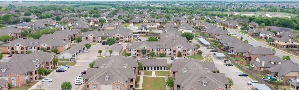
• Employment is expected to increase along I-35 and generally throughout the study area.
• Temple has a small but growing population of 55 and older, a declining population between 40 – 54, and a growing population of 25 – 39 years old.
• There is anticipated growth in goods and freight movement in the region.
• Future land use for Temple allocates 42% to industrial and 26% to rural/estate uses. Planning for freight movement and infrastructure that supports truck traffic will be critical to support this growth.
TEMPLE MOBILITY MASTER PLAN 49
5.2 Transportation Demand Modeling
5.2.1 Roadways
The KTMPO Model 2045 forecast year conditions were used to evaluate emerging and future trend scenarios. The future conditions roadway deficiencies analysis provides policymakers and the public with a better understanding of how the roadway network is currently performing.
Future Capacity Deficiencies
The following list identifies potential future capacity deficiencies expected to occur, despite currently planned improvements, based on the forecast model reported LOS. The streets and intersections below are described by their current design and forecasted impacts.
Roadways and Intersections
• Hartrick Bluff Road from FM 93 to City Limits
• SH 36 from Leon River to Loop 363
• SH 317 from Community Center Road to FM 439
• W. Adams Ave from Loop 363 to SH 317
• Old Waco Rd from S. Pea Ridge Rd to Riverside Trail
• S. Kegley Rd from W. Adams Ave to I-35
• SH 53 from Avenue H to FM 3117
• FM 439 from Sparta Rd to N. 10th Street
• FM 93 from I-35 to Old 95
• SH 95 from Orchard Ln to US 190
• Loop 363 from US 190 to I-35
• E. Young Avenue from N. 1st Street to Loop 363
• FM 436 from I-35 to Hartrick Bluff Rd
• W. Avenue T from W. 37th Street to S. 31st Street
• Scott Blvd from S. 57th Street to S. 51st Street
• Market Loop from Cottonwood Lane to S. 31st Street
• W. Avenue T @ N. 31st Street
• S. 57th Street @ Scott Blvd.
Figure 5.3 displays the LOS for the roadway network based on 2045 projections.
TEMPLE MOBILITY MASTER PLAN 50
It should be noted that commuters from the western areas of Bell County are channelized to the same three routes: SH 36, Adams Avenue, and I-35, based on the existing plus committed network. Additionally, locations where the roadway or intersection is shared with a TxDOT facility, coordination with that agency will need to occur as the City does not own the rightof-way.

TEMPLE MOBILITY MASTER PLAN 51
LOS A LOS B LOS C LOS D LOS E LOS F Level of Service 2045 0 0.75 1.5 3 miles
Figure 5.3: Temple Subarea Level of Service – 2045 Forecast Conditions
5.3 Future Operational Deficiencies Analysis
Using TransModeler software to forecast future conditions, a total of 207 intersections were analyzed for the future year. These projections indicate 24 total failing intersections in the AM with 11 LOS E and 13 LOS F gradings. Projections for the PM show 38 total failing intersections with 12 LOS E and 26 LOS F gradings. The failing areas in the future forecast are based on the assumption that the existing network and currently planned improvements are the only changes to the network. Table 5.1 and Table 5.2 show the top five failing intersections in each peak period.
5.3.1 Key Findings
• As expected, major roadways such as interstates and state highways are expected to see high levels of congestion and delay in the future.
• Many connections on the west side of town, near Loop 363 are forecasted as failing in 2045.
• Educational facilities within the City of Temple are expected to continue to be one of the largest activity generators in the community. Level of service around these institutions is typically congested, especially during peak hours.
• Industrial land uses will likely continue to expand in Temple, especially to the north. Impacts of the current delay and the freight network on future LOS will inform potential routing recommendations.
TEMPLE MOBILITY MASTER PLAN 52
INTERSECTION LOS DELAY (SEC/ VEH) Hilliard Rd, FM 2305 & Old Waco Rd F 363 31st St & I-35 Frontage F 253 Loop 363, Young Ave & FM 438 F 205 I-35 Frontage & Nugent Ave F 196 57th St & I-35 Frontage F 140
TABLE 5.1: FUTURE CONDITIONS – TOP 5 INTERSECTIONS WITH DEFICIENT/FAILING LOS FOR AM PEAK PERIOD
INTERSECTION LOS DELAY (SEC/ VEH) Hilliard Rd, FM 2305 & Old Waco Rd F 432 Central Ave & I-35 Frontage F 274 Industrial Blvd & Cearley Rd F 242 Loop 363, Young Ave & FM 438 F 236 US 190 / Loop 363 & 1st St Connector F 184
TABLE 5.2: FUTURE CONDITIONS – TOP 5 INTERSECTIONS WITH DEFICIENT/FAILING LOS FOR PM PEAK PERIOD
Source: TransModeler V6
5.4 Planned Multimodal Developments

5.4.1 Transit
The need for future transit options will continue to arise as the City looks for more mobility options. Technology innovations continue to change how the public views transit and its role in their personal mobility choices. The future will likely involve higher levels of telecommuting, more ride-hailing services such as Uber and Lyft, and additional bike/scooter share programs that will impact traditional transit ridership. These services currently operate throughout the city and are expected to continue to be a major part of the transportation network.
The HOP is part of the Hill Country Transit District (HCTD). The HCTD Service Provision Options Report completed in May of 2021 evaluated four future transit options for how HCTD could organize itself. Two scenarios were carried forward with implementation plans established by the HCTD Board. These scenarios focus on internal operations and not future routes or service operations that may impact the city of Temple. At the time of this planning process, plans for future improvement to the system were not publicly available.
5.4.2 Active Transportation
Analysis of the active transportation system using a grid of hexagons shows where walking and biking trips might likely happen. Hexagons were used because they provide a shape to which different input factors can be evenly attributed. If walking and biking facilities are comfortable and connected to key destinations in the areas identified in this analysis, it is likely that walking and biking trips may occur in those locations. This is not to say that walking and biking facilities should not be present outside of these higher demand areas, but that these areas may be a good starting place to examine current facilities and potentially make improvements.
Figure 5.4 shows areas with high concentrations of potential demand for walking and biking trips. The areas of higher demand are clustered near the central Temple area, especially along the gridded street network south of E. Adams Avenue. Areas with moderate demand are also scattered around the study area, especially where they are within proximity to parks or schools. There are pockets of moderate to high demand in areas west of I-35 and south of US-190 near Smith.
Planned and proposed bicycle facilities shown in Figure 5.5 were sourced from the 2020 Park and Trails Master Plan, Neighborhood Plans and Future Bicycle & Pedestrian Plan for the Region.

Low Low-Medium Medium-Low Medium Medium-High High-Medium High Potential Active Transportation Demand 0 0.5 1 2 miles
Figure 5.4: Likely Active Transportation Demand
Figure 5.5: Existing and Planned Bicycle Facilities
Existing and Planned Bicycle Facilities

Existing
Thoroughfare Connector Trail
Neighborhood Connector Trail
Greenway Trail
Planned
Thoroughfare Connector Trail
Neighborhood Connector Trail Greenway Trail
0 0.5 1 2 miles
Continuity between Park Trails and Planned On-Road Network
The planned connections for trails and on-street bicycle facilities do an excellent job of connecting the network, turning a set of park trails into part of the active transportation network (where it is feasible). Because these are planning level connections, there are yet to be precise plans for their location and design, specifically at intersections/crossings.
Parks and Trails Master Plan Recommendations

The City recently completed their Parks and Trails Master Plan that included a long-term vision for Temple’s parks and trails system. The plan focused on a 10-year horizon that prioritized implementation actions that respond incrementally to community needs. The plan is intended to be evaluated, adjusted and changed as needed. The following list highlights a few key park and trail mobility recommendations:
1. Expand Friar’s Creek Trail: 3–5-year initiation timeframe
2. Reconfigure 24th Street Bridge: 1–2-year initiation timeframe
3. Develop Georgetown Railroad to a Rails to Trails network: 1–2-, 3–5-year initiation timeframe
4. Develop a Regional Trail Network: Ongoing
5. Prioritize Trails: Various initiation timeframes
• Georgetown Railroad Trail #1
• Georgetown Railroad Trail #2
• Georgetown Railroad Trail #3
• Gateway Trail
• Hog Pen Creek Trail
• Veteran’s Trail
• Friar’s Creek Trail Extension
• Lake Terrace Trail
• Ferguson Trail
• FM 2305 Trail Extension
• Bird Creek Interceptor Trail
• Pepper Creek Trail Extension
• Leon River / Belton Trail
TEMPLE MOBILITY MASTER PLAN 56
5.4.3 Neighborhood Plans
The City has taken the initiative to complete individual neighborhood plans that identify community concerns, values, visions, and goals. The plans are intended to provide improved quality of life while increasing access to affordable housing. Each neighborhood plan helps inform the MMP by providing local context and identifying opportunities for specific project level recommendations. Additionally, future neighborhood plans should take into account the guidance from the MMP to provide consistency.
5.4.4 Freight and Aviation

Combining the positive economic outlook, potential for growth in freight-dependent industries, and the level of freight activity on the study area transportation system, the City of Temple shows opportunity for freight growth in the future. It is critical that the freight system is designed and maintained to support anticipated development and corresponding increases in freight traffic. Currently, the City does not have any plans in place to manage the freight network. The combination of industrial growth projections and identification of future LOS deficiencies on the freight network provide the City with valuable information resources for identifying and taking positive action steps to support economic sustainability.
The Airport Master Plan was developed in 2015, with short-, intermediate- and long-term planning extending to 2026. The plan focuses on recommended improvement on the actual site of the airport, including the design/construction of a Helicopter approach strip, hangers, and taxiways. Future connections and emerging technologies that would interface with the airport were not discussed in this plan. Connecting this resource with ground transportation through existing modes and emerging technologies can increase the utilization of this resource by residents and stakeholders.
TEMPLE MOBILITY MASTER PLAN 57
CHAPTER 6
SCENARIO ANALYSES

6. SCENARIO ANALYSES
A significant component of developing the MMP was analyzing multiple scenarios of priority, investment, benefit, and application of different modes of transportation to assess reasonable recommendations for the network. Scenario Planning visualizes outcomes across the community vision and spectrum of goals including transportation, economics, and social equity. The scenario analyses used performance measures to evaluate the community return on investment and the trade-offs of alternative transportation improvements, programs, and policies under a
Traffic Signal and Intersection Optimization
Optimize traffic signals and intersection performance by identifying improvements to intersection with an LOS of D or lower.
Scenario 2
Systemwide Roadway Improvements


Analyze and identify Improvements to roadway segments with an LOS of D or lower.
variety of possible future conditions or trends. Additional details of the scenario analyses can be found in Appendix C: Scenario Planning Technical Memorandum.
Each mode of transportation evaluated is dynamic and adheres to different internal and external influences. With those elements under consideration, each scenario was tailored to the mode being evaluated within Temple, leading to different analysis processes and measures.
Scenario 4
Transit Vision
Review of additional access and transit mode choice improvements to better serve communities. Focus on identifying route alternatives and approximate stop recommendations for underserved and socially vulnerable people.

Scenario 5
Active Transportation Improvements

Analyze how the addition of active transportation facilities and infrastructure benefits the character of the community and the quality of place as well as the health and well-being of the community.
Scenario 3
Regional Connectors
Add in improvements to major arterial roadways or higher to identify potential improvements to cross-town and regional trips.

Scenario 6
Emerging Technology & TSMO
Investigate potential impacts (curbside management, parking restrictions/ access, delivery) based on new policy or program recommendations for car sharing, bike sharing or scooter programs.

TEMPLE MOBILITY MASTER PLAN 59
Scenario 1
6.1 Scenario 1-3: Vehicular Transportation
Scenarios 1 – 3 are geared toward understanding impacts to traffic operations and congestion. Scenario 1 focused on poorly performing intersections in the study area. Scenario 2 reviewed deficiently performing roadway segments assuming recommendations from Scenario 1 were “implemented”. Scenario 3 built upon Scenario 1 and 2 networks to evaluate the performance of existing and proposed regional connections.
6.1.1 Scenario 1: Systemwide Traffic Signal and Intersection Optimization
The Temple region continues to grow, and that growth will ultimately have an impact on the performance of the roadway system. Scenario 1 optimizes traffic signals and intersection performance by identifying improvements to intersections with a deficient LOS of D or lower. The four phases of analysis demonstrated the perceived benefit to the region:
1. Population and Employment updates: Population and employment estimates were updated to reflect the most recent developments throughout the city and incorporated into the KTMPO model.
2. No-Build: Completed a model run for future 2045 conditions with no additional improvements to identify deficient intersections.
3. Signal Optimization: Completed a model run to optimize the timing and phasing of traffic signals in the study area and identified those still operating deficiently.
4. Standard Intersection Improvements: Implemented intersection improvements (such as approach lanes or turn bays) to the deficient traffic signals within the model and identified those still operating deficiently.
Scenario 1 identifies intersection deficiencies in the 2045 NoBuild and attempts to present conceptual solutions via signal optimization and standard intersection improvements. Table 6.1 shows the top five recommended intersection improvements (based on the impact), that were implemented in addition to the signal optimization in order to improve the intersection delay and LOS. Table 6.2 summarizes the performance of intersections within the study area for the No-Build conditions after signal optimization and intersection improvements.
TABLE
INTERSECTION RECOMMENDED IMPROVEMENT
Central Ave & 31st St Add right-turn lane northbound and convert thru to shared thru/right lane eastbound
Charter Oaks Dr & Midway Dr/Kegley Rd
Update northwest bound geometry to show dedicated left turn lane (updated to match current conditions). Add rightturn lane northeast bound and remove stop sign for northwest bound and southbound approaches
IH 35 NB Frontage & Hart Rd Add traffic signal
IH 35 SB Frontage & Hart Rd Add traffic signal
Loop 363/Young Ave & FM 438
Add left-turn lane northwest bound, add left-turn lane southbound, and add traffic signal
TEMPLE MOBILITY MASTER PLAN 60
6.1: SCENARIO 1 TOP 5 RECOMMENDED INTERSECTION IMPROVEMENTS AND IMPACT ON LOS
After the signal optimization, the number of deficient intersections was reduced by 36% in the AM and 29% in the PM. After including the intersection improvements, the number of deficient intersections was reduced by 69% in the AM, and by 49% in the PM. The results demonstrate the benefit of signal optimization and standard intersection improvements to the overall performance of the city’s intersections.
6.1.2 Scenario 2: Systemwide Roadway Improvements
Scenario 2 builds upon the Scenario 1 base network by providing additional recommendations to improve the performance of the remaining deficient intersections identified as part of Scenario 1. These recommendations concentrated on the deficient intersection approaches and roadway segments and sought to improve performance by introducing new turn bays, adding new turn lanes, adding capacity, or modifying lane assignments. Table 6.3 shows the top 5 highest impact improvements that were implemented as part of Scenario 2 to improve the intersection delay and LOS.
Hilliard Rd, FM 2305 & Old Waco Rd
Midway Dr, Charter Oak Dr & Kegley Rd
Add right-turn lane eastbound and southbound
Extend two-way left-turn lane on Kegley Rd from FM 2305 to Charter Oaks Drive and update functional class to minor arterial. Add traffic signal and change northbound lane assignment to left-turn lane and shared thru/right-turn lane
Old Hwy 95 & FM 93
Widen FM 93 from 2 to 4 lanes from FM 1741 to SH 95
Cearley Rd, SH 53 & Twin Oaks Dr Northbound lane assignment changed to left-turn lane and shared thru/right-turn lane
3rd St, Industrial Blvd & Young Ave
Add left-turn lane westbound
TEMPLE MOBILITY MASTER PLAN 61
LEVEL OF SERVICE NO-BUILD SIGNAL OPTIMIZATION INTERSECTION IMPROVEMENTS AM PM AM PM AM PM Total Deficient 45 55 29 39 14 29 Total Improved as Compared to No-Build - - 16 16 31 26 % Improvement as Compared to No-Build - - 36% 29% 69% 47%
TABLE 6.2: SCENARIO 1 2045 INTERSECTION PERFORMANCE IN TEMPLE REGION
INTERSECTION RECOMMENDED IMPROVEMENT
TABLE 6.3: SCENARIO 2 TOP 5 RECOMMENDED INTERSECTION AND SEGMENT IMPROVEMENTS
Delay and Percent Change in Delay for the scenarios compared to No-Build are based on the additional improvements. The total regional delay for Scenario 2 decreases by 4% from Scenario 1 and by 48% from the No-Build in the AM period, while PM reduces 4% beyond the improvement from Scenario 1 to a 52% decrease from the No-Build. As benefits are provided to the analyzed intersections and roadways, it will likely have an impact on other intersections upstream/downstream.

6.1.3 Scenario 3: Regional Connectors
The resulting Scenario 2 network informed Scenario 3, which analyzes major roadways to identify potential improvements to cross-town and regional trips. The regional connectors explored were roadways where additional capacity or connectivity would be beneficial to the performance of the regional transportation network. The following regional connectors were identified from the existing thoroughfare plan and identified gaps were analyzed:
• Highway 36 (Airport Road) - Evaluate the impact of providing additional capacity to a major regional arterial in a region of Temple that is projected to experience high levels of congestion in 2045
• Highway 317 - Evaluate the impact of providing additional capacity to a major regional arterial in a region of Temple that is projected to experience high levels of congestion in 2045
• Highway 95 – Evaluate the impact of providing additional capacity to a major regional arterial in a region of Temple that is projected to experience high levels of congestion in 2045
• Hickory Road – Evaluate the impact of providing an alternative parallel facility to 31st to alleviate congestion in this region
• 1st Street – Evaluate the impact of providing an alternative parallel facility to 31st to alleviate congestion in this region
• Western Outer Loop – Evaluate the impact of completing construction and upgrading the facilities to a 4 lane principal arterial to provide an alternate route to more urban centric roadways (Loop 363 and I-35)
• North Outer Loop – Evaluate the impact of completing construction and upgrading the facilities to a 4 lane principal arterial to provide an alternate route to more urban centric roadways (Loop 363 and I-35)
• Eastern Outer Loop – Evaluate the impact of implementing a new outer loop to support potential future development and to provide an alternative route to more urban centric roadways (Loop 363 and I-35)
In addition to the new regional connectors, interstate and expressway level roadways were reviewed to ensure the improvements planned along I-35, Loop 363 and US 190 were included within the scenario.
The impact of the large scale regional arterial connectors captures the benefit to the network at a regionwide level. The scenario explored a series of improvements and new construction of significant regional connectors in the study area. Table 6.4 displays the results of Scenario 3 when compared to the results of the NoBuild Scenario to understand how the full set of improvements benefit the study area.
TEMPLE MOBILITY MASTER PLAN 62
TABLE 6.4: SCENARIO 3 NO-BUILD AND 2045 LEVEL OF SERVICE
2045 NO-BUILD CONDITIONS 2045 SCENARIO 3
The following summarizes the improvements seen to the total regional delay (hours) of the Temple study area as reported by the Vehicle Miles Traveled (VMT) and Vehicle Hours Traveled (VHT) daily and per person. Annual weekday VHT reduced by 38% from the No-Build condition, while per person delay reduced by 47%.

TEMPLE MOBILITY MASTER PLAN 63
ROADWAY MILES % OF TOTAL ROADWAY MILES % OF TOTAL LOS A-C 342 67% 396 74% LOS D-F 172 33% 141 26% Total 514 100% 536 100%
%
Figure 6.1 and Figure 6.2 provide a high-level snapshot of LOS in the study area from the No-Build to the 2045 Scenario 3 condition.
Regional Delay
Changes


TEMPLE MOBILITY MASTER PLAN 64
Figure 6.1: Temple Subarea Level of Service –2045 No-Build Condition
LOS A & B LOS C & D LOS E & F Study Area KTMPO TAZ Level of Service 2045 LOS A & B LOS C & D LOS E & F Study Area KTMPO TAZ Level of Service 2045 0 1.25 2.5 5 miles 0 1.25 2.5 5 miles
Figure 6.2: Temple Subarea Level of Service –2045 Scenario 3
6.2 Scenario 4: Transit Vision
From the public feedback received, it is evident the Temple community is interested in more transit options. Scenario 4 looks for additional transit access and transit mode choice improvements. The scenario is intended to inform the recommendations of the Transit Vision Plan that will help decision makers understand the potential outcomes, cost, challenges, future needs, and a road map of potential transit options for the City.
A common theme from the public’s feedback was the need for a flexible transit option that meets their time and location needs. The introduction of Microtransit was a key element of this scenario analysis. Microtransit, or on-demand transit, is like a fixed route bus because passengers are asked to walk to meet a vehicle at a ‘virtual bus stop’ that may be up to ¼ or ½ of a mile from their requested location. However, it is different from a fixed route bus since there are no schedules or fixed routes. Instead, trips must start and end within specified zones that fill gaps in the bus network.
6.2.1 Alternatives Analysis
Three alternatives were explored in Scenario 4. Each provides the introduction of a bi-directional service, Microtransit through mobility zones, and includes differences between the candidate alternatives and the existing Temple transit service provided by routes 510 and 530. These alternatives were structured to determine the preferred combination of route and service concepts that will have the support of the community, City leadership, project partners, and City staff.
Alternative A modifies and expands the existing fixed routes 510 and 530. The alternative includes 1) replacing current loop routes with bi-directional service, 2) modifications to the existing routes for more streamlined and easier to use service, 3) more direct services to Temple College and the VA Hospital by the addition of route 520, and 4) service to the Industrial Park through a new 560 Industrial route. The alternative provides coverage similar to existing service with the expectation that those jobs that fall just outside of the stop locations would still be within a reasonable

walking distance and would still use the service. Figure 6.3 displays the proposed fixed route network of alternative A.
Alternative B uses the proposed fixed route services from Alternative A, minus Route 560. The alternative adds Mobility Zones in West Temple and North Temple to provide Microtransit services to these locations that adds potential for 12% additional coverage. Figure 6.4 displays the proposed route and mobility zones for Alternative B.
Alternative C also uses the proposed fixed route services from Alternative A, minus Route 560. However, the alternative includes the entire city as a mobility zone that adds potential for 100% coverage based on the on-demand service. Figure 6.5 displays the proposed route and mobility zones for Alternative C.
TEMPLE MOBILITY MASTER PLAN 65
Figure 6.3: Transit Alternative A

TEMPLE MOBILITY MASTER PLAN 66
0 0.75 1.5 3 miles 510 520 530 560 Industrial 200 Alternative A
Figure 6.4: Transit Alternative B


TEMPLE MOBILITY MASTER PLAN 67
510 520 530 200 West Mobility Zone North Mobility Zone Temple Transfer Station Zone
B 0 0.75 1.5 3 miles
Alternative
TEMPLE MOBILITY MASTER PLAN 68
510 520 530 200 Citywide Mobility Zone Temple Transfer Station Zone Alternative C 0 1 2 4 miles
Figure 6.5: Transit Alternative C
Upfront capital costs for Alternative A are highest of the three alternatives, since fixed-route vehicles are more expensive than Microtransit vehicles. However, because Alternative A requires the fewest vehicles overall, its yearly operating costs are lowest of the three alternatives. Conversely, Alternative C requires the most vehicles and operators, which would make it the most expensive to operate.
These draft alternatives are a culmination of the project team’s effort to develop a customized vision for transit that reflects the Temple community and is informed by both the technical analysis and the public input process. The alternatives and recommendations represent the mobility needs and wants of residents throughout the study area. Expanding the travel options for residents in Temple is an expansion of quality of life, which is imperative to any city that is experiencing growth.
Based on the scenario analysis the following recommendations are key to the development of the Transit Vision Plan.
• Increased Frequency – Through the addition of a new fixed route (Route 520) and modifications to the existing routes (to create more intuitive and bi-directional service), the City can be more strategic with transit resources and provide a route that operates every thirty minutes between the DT Transfer Station and Temple College (one of the most productive stops in the existing system).
• Intuitive Transit Design – Streamlined bi-directional service minimizes out-of-direction travel, reduces travel time, and fosters easy-to-use and easy-to-understand transit service.
• The Addition of Microtransit Service – The addition of Microtransit service expands and improves coverage across the entire network, giving riders from areas of the city that don’t currently have service the ability to commute into downtown more easily via the Temple Transfer Station Mobility Island.
• Microtransit ‘Mobility Island’ for Fixed Route Network
Connectivity – A mobility island serves as a way to connect Microtransit zones to the fixed route network. The Microtransit alternatives add a Mobility Island at the Temple Transfer Station.
6.3 Scenario 5: Active Transportation Improvements
Scenario 5 analyzes how the addition of active transportation facilities or infrastructure benefit the character of the community and the quality of place. The recommended improvements within the context examples aim to address challenges and opportunities presented by active transportation demand, level of stress, and the concerns and suggestions received through public input. The context level examples in this scenario provide a bank of recommendations for the City to reference a range and combination of available strategies. It also provides a guide to help identify opportunities to apply similar strategies in locations throughout the City. In this way, each context example provides a template for developing recommendations for the Active Transportation Plan.
Two locations, each with a different community context, were selected to provide examples of how a community could benefit from active transportation improvements. Context A prioritizes the connection of neighborhoods to important daily needs such as schools, public amenities, transit stations, parks, and major retail and employment areas. Context B focuses on example corridor improvements that provide connectivity across the City and integrate improvements to the on-street active transportation system with the use of off-street trails. This option also focuses on reducing significant barriers to crossing busy and wide streets by improving the design and frequency of crossing locations.
TEMPLE MOBILITY MASTER PLAN 69
6.3.1 Context A: Connecting People to Places – Meredith Dunbar Early Childhood School Example
Context A focuses on connecting the community to places they visit most often. While many people use personal vehicles to travel to and from their destinations, others may prefer, need, or desire to use other methods. The analysis provides a case study for connecting an activity center to its surrounding area by investing in new infrastructure or improving upon existing facilities near and around the location. The infrastructure analysis considered walk zones as ¼ mile from the activity center, while bike zones were considered as one mile from the activity center. Meredith Dunbar School was selected for this context review.
Within these boundaries, this example analyzes connections from the school to the surrounding neighborhoods and nearby amenities, employment, services, shopping, and recreational areas. Information gathered from the CSA, neighborhood plans, a stakeholder engagement meeting with the principal of the school, and public feedback were all considered when developing potential recommendations. Figure 6.6 presents a snapshot of preliminary recommendations and their impact on the system.

TEMPLE MOBILITY MASTER PLAN 70
Figure 6.6: Context A Example - Meredith Dunbar School
6.3.2 Context B: Key Corridors and Off-Street Connectivity – S. 25th Street Example
Efficient modes of transportation are built on a network with a strong backbone that provides quick, efficient, and convenient connections. For example, vehicular traffic could use an arterial as core east/west and north/south connectors. These types of streets are wide, have turning lanes in most locations, and prioritize travel along the corridor above the streets that intersect them. A transit system should have core routes that run at a higher frequency and provide convenient service in the highest demand locations. Similarly, the pedestrian and bicycle network should have key routes that supply comfortable, safe, and convenient connections without gaps or barriers where they are prioritized. Like Context A, this option analyzed infrastructure for walk zones at a ¼ mile from the corridor and bike zones at one mile from the corridor. South 25th Street in West Temple was selected as the example location for this context application of active transportation solutions.
The analysis of S. 25th Street focuses on closing gaps and identifying bicycle and pedestrian improvements that lead to seamless active travel along the corridor. Like context A, information gained from the CSA, neighborhood plans, stakeholder engagement and public feedback were all considered when developing potential recommendations. Figure 6.7 provides a snapshot of preliminary recommendations and their impact on the system.
The City has a variety of options to improve active transportation movement through several different contexts. The context reviews provided in this scenario showcase examples of potential projects the City can analyze for application at similar locations to close key gaps in the active transportation network. Relatively minor improvements such as new sidewalks, striping for crosswalks and bike lanes, and signage can have an impact on the network comparable to the impact of larger improvements such as intersection design enhancements, new hike and bike trails, and protected bike lanes. The analysis process and bank of recommendations from this scenario review will be carried into the development of the Active Transportation Plan.

TEMPLE MOBILITY MASTER PLAN 71
Figure 6.7: Context B Example - W. 25th Street
6.4 Scenario 6: Emerging Technology & TSMO
Scenario 6 considers the potential impacts on the transportation network, the City, and the region based on new emerging technologies and Transportation System Management and Operations (TSMO) policy or programs. As Temple and the surrounding area continue to grow, balancing the enhancement of safety and efficiently maintaining mobility will become more complex. With growth comes higher traffic volumes, a more complex mix of modes on the transportation system, more points of conflict, and a need for more sophisticated methods of evaluating and managing transportation needs.
Rapid development of a broad range of technologies in vehicle guidance, monitoring systems, automated data collection systems, artificial intelligence, traffic management software, communication systems, micro mobility services (car, bike or scooter sharing programs) and data management tools is creating new and exciting opportunities for how transportation services are supplied and managed. By examining the emerging technologies and advanced data collection and management methods that are on the horizon, the city can make decisions now that can help maximize the value of these technologies as they become available.
6.4.1 Existing Policy
This scenario identifies existing policies and other available programs regarding emerging technologies or TSMO strategies in place at the city or MPO level.
Interest in Emerging Technologies and TSMO was expressed in the City of Temple’s Comprehensive Plan 2020. Two of the stated principles of the Plan were to 1) Evaluate opportunities to invest in transportation demand management and smart city technologies to improve transportation efficiency, and 2) Proactively monitor predicted changes to the transportation system stemming from the onset of autonomous vehicle technologies.
Temple also recently implemented new initiatives to help with congestion, mobility and safety in the City. The first was the creation of a parking garage policy and the second was an initiative to look at additional midblock crossings that will provide a reduced walking distance for pedestrians when crossing busy roadways improving safety and mobility.
Consideration of Emerging Technologies and TSMO by KTMPO was evident in their Congestion Management Process (CMP) that states:
Technological efficiency improvement strategies utilize modern technology and computing capabilities to improve efficiency and operations in the existing transportation system. These strategies typically involve using sensors to collect and process data about traffic conditions. Information about traffic conditions can be directly presented to commuters in the form of electronic signage so that they can make travel decisions based on current conditions. The information can also be used to manipulate traffic operations based on current demands. Technological efficiency improvement strategies can effectively increase a transportation system’s capacity without requiring costly and time‐consuming construction.
TEMPLE MOBILITY MASTER PLAN 72
KTMPO’s CMP identifies a set of strategies that can be part of a toolbox for management of congestion including the following:
• Ramp Metering
• Traveler Information and Rerouting Systems:
• Electronic Commercial Vehicle Clearance and Tolls
• Automated Travel Time Measurement
• Route Information
• Traffic Signal Optimization

• Transit Signal Priority
• Demand-Responsive Signal System
• Transit Vehicle Tracking
• Motorist Assistance Patrols
• Strategies to Improve Accident Response and Clearance Time
• Parking Management
• Pedestrian Signals
• Bike Sharing System
6.4.2 Industry Best Practices
New technologies emerge quickly and can have a major impact of the transportation network. Although the City can’t plan specifically for new technologies that have yet to be developed or infiltrate the network, they can plan for the space they will potentially inhabit. Table 6.5 is list of emerging technologies, mobility solutions and advanced data management methods that the City should monitor and consider for future application.
TEMPLE MOBILITY MASTER PLAN 73
TABLE 6.5: BEST PRACTICES TOOLS FOR EMERGING TECHNOLOGIES, MOBILITY SOLUTIONS, AND DATA MANAGEMENT
INTERSECTION RECOMMENDED IMPROVEMENT
Sensors, Communications and Warnings
Weather and Flood Warning Systems
End-of-Queue Warning System
Speed Warning System
Pedestrian and Bicyclist Detection, Notification, and Warnings
Coordinated Traffic Management and Adaptive Signal Control
Vehicle Technologies
Expanded Regional Traffic Management Center (TMC)
Adaptive Signal Timing
Signal Infrastructure-to-Vehicle
Communications
Roadway Design, Infrastructure, and Maintenance to Support Safe Automated and Autonomous Vehicle Operations
Autonomous Shuttles
The analysis of emerging technologies and TSMO strategies in Temple and the surrounding area demonstrated that there is significant potential for these options. Discussion of the regional safety and mobility needs with key stakeholders from the study area revealed that there is strong support for costeffective strategies that can help optimize system performance through increased system management and operations. The discussion with key stakeholders also revealed an openness to consideration of innovative emerging technologies and methods as well as to greater collaboration among area agencies in the management and operations of the area’s transportation system. These findings and the appetite for inclusion of emerging technologies will be considered in the development of mobility recommendations for the study area.
Mobility Innovations
Ridesharing and Carpooling
Shared Micromobility
Curbside Management and ADA Accessibility
Advanced Data Collection and Data Management Methods
Use of “Big Data”
Real-time Traffic Data Capture by Signal System
Equipment
Advanced Video-based Data Collection
Automated Traffic Signal Performance Monitoring (ATSPM)
Asset Management and ITS Performance Monitoring Systems
Unmanned Aerial Vehicles (Drones) for Data Collection
TEMPLE MOBILITY MASTER PLAN 74
This page intentionally left blank
TEMPLE MOBILITY MASTER PLAN 75
CHAPTER 7
ACTIVE TRANSPORTATION PLAN

7. TEMPLE ACTIVE TRANSPORTATION PLAN


The Temple Active Transportation Plan facilitates the creation of a citywide approach to active transportation planning in the City of Temple while recognizing the characteristics of each neighborhood that make it unique. This Plan provides Temple staff and local planning partners with a guide and source of information to continue to grow a supportive culture of walking and biking, and to expand the City’s network of active transportation facilities.
7.1 What is Active Transportation?
Active transportation is walking or biking as a sustainable transportation option for daily commutes. While walking and bicycling are the typical modes that come to mind when discussing active transportation, it can also include any form of non-motorized, human-generated mode of transportation such as skateboarding, scooters, and rollerblading. Taking advantage of active forms of transportation can improve community health and wellness while reducing travel costs and expanding transportation networks to residents who do not own a vehicle.
In recent years, the City has experienced growth among both aging and younger populations. These age groups play a key factor in the City’s effort to provide more active transportation options for mobility. Walkable communities are a key ingredient in independent living and promoting physical activity for young and aging adults. For example, Safe routes to school increase the number of children walking and biking. Although most Texans rely on automobiles to get to work, run errands, and travel around town, more and more residents have been turning to active modes of transportation to complete these trips as communities invest in sidewalks, bike lanes, and hike & bike trails.
TEMPLE MOBILITY MASTER PLAN 77
7.2 The Active Vision
Temple’s vision for the active network is a safe, comfortable, inclusive, and equitable system of modern active transportation facilities that accommodates users of all ages and abilities and supports increased public health, excellent connectivity to transit and key destinations, and has simple and clear wayfinding. MMP goals and objectives associated with the Active Transportation Plan include the items shown in the following list.
Safety First:
• Reduce bike/ped fatal and serious injury crash rate
Choices:
• Reduce Single Occupancy Vehicle trips
• Increase bike/ped facility usage
Connections:
• Increase mode choices to residence or place of employment.
• Close gaps in the sidewalk/bicycle network
• Expand sidewalk/bicycle facility network

Prosperity:
• Incorporate elements of the Comprehensive Plan to identify strategies to reduce housing and transportation costs (Social Vulnerability Index).
Mobility:
• Achieve a reliable primary system.
Quality of Place:
• Design a context sensitive system that promotes neighborhood integrity and property values
• Protect the natural environment (air quality; water quality; wetlands and flood plain)
Fund and Implement:
• Provide development plans that support strategic initiatives that improve funding for transit and active transportation.
TEMPLE MOBILITY MASTER PLAN 78
7.3 Public and Stakeholder Feedback
As discussed in Chapter 3, public and stakeholder feedback was solicited at key points in the planning process and was accepted through an on-going basis through digital platforms. What we heard from the public and stakeholders:
• 47% of respondents identified barriers to walking and biking as primarily being a lack of sidewalks or bike lanes.
• Safe and connected pedestrian and bike facilities was the most significant mobility challenge in Temple, followed closely by transit options and accessibility and maintenance of existing roads.
• Expand bike trails and sidewalk network.
• Connect areas of the City, such as east Temple to the Industrial Park.
• Sidewalks needed throughout the City.
7.4 Key Principles
From this Vision stem three key principles used to develop the Active Transportation Plan. This coalition of principles prioritizes improving connectivity, accessibility, and community health while planning for a comprehensive active transportation system.
CONNECTIVITY
Increasing mobility across active transportation modes, while creating an integrated regional transportation network.
ACCESSIBILITY
Establishing a comprehensive system of transportation options and allowing users of all ages and abilities to access resources across the region
COMMUNITY HEALTH
Promoting active transportation modes that improve public health and support local economies.
TEMPLE MOBILITY MASTER PLAN 79
7.5 Who Are We Planning For?
Temple is a diverse, multicultural community made up of all ages. Using community feedback taken from the public engagement effort, user profiles were developed to showcase the wide array of typical user experiences that need to be considered when developing an Active Transportation Plan. This Plan is designed to provide benefits to everyone in the community. The following profiles provide examples of people you may find using the active transportation network.

A vital component in developing an active network for Temple is understanding that user profiles are simply a guide, and that user experience can vary from person to person. Trends identified in the data review and the community feedback provided insight into developing baseline recommendations. The City currently lacks the infrastructure to support a connected, ADA-compliant network. The community would like to see safe and seamless accessibility to all basic needs. The Active Transportation Plan aims to address these needs by providing a high-level review of the existing system, a toolbox for facility selection, project and policy recommendations, and context-level solutions that can carry forward into future project planning.
School Bus Users:

These users ride the bus to school. While the bus system works, they feel it could be more efficient and easier to access.
Walkers:
These users have lived in the community for many years. They like to walk to the local grocery store and use transit where available. They would like more benches and safer sidewalks.
Experienced Rider:

Bicycle riders who would like to explore the City and surrounding areas. They would like more regional connections to the hike and bike network.
Visitors:
Users who would like to explore the city more but are unfamiliar with the bicycle system. They would like more signage and wayfinding.

Families


These users are casual riders and families that walk their children to parks, schools, and other places of recreation and entertainment. They noticed the need for safer crossings at large intersections.
Retirees:
Recent retirees who enjoy walking around the neighborhood in the morning and evening. They would like more signage and shade on their walks.
Everyday Needs:
Individuals without access to vehicles. They would like more designated areas for walking, biking and last mile connections to transit.
TEMPLE MOBILITY MASTER PLAN 80
7.6 Existing Facilities

Active transportation infrastructure is an important component of a balanced transportation system that supports mobility. Pedestrian and bicycle-supportive infrastructure helps provide facilities that enable travelers to choose non-motorized travel throughout the study area and provides key accessibility connections to people with mobility challenges. Accessibility and connectivity for people who walk and bike or use other active transportation modes are primary goals of the Temple Comprehensive Plan 2020 and play a major role in the Temple MMP. Additional information on existing active transportation facilities can be found in Chapter 4 and the Appendices.
The City’s existing sidewalk network is predominantly in the central core of Temple east of I-35 to SH 363. The street network in this area is gridded with relatively short block lengths. A wellconnected street network can promote increased walking trips if paired with a sidewalk network in good condition.
Within the study area, there are nearly 40 miles of off-street hike & bike trails, including both paved and non-paved trails. Currently, there are limited designated on-street bicycle facilities, such as bike lanes or protected bike lanes, within the City.
Existing sidewalks and hike & bike trails within the study area are shown in Figure 7.2.
TEMPLE MOBILITY MASTER PLAN 81
TABLE 7.1: SIDEWALK COVERAGE IN THE CITY OF TEMPLE
Sidewalk Status Miles of Sidewalk % of Potential Sidewalk Existing Sidewalk 173 15.4% Missing Sidewalk 949 84.6% Total Potential Sidewalk 1,122 100%
Figure 7.1: Sidewalk Condition in the City of Temple
Figure 7.2: Existing Sidewalk and Trails
Existing Sidewalks and Trails

Very Good Good Fair Poor
Very poor No Condition
0 0.38 .75 1.5 miles
Existing Trails Thoroughfare Connector Trail Neighborhood Connector Trail Greenway Trail
Sidewalk Conditions Excellent
7.7 Integrating Parks and Trails Plan with Transportation System
It is important for the community to have safe, comfortable, and convenient access to the City’s parks network. The development of the active transportation recommendations proposed in this MMP are intended to compliment and build upon the locations of existing and proposed parks identified in the Parks and Trails Master Plan (PTMP), which was completed by the City in 2019.

The PTMP was an update to a 2014 document that led to a $27.6 million bond program that has already built many park and trail improvements throughout the City. The adoption of these plans highlights the commitment from City leaders to provide recreational opportunities for the community. Integrating the Parks and Trails Plan recommendations into the MMP is essential to the creation of a cohesive network.
The PTMP included recommended actions to improve Temple’s parks system in three major categories including Greenway Trails, Thoroughfare Connector Trails, Neighborhood Connector Trails. The following sections briefly describe each of these categories and provides a sample cross-section graphic.
7.7.1 Greenway Trails
Off-street greenways, often located in parks for recreation.
Figure 7.3 displays the typical cross section of a greenway trail as presented in the Parks and Trails Master Plan.

TEMPLE MOBILITY MASTER PLAN 83
Source: Parks & Trails Master Plan 2020
Figure 7.3: Greenway Trail Typical Cross Section
7.7.2 Thoroughfare Connector Trails
Corridors on the street intended to connect people from point A to point B. Figure 7.4 displays the typical cross section of a thoroughfare connector trail as presented in the Parks and Trails Master Plan.
7.7.4 Priority Trails
The following 13 trails were identified as priority trails:
1. Georgetown Railroad Trail #1
2. Georgetown Railroad Trail #2
3. Georgetown Railroad Trail #3
4. Gateway Trail
5. Hog Pen Creek Trail
6. Veteran’s Trail
7. Friar’s Creek Trail Extension
8. Lake Terrace Trail
9. Ferguson Trail
10. FM 2305 Trail Extension
11. Bird Creek Interceptor Trail
Source: Parks & Trails Master Plan 2020
7.7.3 Neighborhood Connector Trails
On-street and off-street trail connections. Figure 7.5 displays the typical cross section of a neighborhood connector trail as presented in the Parks and Trails Master Plan.


12. Pepper Creek Trail Extension
13. Leon River / Belton Trail
The recommendations from Parks and Trails Master Plan described above were incorporated into the development of the bicycle network and overall active transportation plan. Expanding on these recommendations will promote the connectivity of trails and greenbelt throughout the city, increasing options for regional connectivity and access for recreational, service, and daily needs.
Source: Parks & Trails Master Plan 2020
TEMPLE MOBILITY MASTER PLAN 84
Figure 7.4: Thoroughfare Connector Trails Typical Cross Section
Figure 7.5: Neighborhood Connector Trail Typical Cross Section
7.8 Neighborhood Plan Recommendations
The Active Transportation Plan incorporates recommendations outlined in the neighborhood plans being developed by the City under the ‘Love Where You Live Initiative’. These neighborhood plans include recommendations for pedestrian connectors and bicycle boulevards. Pedestrian connectors are corridors intended to act as feeder routes from the local streets to collectors and arterials. Key characteristics of these streets include:
• Improving sidewalks on both sides of the street
• Prioritizing sidewalks over planting strips
• Lighting for pedestrian use, rather than vehicle use
Bicycle boulevards are intended for streets with relatively low vehicle traffic and are designated by street markings and signage to help alert vehicles to the presence of bicyclist. Key characteristics of these streets include:
• No delineation of a designated bike lane
• Low vehicle traffic
• Clear and visible markings and signage
These recommendations are intended to complement the individual neighborhood plans and allow the City to use the plans to inform decisions on future project implementation. Figure 7.6 and Figure 7.7 provide an example of a pedestrian connector and bicycle boulevard cross-section from the Downtown Neighborhood Plan.


Source: City of Temple Downtown Neighborhood Plan
Source: City of Temple Downtown Neighborhood Plan
TEMPLE MOBILITY MASTER PLAN 85
Figure 7.7: Neighborhood Plan - Bicycle Boulevard Example
Figure 7.6: Neighborhood Plan - Pedestrian Connector Example
7.9 Network Development and Recommendations
Preliminary recommendations are provided in this section for advancement of the local active transportation network. Recommendations are based upon the needs discovered in the comprehensive system assessment, information learned from public engagement, previous planning efforts by KTMPO, Parks and Trails Master Plan, and the local neighborhood plans. This is not a comprehensive list of recommendations that is meant to satisfy all connections but a bank of improvements that were highlighted by analyzing demand and community feedback. The proposed routes and locations for projects are intended to provide the City with key corridors and connectivity to destinations. The City’s local knowledge and the tools provided in this Plan will be used to determine the most appropriate facilities.
7.9.1 Bicycle and Pedestrian Toolbox
A collection of bicycle and pedestrian design options are compiled in the following toolbox (Table 7.2) for the City to reference as a guide for development of active transportation improvements. Each mode of active transportation has different needs for design, context, and user. This range may necessitate that the City plan for a variety of different contexts that users may experience while using the network. The following sections outline options the City can explore when planning for bicycle and pedestrian improvements.

TEMPLE MOBILITY MASTER PLAN 86
Bicycle Boulevard:

route designated for bicycle travel through signage and/or markings
lane designated specifically for bicycle travel
bike lanes with physical separation from sidewalks and/or motor vehicle traffic


path designated for both bicycle and pedestrian travel
path without markings or dedicated signage
Designated space for people to walk or use wheelchairs

TEMPLE MOBILITY MASTER PLAN 87 Facility Facility Type Example Comfort Level Relative Cost Bicycle
Low $
A
Low $
On-street
High $$ Bicycle
Hike
Off-street
High $$$ Pedestrian
Off-street
Low $$$ Sidewalk
A
Bike Lane
Protected Bike Lane
and Pedestrian
and Bike Path
Side path
Low-High $$$
TABLE
7.2:
BICYCLE AND PEDESTRIAN TOOLBOX
Pedestrian
CROSSING FACILITIES
Signalized Intersection
Pedestrian Buttons
Allow pedestrians to request additional crossing time
High Visibility Crosswalk
Marked locations for pedestrian crossing at intersections
Mid-Block Crossing
Marked crossings between intersections
Crossing Island
Raised islands placed in the center of the roadway for pedestrian refuge during crossing

Rapid Flashing Beacon
Pedestrian actuated signals used in combination with crosswalks


Pedestrian Hybrid Beacon
$$$$
$$$$
A traffic control device actuated by pedestrians High $$$$$

TEMPLE MOBILITY MASTER PLAN 88 Facility
Example Comfort Level Relative Cost
Facility Type
Low
$$$
Low $$
Medium
$$$
Medium
Medium-High
Bicycle
CROSSING FACILITIES
Grade Separated Crossing
Elevated or below surface roadway crossings High $$$$$
Bike Pavement Markings
Marked locations for bicycle designated lanes
Bike Signal
Intersection crossing signal dedicated for bicyclist Medium $$$


TEMPLE MOBILITY MASTER PLAN 89
Example Comfort Level Relative Cost
Facility Facility Type
Low $$$
7.9.2 Bike Route or Shared-Use Path Network Map


The on-street and off-street bicycle network development for the City followed a four step process. The first step gathered input from the community on their daily needs for a bike network. The second step analyzed the data on existing levels of stress and future potential demand for bicycle use, utilizing Strava data. Third considered existing planning efforts from the Parks and Trails Master Plan, local neighborhood plans and the KTMPO Regional Multimodal Plan for incorporation. The information from the first three steps guided the final step of developing the base All Ages and Abilities (AAA) and Secondary Bicycle Network for the City. Figure 7.8 displays the process followed in developing the Temple MMP bicycle network recommendations.


TEMPLE MOBILITY MASTER PLAN 90
Step 1 - Public Feedback Step 2 - Level of Stress and Future Demand
3 -
Neighborhood Plans,
Planned Network
NAAA
Figure 7.8: Bicycle Network Four-Step Process
Step
Parks and Trails Plan,
KTMPO
Step 4 - AAA and Secondary
Bicycle Network


The All Ages and Abilities and secondary network will serve as a key baseline for an integrated active transportation network. The All Ages and Abilities network is intended to be the “backbone” of the system that facilitates longer travel options along corridors for all ages and abilities to use. This would require facilities that provide the comfort level for all users from a very young to old age, such as protected bike lanes or off-street hike and bike trails. The All Ages and Abilities network provides direct and convenient access for travelers that minimizes detours to connect local and city-wide destinations. The secondary networks will act more as a feeder into the All Ages and Abilities network and existing neighborhood streets. These facilities are intended to be geared more toward less-defined biking options such as signage, enforcement, and pavement striping.
Figure 7.9 highlights the different type of facilities appropriate for the proposed networks.
Facility Type Decision Tree
The decision tree shown in Figure 7.10 can be used to help identify the bicycle facility type recommended for the network. The proposed facility types are not intended to be the final recommendation for implementation. Rather, it is recommended the selection occur after further engineering evaluation of the available roadway widths, traffic speeds, and volumes, which is why the decision tree is associated with the functional classification from the Thoroughfare Plan. The contextual guidance decision tree is recommended to help the City determine the proposed All Ages and Abilities and secondary bicycle network.
TEMPLE MOBILITY MASTER PLAN 91
Figure 7.9: Bike Network Facility Examples
All Ages and Abilities (AAA)
Multi-use pathway
Bicycle Boulevard
Protected Bicycle Lane
Raised Cycle Track
Secondary (non-AAA)
On-street Bicycle Lane
Buffered Bicycle Lane
Shared Use Lanes (sharrows)
Local Street


TEMPLE MOBILITY MASTER PLAN 92
Figure 7.10: Decision Tree for the All Ages and Abilities and Secondary Bicycle Network
Proposed All Ages and Abilities and Secondary Network
The resulting bicycle system includes a proposed All Ages and Abilities and Secondary Bicycle Network that the city can build on as a guide to connected active transportation network. The Selection of All Ages and Abilities network is intended for roadways that will mostly serve as a high mobility function in the network, while the roadways for the secondary network are intended for roads with lower speeds within local neighborhoods. Identification of the All Ages and Abilities and secondary network is a step in the process that will lead to an integrated bicycle system for users of all ages and Temple neighborhoods.
It is recommended the selection of facility type is done collectively by using the bicycle toolbox and the decision tree in coordination with the roadway classification system. Figure 7.11 displays the five layers that make up the proposed bicycle network. Figure 7.12 displays the proposed All Ages and Abilities and secondary (Non-AAA) network for Temple. Table 7.3 details the associated proposed project list.

TEMPLE MOBILITY MASTER PLAN 93
Figure 7.11: Proposed Bicycle Network Development Layers
Figure 7.12: Proposed All Ages and Abilities and Secondary Bicycle Network
All Ages and Abilities and Secondary Bicycle Network
Proposed AAA Bike Network

Proposed Secondary Bike Network
0.25 Mile Walkshed
Parks
Existing Thoroughfare Connector Trail Neighborhood Connector Trail Greenway Trail
Planned
Thoroughfare Connector Trail Neighborhood Connector Trail Greenway Trail
0 0.5
1 2 miles
TABLE 7.3: ALL AGES AND ABILITIES AND SECONDARY BICYCLE NETWORK PROJECT LIST
TEMPLE MOBILITY MASTER PLAN 95 Map ID Network Roadway From To Estimated Length (ft) Comfort Level 1 AAA FM 2305 (Adams Ave) N. 50th St Belton Lake 70,000 Lowest 2 AAA Old Waco Rd FM 2305 North of S. Pea Ridge Road 21,000 Low 3 AAA Hilliard Rd FM 2305 Wendlands Farm Lake 25,000 Low 4 AAA SH 36 SH 317 I-35 35,000 Lowest 5 AAA Hog Pen Creek Trail FM 2305 Poison Oak 12,000 Highest 6 AAA S. Kegley Rd SH 36 I-35 20,000 Low 7 AAA Midway Dr I-35 S. 57th St. 10,000 Low 8 AAA Hickory Rd Midway Dr Stratford Dr 7,600 Medium 9 AAA S. 57th St West Avenue L Forest Trail 2,500 Low 10 AAA Georgetown RR Trail 1, 2, 3 Stonehaven Dr Leon River 26,500 Highest 11 AAA S. 5th St South of W Avenue U Canyon Creek Dr 7,500 Lowest 12 AAA W. Avenue L S. 57th St S. 8th St 13,500 Highest AAA Teague PL S. Martin Luther King Jr. Dr E. Marvin R Felder Dr 3,700 N/A AAA S. 2nd St E. Avenue L E. Avenue K 1,100 Highest 13 AAA South 25th St Adams Ave West Avenue T 9,200 Low 14 AAA SH 53 SH 290 I-35 6,500 Lowest 15 AAA 3rd St Adams Ave W. Avenue E 2,200 Low
TEMPLE MOBILITY MASTER PLAN 96 Map ID Network Roadway From To Estimated Length (ft) Comfort Level 16 AAA N. 7th St Mayborn Dr Adams Ave 8,000 High AAA Mayborn Dr N. 15th St N. 7th St 1,500 High AAA N. 15th St Industrial Boulevard Mayborn Dr 2,500 Low 17 AAA Martin Luther King Jr. Dr E. Nugent Ave Road 5 13,000 High AAA Martin Luther King Jr. Dr S. Martin Luther King Jr. Dr S. 24th St 3,500 Low 18 AAA East Avenue H S. Martin Luther King Jr. Dr Dodgen Loop 12,000 Lowest 19 AAA Lake Terrace Trail Prairie View Rd Connecticut Ave 6,000 Highest 20 Secondary Tarver Dr Old Waco Rd SH 317 10,000 Low 21 Secondary Hogan Rd Old Waco Rd SH 317 10,000 Medium 22 Secondary Poison Oak Rd Old Waco Rd SH 317 11,000 High 23 Secondary Pepper Creek Trail Ext FM 2305 S. Kegley Rd 5,500 Highest 24 Secondary Bird Creek Interceptor Trail Midway Dr Shallow Ford Rd 5,000 Highest 25 Secondary Stratford Dr Hickory Rd Waterbury Dr 3,000 Medium Secondary Waterbury Dr Stratford Dr Winchester Dr 1,100 Highest Secondary Winchester Dr Waterbury Dr S. 31st St 1,700 Low Secondary S. 31st St Winchester Dr Waters Dairy Rd 900 Lowest Secondary Waters Dairy Rd S. 31st St S. 5th St 5,500 Low
TEMPLE MOBILITY MASTER PLAN 97 Map ID Network Roadway From To Estimated Length (ft) Comfort Level 26 Secondary Cottonwood Ln Oakdale Ln Oakview Dr 1,800 Low Secondary Oakview Dr Cottonwood Ln Azalea Dr 1,000 Highest Secondary Azalea Dr Oakview Dr East of Lowes Dr 8,000 High 27 Secondary N. 23rd St Adams Ave W. Houston Ave 900 High Secondary W. Houston Ave N. 23rd St N. 31st St 500 High 28 Secondary W. Downs Ave N. 15th St N. 1st St 780 Highest Secondary N. 1st St W. Downs Ave E. Downs Ave 50 High Secondary E. Downs Ave N. 1st St E. Calhoun Ave 2,200 High 29 Secondary N. 1st St W. Adams W. Barton Ave 500 High Secondary W. Barton Ave N. 1st St Mid-block N. 1st and N. Main St 200 High Secondary Mid-block N. 1st and N. Main St W. Barton Ave W. Calhoun Ave 500 High Secondary W. Calhoun Ave Mid-block N. 1st and N. Main St N. 1st St 200 High Secondary N. 1st St W. Calhoun Ave W. Upshaw Ave 10,000 High 30 Secondary E. Nugent Ave N. 15th St N. 8th St 1,500 High 31 Secondary S. 24th St SH 53 Martin Luther King Jr. Dr 11,000 Medium 32 Secondary S. 30th St E. H Avenue Avenue N 3,000 Medium 33 Secondary Avenue N S. 30th St S. 24th St 900 High 34 Secondary S. 34th St E. H Avenue SH 53 3,400 Highest
TEMPLE MOBILITY MASTER PLAN 98 Map ID Network Roadway From To Estimated Length (ft) Comfort Level 35 Secondary Avenue Z 57th St S. 55th St 150 Highest Secondary S. 55th St W. Avenue Z Skyline Dr 120 Highest Secondary Skyline Dr/Everton Dr S. 55th St S. 31st St 2,100 Highest 36 Secondary East Loop Scott and White Blvd North Loop 350 N/A Secondary North Loop East Loop Inner Loop 100 N/A Secondary Inner Loop North Loop Utility Dr 250 N/A Secondary Utility Dr Inner Loop Emergency Dr 100 N/A Secondary Emergency Dr Utility Dr S. 31st St 600 N/A 37 Secondary S. 1st St SH 190 Fryers Creek 5,000 N/A 38 Secondary W. Avenue F S. 25th St S. Martin Luther King Jr Dr 2,000 Highest 39 Secondary S. 1st St W. Avenue D W. Avenue V 9,300 Lowest 40 AAA 31st St W. Houston Ave Georgetown Trail 40,000 Lowest 41 AAA Prairie View Rd Starlight Dr Hilliard Rd 15,000 High 42 AAA Canyon Creek Dr S. 31st St Old 95 Rd 12,900 Medium
7.9.3 Pedestrian Recommendations
The City is working to improve the pedestrian experience throughout the community and make Temple a better place to live by providing residents with options for comfortable walking. Pedestrian recommendations should follow a systemic approach where new projects or improvements can be coordinated in other initiatives such as street improvements, maintenance projects and program funding opportunities.
Prioritization of Improving Sidewalk Condition
Temple desires to improve the present sidewalk network to an ADA compliant network that connects the community. This effort promotes equality and accessibility for all ages while strengthening the basic unit of mobility within the overall transportation system. The existing sidewalk inventory was used to locate areas with the greatest need of improvement based on sidewalks in poor or very poor conditions and a set of criteria based on three tiers of priority Equity, Transit and Schools and Parks. Table 7.4 displays the criteria used.
1.
2.
3.
4.
Prioritization rankings are intended as a tool to allocate limited City sidewalk resources. If a sidewalk is ranked as a lower priority, it does not mean it is not a necessary component of a complete pedestrian network.
Pedestrian Connectors
It is recommended the City carry forward the integration of locations identified as pedestrian connectors in the neighborhood plans. These facilities will improve overall connectivity into the active transportation network and build on the existing sidewalk infrastructure. Consideration for these locations should be incorporated while prioritizing sidewalk improvements.
TEMPLE MOBILITY MASTER PLAN 99
Criteria Description Pts Equity 4
Poverty Block group’s average poverty is higher than the average for the whole city 1
Disability Block group’s average disability is higher than the average for the whole city 1
Minority Block group’s average minority population is higher than the average for the whole city 1
Property Values Parcel’s property value is less than the average property value for the whole city, but higher than $50,000 1 Transit 1 5. Transit ¼ mile from a transit stop 1 School and Parks 2 6. Schools ¼ mile from a school 1 7. Parks ¼ mile from a park 1
Figure 7.13 highlights the prioritization of sidewalks by the criteria established and the location of the pedestrian connectors.
TABLE 7.4: SIDEWALK PRIORITIZATION CRITERIA
Figure 7.13: Pedestrian Sidewalk Prioritization and Pedestrian Connectors

Pedestrian Connector High Priority Medium Priority Low Priority Parks Sidewalk Prioritization 0 0.38 .75 1.5 miles
Safe Routes to Schools
Promoting walking and biking to school through infrastructure improvements will provide a health benefit to the Temple community and promote active living for the younger generation during their everyday routine.
Safe Routes to School (SRTS) promotes safe, convenient, and fun travel options for children and families to bicycle to school and other destinations.

The SRTS programs are implemented at both local and regional levels. Locations were evaluated throughout the City to determine if they could benefit from these types of programs. This analysis reviewed sidewalk density within a ¼ mile walking distance (walkshed) of public schools in Temple. Locations with low sidewalk density were prioritized for future new or improved sidewalk projects. Figure 7.14 highlights the location of 22 public schools and their sidewalk density. Table 7.5 lists the potential future project locations for the City to consider for new or improved sidewalks.

TEMPLE MOBILITY MASTER PLAN 101
Figure 7.14: Safe Routes to School Sidewalk Density

0 0.38 .75 1.5 miles Sidewalk Streets Public School 0.25-Mile Walkshed Parks Safe Routes to School
TEMPLE MOBILITY MASTER PLAN 103 Map ID Sidewalk Density* Sidewalk Length/Road Length Sidewalks (ft) Street Length ft) Sidewalk Density 1 Cater Elementary School - 5,005 0.00 2 Temple High School - Sidewalks in Progress* - 2,477 0.00 3 Western Hills Elementary School - 4,931 0.00 4 Thornton Elementary 416 8,887 0.05 5 Charter Oak Elementary 859 7,822 0.11 6 Bonham Middle School 1,320 6,221 0.21 7 North Belton Middle School 1,484 6,264 0.24 8 Lamar Middle School 2,282 9,531 0.24 9 Tarver Elementary School 2,905 10,670 0.27 10 Raye Allen Elementary 1,039 3,682 0.28 11 Jefferson Elementary 4,121 13,782 0.30 12 Hector P Garcia Elementary 4,400 10,950 0.40 13 Pirtle Elementary School 1,166 2,898 0.40 14 Lake Belton High School 792 1,633 0.49 15 High Point Elementary 628 1,091 0.58 16 Edwards Academy Temple High School 6,868 10,886 0.63 17 Scott Elementary School 5,542 8,179 0.68 18 Lakewood Ranch Elementary 2,396 2,903 0.83 19 Travis Middle School 7,419 8,649 0.86 20 Meredith-Dunbar Elementary 10,976 10,984 1.00 21 Lake Belton Middle School 5,913 5,670 1.04 22 Kennedy-Powell Elementary School 3,378 3,018 1.12 Source: 2015 Community-wide Sidewalk Inventory; *Data may not reflect current conditions TABLE 7.5: TEMPLE PUBLIC SCHOOL SIDEWALK DENSITY
Sidewalk and Trail Project Review
A set of preliminary project locations within the study area resulted from the comprehensive system assessment and feedback from the public. These locations can be reviewed for future analysis and potential implementation. Locations were analyzed for highlevel recommendations based on national best practices. The demand analysis completed in the comprehensive system assessment highlighted areas in Temple where the demand scores are high and there are very few continuous North/South and East/West connections across the grid. The railroad is a significant barrier in this area and is likely forcing additional traffic to the few streets that go through. This reinforces the need for a balanced roadway approach to make sure active transportation modes are accommodated on the through streets. Table 7.6 and Table 7.7 displays planning level review of potential connections to close these gaps.
TEMPLE MOBILITY MASTER PLAN 104
Street From To Notes S 24th St Adams Ave/53 E Avenue N / MLK Railroad overpass to MLK/North 8th St. S MLK Jr Dr / N. 8th Street E Avenue E King Circle or Trail Crossing W Avenue F S MLK Jr Dr S 25th St S 25th St W H Ave W Avenue E Includes RR crossing W Avenue E S 25th St S 31 St Tie into trail or side path on S 31 St Stratford Dr Hickory Rd Waterford Park S 5th St Friars Creek Trail Temple College Pedestrian bridge over LP 363/US 190 W Adams Ave Hillard Rd N Kegley Rd Safety Improvements to upgrade from sidewalk to trail - with signage and crossings W Adams Ave Morgan’s Point Rd 317 Safety Improvements to upgrade from sidewalk to trail - with signage and crossings E. Avenue H MLK Henderson Rd Expand southwest and add bike lanes at the overpass to HB trail TABLE
7.6: ACTIVE TRANSPORTATION GAPS AND POTENTIAL CONNECTIONS
Location
Trail crossing across 1st Street at Temple College
Friar’s Creek Trail crossing across Canyon Creek Dr
Hickory Rd and Midway Dr
Active Transportation Advisory Committee
It’s recommended the City establish an Active Transportation Advisory Committee to help improve the coordination between city departments to implement active transportation projects. This will include recommending integration of bicycle and pedestrian infrastructure improvements while other city projects are being constructed. For example, during a street reconstruction project the advisory committee will coordinate the recommendations for the construction of sidewalks or possibly bike lanes during the street reconstruction project.
7.9.4 Active Transportation Policy Recommendations
External Outreach Program: Meet with local landowners, employers, and stakeholders to address Critical Site Connectivity Gaps
There is a gap in site connectivity from the roadway network and planned trail network to key employment centers and community facilities like the VA, Temple College and Baylor Scott and White Medical Center. The bicycle and pedestrian facilities stop at the edge, making the last hundred-foot connection to the 'front door' less comfortable for access. These segments are possibly private roadways. Nonetheless, multimodal connections are critical for successful connectivity. Coordination and collaboration between the City and these stakeholders will be necessary to reach the mobility plan goals.
Notes
Signalized, but could benefit from high visibility features, traffic calming or other safety improvements.
Marked, but could benefit from high visibility features.
Signalized, but could benefit from high visibility features.
Signage and Wayfinding Plan
While not a physical gap, it is also important to make sure there is not a knowledge gap of the on-street and off-street bicycle network and where it connects. It will be important for Temple to coordinate between Transportation and Parks and Recreation to create a signage and wayfinding system to clearly sign, mark, and map the linkages between the two systems for seamless integration.
Bicycle Riding on Sidewalks
The current Temple policy for bicycle riding on sidewalks defines prohibitions for certain types of conveyances in specified areas of the City.
Sec. 37-10. Riding on sidewalks. (a) It is unlawful for any person to ride or propel a bicycle or skate upon a skateboard upon any sidewalk in any area of the City zoned Central Area. (b) Subsection (a) does not apply to a sidewalk that is 8 feet or larger in width. (c) Any person riding or propelling a bicycle or skating upon a skateboard on any sidewalk in the City, must yield the right-of-way to any pedestrian on the sidewalk.
This language is currently being amended. It is recommended that the definition of what type of mobility is being ridden along sidewalks be expanded beyond bicycles to a broader category of micro-mobility devices. Section 37-10 (c) should be expanded so that all forms of sidewalk users yield to slower, more vulnerable users, not just specifying pedestrians, bicyclists, and individuals
TEMPLE MOBILITY MASTER PLAN 105
TABLE
CONNECTIONS
7.7: TRAIL CROSSING GAPS AND POTENTIAL
upon a skateboard. Finally, the issue of parking these devices should also be addressed to protect the pedestrian right-of-way and ADA accessibility.
Wide Sidewalk and Bike Paths Safety Evaluation
One of the biggest safety considerations for sidewalk riding is the access and egress of motor vehicles at driveways along the sidewalk combined with the higher traveling speed of the individual riding a bicycle or micro-mobility device along the sidewalk. Frequently, drivers are not conditioned to look for sidewalk users moving at a speed faster than a typical pedestrian. The sidewalk is often not engineered for faster speeds beyond a pedestrian. These potential conflict points need to be mitigated with limited driveway crossings, longer sightlines, and general engineering of the sidewalk for higher speed use. Areas within the city with wide sidewalks that are considered bicycle trails or paths frequently used by cyclists should be evaluated for safety.
Adopt Multi-Modal Typical Cross-Sections
Adopting an expanded set of typical cross-sections to include bicycle and sidewalk facilities can help make implementing bicycle and pedestrian facilities more routine. Example: Dallas Street Design Manual
Development Code Amendment: Future Development Active Transportation Connectivity
To ensure that the city ordinances support active transportation connectivity, the Unified Development Code should be revised to include requirements for adequate access from all neighborhoods to the proposed mobility plan network and promote the connectivity of the trail network to community destinations. Subdivisions should demonstrate connectivity for pedestrians and bicyclists to adjacent trail or bicycle facilities and between adjacent neighborhoods. Either as cul-de-sac easements or connected streets. Developments should provide an internal circulation plan that considers bicycle and pedestrian connectivity. Streets should be designed with appropriate bicycle and pedestrian accommodations to convey people throughout
the neighborhood
and
city. Example: Recommendation in the Fort Worth Active Transportation Plan
Active Transportation Design Implementation
Implementing active transportation facilities is only as successful as the perceived safety for people using the resulting facilities. To reach a broader community of potential active transportation travelers, these facilities must be designed for all ages and abilities. The All Ages & Abilities criteria is a national and international best practice that should be adopted for all bicycle facility design and network implementation; lesser accommodation should require additional justification.
Remove Parking Minimums
The removal of parking minimums can support an active transportation network by allowing developers to design less vehicle-dominated spaces and ultimately allow cities and places to be designed for people rather than cars where the market allows.
Support Speed Limit Reduction
Additionally, city staff and elected official support for reducing speed limits when a neighborhood requests a change or indicates a reduction in the neighborhood plan moves a city further towards a friendly environment for active transportation. Texas state law currently sets a neighborhood city street speed limit at 30 mph, unless otherwise marked and it is a significant expense for the city to individually assign each street they wish to be lowered. However, select streets may warrant a lower limit due to parks, schools or other amenities along that street, or because of neighborhood interest.
Design Standards
Developing citywide design standards that integrate active transportation facilities into the overall transportation network will be a key component of the success of the Active Transportation Plan. These design standards will be incorporated into municipal roadway design manuals or similar documents. Reference the
TEMPLE MOBILITY MASTER PLAN 106
proposed design standards and policy associated with bicycle facilities in Chapter 7: Thoroughfare Plan.
Safe Routes to School
This federal program was created to fund and support communities to provide safer walking and bike trips to and from school. The focus is on safe infrastructure development connecting schools to neighborhoods and transit. The program is funded at both a state and regional level, which encourages coordination among multiple agencies.
7.10 Active Transportation Plan Map
The resulting recommendations for the Active Transportation Plan can be viewed in Figure 7.15. Included are the proposed All Ages and Abilities and secondary bicycle network, the planned KTMPO hike and bike facilities, the neighborhood plan recommendations, and recommendations from the Parks and Trails Master Plan.
TEMPLE MOBILITY MASTER PLAN 107
Figure 7.15: Active Transportation Recommendation
All Ages and Abilities and Secondary Bicycle Network
Proposed AAA Bike Network

Proposed Secondary Bike Network
0.25 Mile Walkshed
Parks
High Priority Public School
Trails Existing
Thoroughfare Connector Trail
Neighborhood Connector Trail Greenway Trail
Trails Planned
Thoroughfare Connector Trail
Neighborhood Connector Trail Greenway Trail
Pedestrian Connector
NPD Bicycle Boulevard
Bike Lane
0 0.38 .75 1.5 miles
7.11 Action Plan
The action plan is meant to highlight next steps in implementing the recommendations presented in the Active Transportation Plan. The actions are highlighted in two sections which includes using the context solutions described in Chapter 6: Scenario Analysis to implement based on a context level approach, and an action summary table describing key actions from this Active Transportation Plan recommendations.
7.11.1 Context Solutions
Context can have a major impact on the design of a facility and the end user. Evaluating context can become a tedious process as the character and priorities of a community can differ between neighborhoods. To simplify this process, the MMP takes into consideration two overarching contexts that define the area and use them to inform active transportation improvements.
Context A: Connecting People to Place prioritizes the connection of neighborhoods to important daily needs such as schools, public amenities, transit stations, parks, and major retail & employment areas. Context A focuses on connecting the community to places they visit most often. While many people use personal vehicles to travel to and from their destinations, others may prefer, need, or desire to use other methods to reach their destination. Investment in this type of infrastructure yields many benefits to the community such as efficient transportation, improved air quality, and improved livability.
Context B: Key Corridors and Off-Street Connectivity focuses on corridor improvements that will provide connectivity across the City and will integrate improvements to the on-street system with the use of off-street trails. This context also focuses on reducing significant barriers to crossing busy and wide streets by improving the design and frequency of crossing locations.
Efficient modes of transportation are built on a network with a strong backbone that provides quick, efficient, and convenient connections. For example, vehicular traffic could use an arterial as core east/west and north/south connectors. These streets
are wide, have turning lanes in most locations, and prioritize travel along the corridor more than the streets intersecting them. A transit system might also have core routes running more frequently that provide convenient service in the highest demand locations. Similarly, the walking and biking network should contain key routes that provide comfortable, safe, and convenient connections throughout Temple.
Example case studies that applied this methodology for analyzing context solution-based recommendations can be found in Chapter 6: Scenario Analyses.
As the City works toward implementing future active transportation projects, the context solutions can be used to focus efforts and define priority levels of improvements.
7.11.2 Active Transportation Action Plan Summary Table
Table 7.8 provides a summary of the action plan for active transportation recommendations.
TEMPLE MOBILITY MASTER PLAN 109
Designate an All Ages and Abilities and Secondary (Non-AAA) Bicycle Network
Establish prioritization zones for new sidewalk construction, repair, or replacement
Coordinate with KTMPO and TxDOT on Safe Routes to School (SRTS) funding for new sidewalk constructions, repair, or replacement
Update City Policy to encourage Active Transportation in the City of Temple
Integrate Recommendations from the Parks and Trails Master Plan
Utilize the project recommendations provided to properly designate facilities based on the All Ages and Abilities and Secondary (Non-AAA) bicycle corridors.
Utilize the sidewalk prioritization locations provided to determine potential prioritization zones for coordinated efforts for new, repair, or replacement options.
Utilize the sidewalk density analysis provided to identify locations within City of Temple public schools for project selection.
Review policy recommendations for potential revisions or new policies promoting the use of active transportation
Carry forward recommendations from the plan and integrate project locations to connect to the parks and trails network
Establish an Active Transportation Advisory Committee
It’s recommended the City establish an Active Transportation Advisory Committee to help improve the coordination between city departments to implement active transportation projects.
TEMPLE MOBILITY MASTER PLAN 110
Summary MMP Goal Achieved
Action
TABLE
7.8: ACTIVE TRANSPORTATION ACTION PLAN
This page intentionally left blank
TEMPLE MOBILITY MASTER PLAN 111
CHAPTER 8 TRANSIT VISION PLAN

8. TRANSIT VISION PLAN
8.1 Transit Vision
Transit is a critical component of an effective and efficient multimodal transportation network. The only way to achieve this network is to create a plan for transit within Temple that is tailored to the needs, desires and characteristics of the City. The Transit Vision Plan provides updated transit routes and maps that define the desired elements of transit in the City, which needs to be a somewhat fluid plan that is flexible to changes in technology, demand, and financial constraints. The Vision recommends conceptual improvements to the transit system to enhance service delivery and support multimodal mobility.
8.1.1 Transit Goals and Objectives
Goals and Objectives were developed through discussion with city leaders, stakeholders, and the public. Five of the nine Goals include Objectives specific to promoting the use of transit within the City and evaluating its impact on the network. The goals and objectives that guide the Transit Vision Plan include the elements listed in the figures to the right.
Choices:
• Increase transit ridership to pre-COVID levels.
• Provide mobility improvements so drivers/ travelers can select their destination based on the quality of the destinations, not quality of their trip.
• Evaluate emerging technologies to consider modifications to the planning and design process to incorporate new modes, technology, and best practice.
Connections:
• Increase mode choices to residence or place of employment.
• Increase accessibility to transit.
Prosperity:
• Improve low income and minority transit.
Mobility:
• Improve frequency and coverage of transit service.
Fund and Implement:
• Provide development plans that support strategic initiatives that improve funding for transit and active transportation.
Quality of Place:
• Promote place-making through the development of context-sensitive complete streets design elements.
TEMPLE MOBILITY MASTER PLAN 113
8.1.2 Public and Stakeholder Feedback
As discussed in Chapter 3, public and stakeholder feedback was solicited at key points in the planning process and was accepted on an on-going basis through digital platforms. The following summarizes what we heard from the public and stakeholders related to transit:
• Improve availability of transit.
• Mediate the three barriers to using transit which were ranked almost equally: access, poor connections to desired destinations, and frequency of service.

• Evaluate the significant mobility challenges in Temple, which are safe and connected pedestrian and bike facilities, transit options, accessibility, and maintenance of existing roads.
• Consider micro-mobility options, such as bike rentals and point-to-point transportation.
• Consider a shuttle service to nearby restaurants for employees at Baylor Scott and White Hospitals.
The Transit Vision Plan described in the following sections is designed to achieve these stated goals and provide transit service delivery that meets community needs and expectations.
8.2 Existing Transit in Temple
Operating under the Hill Country Transit District, “The HOP” provides all fixed-route services in the study area. The HOP is a regional public transit system that started in the 1960s as a volunteer transit service and evolved to serve a nine-county area. Serving multiple cities through the largely rural service area, the HOP is a coverage-based, hub-and-spoke system.
Currently, there are two transfer stations, one in Killeen and one in Temple, that serve as the major ‘hubs’ and are connected in a linear pattern by two main routes. The HOP runs nine different fixed bus routes in the communities of Temple, Belton, Harker Heights, Killeen, and Copperas Cove. Two routes serve the City of Temple.

• Route 510 – VA Hospital/Temple College/Temple Mall/ Walmart
• Route 530 – Adams Ave/Temple HS/Social Security Office
Additional details on the existing transit conditions in Temple can be found in Chapter 4 and Appendix B: Comprehensive System Assessment Technical Memorandum.
A hub and spoke model of transit refers to the design of a route network. Typically, this type of network design centers around one or two central transit locations, from which all other routes disperse as “spokes” from the hub.
TEMPLE MOBILITY MASTER PLAN 114
8.3 Market Analysis
The Transit Market Analysis served as the foundation of the Transit Vision Plan and explored the existing conditions of fixed-route bus transit in the study area by examining each route’s ridership by stop, as well as by identifying how much of the underlying transit market is served by the routes.
Analyzing the existing transit service and the underlying transit market revealed the strengths of the existing system as well as gaps in service delivery. The analysis revealed areas in the City of Temple where there was an opportunity to use appropriate service strategies to better match the service delivery with the demand of the market being served.
8.3.1 Riders and Market Served
Understanding how the existing transit network functions were key to developing recommendations that would improve service for existing passengers and expand the system to make it more attractive for new passengers.
Figures 8.1 and Figure 8.2 show the results of the buffer analysis to assess the amount of transit market served by the existing fixedroute system.
The Figure 8.1 map shows that areas of both high population and employment are being served in locations outside of Temple, such as Belton, Harker Heights, and south Killeen. However, there are still many block groups in west Temple, north Temple, and southeast Temple that indicate medium-to-high levels of population and employment that are not currently served by the fixed-route transit system.
Figure 8.2 compares the levels of targeted transit riders (TTR) in each block group to the quarter-mile buffer generated around the existing transit stops. The map illustrates that there are block groups with high numbers of TTR around Temple. The largest concentration of these groups is located in southeast Temple, with a few spread across south Temple.
TEMPLE MOBILITY MASTER PLAN 115
8.1: Population and Employment Served by Transit

Population and Employment Served
High High
Quarter-Mile Stop Buffer Existing Hop Route Existing Hop Stops
Amtrak Stations
miles
FigurePopulation Employment Low 0 0.5 1 2
Figure 8.2: Target Transit Riders and Market Served


0 - 1,231 1,232 - 2,094 2,095 - 3,365 3,366 - 5,851 5,852 - 10,723 TARGETED TRANSIT RIDERS DENSITY 0 0.5 1 2 miles
8.4 Transit Service Improvement Recommendations
Recommendations for the Transit Vision are comprised of route alignment modifications, reductions, and additions, as well as the introduction of a new service delivery strategy known as microtransit. These recommendations contribute to creating a complete mobility profile for Temple that improves access and mobility at both the local and regional levels. The recommendations are a product of 1) the transit scenario analysis that evaluated three transit alternatives and addresses the key findings of the transit market analysis and 2) the input gathered from stakeholders and the public.
8.4.1 Guiding Principles
The Transit Vision Plan is based on five guiding principles specific to the City of Temple’s needs, namely: improving connectivity, eliminating route deviation, supporting route directness, designing efficient route spacing, and using bi-directional service. Designing route alignments and service delivery strategies to address these principles involves the synthesis of multiple data sets and resources. The data and resources listed below informed the customized recommendations to achieve the Transit Vision Plan:
• Public and stakeholder input
• Transit provider input


• Previous transit plan
• Transit market analysis
The following narrative provides an overview of the guiding principles that informed the route alignment, design, and service delivery strategies:
Connectivity
Connectivity is a function of the intersection between various transit routes or between the transit system and other transportation systems. Because fixed-route transit does not provide direct transportation between most people’s trip origins and destinations, users often need to use other forms of transportation (also known as first/last-mile transportation) to get to and from bus stops. Therefore, fixed-route transit systems must achieve efficient and effective connectivity to other transportation systems, to other transit networks or services, and between different routes within the same system. The alignment modifications are designed so that routes intersect with and connect to the Temple transfer station and other networks as directly as possible, particularly pedestrian and bicycle networks.
Route Deviation
When a route’s alignment is drawn to include minor deviations away from its most direct path to serve a single stop along with the deviation, the efficiency and travel time of that particular route are negatively impacted. These deviations reduce route productivity even further when the stops placed there have relatively low boarding activity (boardings + alightings). Where possible, the alternatives eliminate route deviations from fixed-route service. Parameters to serve as guidelines for evaluating deviations generally follow a rule of using a percentage of riders that would board along with the deviation and the time it takes for the deviation, and the number of passengers the deviation would negatively impact.
Route Directness
Like the concept of route deviations, route directness impacts the efficiency and travel time of a particular fixed route. Route directness refers to how immediately a route travels between stops that are adjacent to one another on the service schedule.

TEMPLE MOBILITY MASTER PLAN 118
Route Spacing
Route spacing is a measure of the distribution of two or more routes that come into proximity with one another. Consideration of fixed-route spacing was used to determine whether any service is being duplicated in any given area. In areas with high densities, duplication of service can increase bus frequencies and save time for passengers when one or more routes intersect or run along a shared segment. However, in a large service area where densities of population and employment are relatively low compared to other urban areas, the geographical duplication of service markets is more likely to occur when routes run parallel to each other on separate corridors. This results in a lost opportunity to distribute service coverage to a wider area, meaning that certain populations and destinations could go unserved or under-served. The alternatives propose routes spaced in a way that prevents different routes from running parallel and providing similar service to a corridor. More specifically, if two or more fixed routes have segments that run parallel to each other but do not overlap or intersect, these segments should be spaced at least a half-mile apart to help increase the geographical coverage of service.
Bi-Directional Service


One of the most critical concepts of this transit vision is the idea of bi-directional service. While a service relying on one circulator route provides good physical coverage and access to opportunities, it can force passengers to deal with significant out-of-direction travel and increased travel times. Because circulator routes operate on a loop, if the bus travels the loop in only one direction, some passengers will have to first travel away from their desired destination before the route eventually reaches their stop further along in the loop. This has compounding negative effects; not only does it increase travel time, but the perception of the inconvenient travel pattern may discourage some people from using transit. Figure 8.3 illustrates how a bi-directional route network can solve travel time issues that persist with a single-direction circulator route thereby making the routes more desirable to use.

Although a circulator service may initially help provide physical coverage and access, the service is limited in its ability to respond to changing demand and other potential context changes. For instance, if a specific section of a circulator route starts to experience higher ridership, the circulator can only increase frequency for the entire route, rather than simply increasing service on the section experiencing higher ridership. By contrast, if the area experiencing higher ridership was serviced by a bidirectional route network, the frequency can be increased along the in-demand section of the route (also illustrated in Figure 8.3). The bi-directional network allows service to be adaptive to transit demand and better allocate resources.

TEMPLE MOBILITY MASTER PLAN 119
Figure 8.3: Circulator vs. Bi-Directional Comparison
8.4.2 Microtransit Mobility Zones
In two of the alternatives analyzed, microtransit plays a key role as a service delivery tool. Microtransit, or on-demand transit, is like a fixed-route bus because passengers walk to meet a vehicle at a ‘virtual bus stop’ in mobility zones that may be up to ¼ or ½ of a mile from their requested location. However, it is different from a fixed route bus as there are no schedules or fixed routes. Instead, trips must start and end within specified zones that fill gaps in the bus network.
Passengers can book a trip using a smartphone application (“app”), a website, or through a call center. To book a ride, a passenger starts by indicating the number of passengers in their party and their desired pick-up and drop-off locations. Similar to the more common Uber and Lyft services, when booking a ride using the app, passengers will be able to see a map showing the geographic zone in which the service is offered. Requesting a trip beyond this zone is not possible, so passengers always know where the micro-transit service is available. Once the passenger submits a trip request, they are given an option that tells them when the vehicle will arrive and where to meet it. Typically, passengers must wait between 10 and 30 minutes for a trip, although this may vary depending on the level of demand and the number of vehicles available. Passengers can track the vehicle in real-time using the app. The passenger is provided with vehicle information—for example license plate, driver name, driver photo, and vehicle ID number. Passengers can usually cancel a ride at any time before pickup.
Once the vehicle arrives, the driver confirms the passenger’s details using the driver app. Passengers can pay using credit and debit cards, transit passes, cash, vouchers, and more. Most microtransit providers take care to include payment options for people without credit cards or bank accounts to ensure that the service is accessible to all. The passenger is then taken to their destination. Along the way, the vehicle will pick up and drop off other passengers heading in the same direction, but care is taken to avoid lengthy detours for passengers already on board. The passenger can track their progress using the app. After each trip, passengers may be automatically emailed a receipt or view it in the app. Passengers may also be able to provide real-time and post-trip feedback through the app.
Microtransit Examples
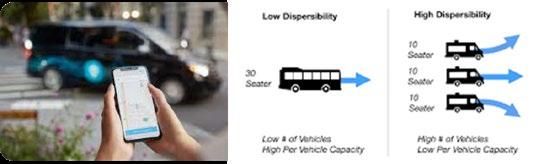
Microtransit has become more available throughout the US as locations without access to transit look for options to connect their residents. Not all locations are fit for a service such as microtransit but some examples have showcased benefits to the community.
L.A. Metro is one agency that recently expanded its microtransit services by adding three new service zones. The project is called Metro Micro with a cost of $1 per ride with fare adjustments being considered shortly. Their service has 5 zones for riders to choose from. More information on Metro Micro can be found at their website: https://micro.metro.net/

TEMPLE MOBILITY MASTER PLAN 120
Picture Source: https://micro.metro.net/
Low Dispersability High Dispersability 30 seater 10 seater 10 seater 10 seater Low % of Vehicles HighPerVehicleCapacity High%ofVehicles LowPerVehicleCapacity
Figure 8.4: Potential Microtransit Dispersibility
King County Metro near Seattle, WA extended their microtransit service for a second year after a pilot project tested the feasibility of the program. The on-demand service connects residents to and from transit community hubs in four service areas. Hours of operation are Monday-Saturday 5 a.m. to 1 a.m. and Sunday 6 a.m. to 12 a.m. Figure 8.5 displays the service zones provided. Additional information on the services provided can be found at their website: https://kingcounty.gov/depts/transportation/metro/travel-options/ on-demand/via-to-transit.aspx

The Central Ohio Transit Authority (COTA), near Columbus, Oh has also introduced microtransit to their community. The on-demand transports multiple customers who hail a transit vehicle at the nearest transit stop through the app. The service is provided in 4 areas throughout central Ohio including Grove City, Westerville, Northeast Columbus, and South Side areas. Hours of operation vary through each location served. Additional information on the program can be found at the website: https://cota.com/services/cota-plus/

The City should consider the following if implementing a pilot microtransit program:
• Pickup window – The City should set the amount of time a pick-up can occur before or after the scheduled pickup time at +/- 20 minutes during the pilot and then strive to lower it to 15 minutes once service is established.
• Negotiated trip window – The City should set the time to +/60 minutes as the amount of time a dispatcher can schedule a trip before or after the requested pickup time.
• Detour allowance - The time or distance allowed during a trip to pick up additional passengers should be set to achieve an average ride time of approximately 20-30 minutes or better per passenger, which would be comparable to the average ride time of the current fixed-route service in Temple.
TEMPLE MOBILITY MASTER PLAN 121
Picture Source: https://cota.com/services/cota-plus/
Figure 8.5: King County Microtransit Zones
Source: King County Metro
8.4.3 Alternatives Analysis
The alternatives analysis described in this section provides an overview of the candidate service alternatives developed by the project team. The benefits and tradeoffs between each alternative are described. Each alternative includes a map and performance metrics. These alternatives were set up in a manner that allowed the project team to isolate the strengths and eliminate the weaknesses of each and determine the preferred combination of route and service concepts that would have the support of the community, City leadership, project partners, and City staff. The other effective feature of this process is that several of these concepts can be implemented in a sustainable and phased process.
The performance metrics used for this analysis are based on the Comprehensive System Assessment – Existing Conditions analysis. The percentages are based on the total percentages of the study area. While each of these alternatives adds a new route there are also tradeoffs associated with achieving more intuitive routing, bidirectional service, and more frequency. Some coverage service is proposed to be reduced and this impacts the percentage of the population and employment covered under the quarter-mile buffer. An example of this can be seen in Alternative A where service was modified around the Baylor Scott and White Hospital. This hospital accounts for 10,189 jobs and is the biggest job center in Temple under Alternative A, less of the block group is covered under the quarter-mile buffer than under the existing service but the proposed service would be enhanced under this plan and the expectation would be that those jobs that fall just outside of the buffer would still be within a reasonable walking distance and would still use the service.
The performance metrics are defined as:
• Targeted Transit Riders - The demographic groups for this metric are more likely to create demand for transit service and include:
• Population with disabilities
• Population with limited English proficiency
• Population of minorities
• Population aged 65 and older
• Population aged 17 or younger
• Population in poverty
• Population – any population that falls within a quarter-mile buffer around the proposed transit line. The quarter-mile buffer represents the assumed maximum distance that most people would be willing to travel by foot or assistive mobility device to reach a transit system access point (bus stop or transfer station).
• Employment - any employment that falls within a quartermile buffer around the proposed transit line, which represents the assumed maximum distance that most people would be willing to travel by foot or assistive mobility device to reach a transit system access point (bus stop or transfer station).
The alternatives below show the differences between the candidate alternatives and the existing Temple transit service provided by routes 510 and 530. For this effort, route 200 is shown as a dashed line so the regional connectivity can be observed, but the route is not included in the metrics analysis because it has regional connections outside of Temple. Microtransit coverage benefits are stated separately from those of the fixed routes because of the different nature of the service and to allow for direct comparison between the alternatives.
TEMPLE MOBILITY MASTER PLAN 122
8.4.4 Alternative A
Alternative A builds on the existing fixed-route service offered by the HOP by adding 2 routes, enhancing the route for better frequency, and implementing bi-directional service.
Key Route Descriptions:
• Transition to bi-directional.
• 510 – The proposed 510 route was modified to run in a more intuitive and direct route between the Temple Transfer Station and south Temple. This route will provide a faster trip between the transfer station and key destinations along the route such as the Baylor Scott & White Medical Center and the Temple Mall.
• 520 – The proposed 520 is a modified version of the north section of the existing 510 route. This route would now be a more frequent route with a 30-minute headway and provide direct bi-directional service between the Temple Transfer Station and the VA Hospital and Temple College.
• 530 – The proposed 530 route was modified to provide a more direct, intuitive, and bi-directional service between east and west Temple.
• 560 Industrial Route – The addition of the proposed 560 route will provide service to the industrial park introducing opportunities for more access to jobs.
TEMPLE MOBILITY MASTER PLAN 123
Figure 8.6 provides an overview of the existing routes compared to Alternative A.
Figure 8.6: Alternative A Overview

TEMPLE MOBILITY MASTER PLAN 124
8.4.5 Alternative B
Alternative B builds on the recommendations from Alternative A, minus the addition of Route 560. This alternative introduces the option for Microtransit Mobility Zones in North and West Temple.
Key Route/Service Descriptions:
• One Mobility Zone that offers on-demand microtransit options to West Temple to provide transit options to the residents in the areas where new development is occurring.
• One Mobility Zone that offers on-demand microtransit options to North Temple where previous access to the existing service was not available and provides access to the nearby transfer center and Industrial Park. This option will allow for a service frequency that does not have to plan around the shift times of the employers in the Industrial Park.
• Transition to bi-directional.
• 510 – The proposed 510 route was modified to run in a more intuitive and direct route between the Temple Transfer Station and south Temple. This route will provide a faster trip between the transfer station and key destinations along the route such as the Baylor Scott & White Medical Center and the Temple Mall.
• 520 – The proposed 520 is a modified version of the north section of the existing 510 route. This route would now be a more frequent route with a 30-minute headway and provide direct bi-directional service between the Temple Transfer Station and the VA Hospital and Temple College.
• 530 – The proposed 530 route was modified to provide a more direct, intuitive, and bi-directional service between east and west temple.
TEMPLE MOBILITY MASTER PLAN 125
Figure 8.7 provides an overview of the existing routes compared to Alternative B.

TEMPLE MOBILITY MASTER PLAN 126
Figure 8.7: Alternative B Overview
8.4.6 Alternative C
Alternative C builds on the recommendations from Alternative A, minus the addition of Route 560. This alternative introduces the option for Microtransit Mobility Zones for all of Temple.
Key Route/Service Descriptions
• One Mobility Zone that offers on-demand Microtransit options to all of Temple. This will allow for a resident in every part of town to select on-demand as an option to connect into transit or to their destination of choice.
• Transition to bi-directional.
• 510 – The proposed 510 route was modified to run in a more intuitive and direct route between the Temple Transfer Station and south Temple. This route will provide a faster trip between the transfer station and key destinations along the route such as the Baylor Scott & White Medical Center and the Temple Mall.
• 520 – The proposed 520 is a modified version of the north section of the existing 510 route. This route would now be a more frequent route with a 30-minute headway and provide direct bi-directional service between the Temple Transfer Station and the VA Hospital and Temple College.
• 530 – The proposed 530 route was modified to provide a more direct, intuitive, and bi-directional service between east and west Temple.
TEMPLE MOBILITY MASTER PLAN 127
Figure 8.8 provides an overview of the existing routes compared to Alternative C.

TEMPLE MOBILITY MASTER PLAN 128
Figure 8.8: Alternative C Overview
8.4.7 Alternatives Planning Level Cost Estimation
For each alternative, capital and operating costs were estimated. Capital costs are one-time upfront costs comprised of the cost of new buses and for this effort, $435,000 per fixed-route vehicle and $130,000 per microtransit vehicle are used as a standard cost per vehicle. Every fixed-route requires one vehicle, the North and West Mobility Zones of Alternative B require one vehicle each, and the Citywide Mobility Zone requires three vehicles. Operating costs, which are estimated across one year, involve the number of hours and days of operation and the current cost of operating a vehicle, provided by the HOP as $100.00/hour for a fixed-route vehicle and an industry standard of $55.00/hour for a microtransit vehicle. The costs estimates were extracted to be specific to the operations in the City and not directly correlated to the operations of HOP routes in their entirety which include other service areas. Table 8.1 provides the variables used for developing cost estimates for each alternative.
Table 8.2 shows that upfront capital costs for Alternative A are the highest of the three alternatives, since fixed-route vehicles are more expensive than microtransit vehicles, and this alternative requires the most fixed-route vehicles. However, because Alternative A requires the fewest vehicles overall, its yearly operating costs are the lowest of the three alternatives. Conversely, Alternative C requires the most vehicles and operators, which makes it the most expensive to operate.
TEMPLE MOBILITY MASTER PLAN 129
Variables Span of Service in Hours (5:25am - 6:45pm) 13.33 hours Weekday days of service 5 days Saturday days of service 1 day Number of holidays 12 days Annual weekdays of service (365 minus weekends and holidays) 249 days Annual Saturdays of service 52 days Fixed-Route Operating Cost per Hour $100.00 Fixed-Route Vehicle Cost $435,000 Microtransit Operating Cost per Hour $55.00 Microtransit Vehicle Cost $130,000
TABLE 8.1: VARIABLES FOR COST ASSUMPTIONS
8.4.8 Partnerships/Funding
The City needs to determine how transit will be funded and who is going to operate the system. This Transit Vision Plan is adaptable and identifies the key strategies and parameters for implementation and ongoing operations.
Contract Revenue
Contracts are funding agreements between the transit agency and another organization to provide transportation services. The organization, which may be a local government, a non-profit organization, an employer, or a university, pay the provider on behalf of their clients. This means that the contract revenue is not considered fare revenue, and therefore does not offset federal funding. Contracts include revenues from regularly provided transit services, which differentiate this type of revenue from charter service.
Federal Programs that Support Public Transportation
Many federal programs provide funding for public transportation and transit specifically. This includes competitive programs such as the Rebuilding American Infrastructure with Sustainability and Equity (RAISE) grant, the Urbanized Area Formula Funding program (49 U.S.C. 5307), and discretionary grants such as the Grants for Buses and Bus Facilities program (49 U.S.C. 5339).
Urbanized Area Funding 5307
The Urbanized Area Funding 5307 Grant makes federal resources available to urbanized areas (population of 50,000 or more) for transit capital and operating assistance in urbanized areas and transportation-related planning. These funds are apportioned on a formula basis calculated based on the urbanized area population and transit service levels. Key eligible transit activities under this program include planning, engineering, design, and evaluation of transit projects and other technical transportationrelated studies; capital investments in bus-related activities, and computer hardware and software. Section 5307 formula funds for the Killeen-Temple urbanized area are dedicated to the HOP under current service agreements.

TEMPLE MOBILITY MASTER PLAN 130 Alternative A 4 Fixed Routes No Mobility Zones 4 Vehicles Alternative B 3 Fixed Routes 2 Mobility Zones 5 Vehicles Alternative B 3 Fixed Routes 2 Mobility Zones 5 Vehicles Capital Cost $1,740,000 $1,565,000 $1,695,000 Yearly Operating Cost $1,604,932 $1,645,055 $1,865,733
TABLE 8.2: CAPITAL AND OPERATING COSTS BY ALTERNATIVE
Figure 8.9: Capital and Operating Cost by Alternative
Grants for Buses and Bus Facilities 5339
The 5339 grant provides federal resources to States and designated recipients to replace, rehab, and purchase buses and related equipment, and to construct bus-related facilities. Eligible recipients of this grant include recipients that operate fixed-route bus services or that allocate funding to entities that operate the fixed-route service. Additional eligible capital projects include replacing, rehabilitation, or purchasing vans.
RAISE Grant
The Rebuilding American Infrastructure with Sustainability and Equity (RAISE) program allows project sponsors at the State and local levels to invest in road, rail, transit, and port projects. The grant can provide capital funding directly to any public entity including municipalities. Projects are evaluated on several criteria including safety, environmental sustainability, quality of life, economic competitiveness and opportunity, state of good repair, partnership, and innovation. Recent transit awards include dedicated bus lanes in Baltimore and a rail-to-trail project in Arkansas.
Public/Private Partnerships
A public-private partnership is an arrangement between a public or government agency and a private entity that (typically) shifts funding from a sole source of governmental aid (grants) to a diverse approach that also uses private funding. It will also typically place more reliance on the private entity to deliver or operate the project. However, the agreement can extend to multiple aspects including the funding, financing, planning, design, construction, operation, and maintenance of a transportation facility. For example, there are possible public-private partnership opportunities with companies in the Industrial Park that the City can explore when considering transit services to and from the service area.
8.5 Implementation Steps
The recommendations of this Transit Vision Plan will be implemented in phases based on the input of technical analyses, regional coordination efforts, and public and staff input. This implementation section outlines the costs and recommendations for each phase. This phased approach will work in tandem with the MMP to implement the recommendations successfully and sustainably for quality transit throughout the service area that helps contribute to the development of a complete mobility profile. The implementation plan is separated into two phases:
• Phase 1 – Short Term Improvements (1 to 2 years): Fixed route realignment that focuses on building a foundational base for the transit network which connects the community with more frequent, bi-directional, and intuitive service.
• Phase 2 – Long Term Improvements (Years 2 to 5): Implementation of Microtransit service, an additional fixed route, and increased frequency on more fixed-route service.
These phases aim to help disperse costs and prioritize sustainable, phased changes. Within the phases, there are recommendations for prioritizing the implementation of various steps.
8.5.1 Phase 1 – Short Term Improvements
Implement the three routes that serve as the core foundation for each of the proposed alternatives. These include routes 510, 520, and 530.
Phase 1
(Realignment
Total Annual Operating Cost - Weekdays $995,751
Total Annual Operating CostSaturdays $207,948
Total Annual Operating Cost $1,203,699
Total Capital Cost $1,305,000
TEMPLE MOBILITY MASTER PLAN 131
of 3 Fixed Routes)TABLE 8.3: PHASE 1 COST ESTIMATES
8.5.2 Phase 2 – Long Term Improvements
Phase
Once the City has the core fixed-route transit network in place and has analyzed ridership data for some time the next step would be to introduce microtransit as a new mobility option. The first microtransit zone should be introduced and marketed as a pilot program. The first zone to be established should be the West Mobility Zone from Alternative B.
Once the pilot program has been in place for a year and the City has evaluated performance metrics the next step would be to expand or end the program. If it is determined to be a success, then the next phase would be to introduce a second mobility zone in the north industrial area from Alternative B.
If the mobility zones continue to serve as a viable transportation alternative, then the next phase would be to implement the citywide mobility zone from Alternative C.
TEMPLE MOBILITY MASTER PLAN 132
2A
Phase 2A (West Mobility Zone) Total Annual Operating Cost - Weekdays $182,554 Total Annual Operating CostSaturdays $38,124 Total Annual Operating Cost $220,678 Total Capital Cost $130,000
2B
Phase
2B
Phase
(North Mobility Zone)
Saturdays
2C
Total Annual Operating Cost - Weekdays $182,554 Total Annual Operating Cost -
$38,124 Total Annual Operating Cost $220,678 Total Capital Cost $130 ,000 Phase
2C
Phase
(Citywide Mobility Zone)
Saturdays
Total Annual Operating Cost - Weekdays $547,663 Total Annual Operating Cost -
$114,371
Total Annual Operating Cost $662,034
Total Capital Cost $390,000
TABLE 8.4: PHASE 2A COST ESTIMATES
TABLE 8.6: PHASE 2C COST ESTIMATES
TABLE 8.5: PHASE 2B COST ESTIMATES
Phase 2D
Implement the fixed-route industrial zone.
TABLE
Phase 2D
(Industrial Route)
8.5.3 Alternatives A, B, and C Cost Estimates
Total
Phase 2E
Systematically begin adding buses to fixed routes based on their performance metrics (i.e., the route with the most ridership) to provide increased frequency. Begin with routes 510 and 530 which would allow them to operate at a 30-minute headway like route 520.
TABLE
Table 8.8 through Table 8.10 provide the cost breakdown of each Alternative based on the phasing approach. Alternative A (3
TABLE
Phase
West Mobility Zone, North Mobility Zone)
TEMPLE MOBILITY MASTER PLAN 133
$331,917
Annual Operating Cost - Weekdays
Saturdays $69,316
Annual Operating Cost $401,233 Total Capital Cost $435,000
Total Annual Operating Cost -
Total
Cumulative
Capital Cost
Phase 1 $1,203,699 $1,305,000 Phase 2D $1,604,932 $1,740,000
Routes,
Fixed Routes, Industrial Route) Phase
Operating Cost
to Date
Alternative B (3 Fixed
Cumulative Operating
Capital Cost to Date Phase 1 $1,203,699 $1,305,000 Phase 2A $1,424,377 $1,435,000 Phase 2B $1,645,055 $1,565,000
C (3 Fixed Routes, Citywide Mobility Zone)
Cumulative Operating Cost Capital Cost to Date Phase 1 $1,203,699 $1,305,000 Phase 2C $1,865,733 $1,695,000
Cost
Alternative
Phase
8.7: PHASE 2D COST ESTIMATES
8.8: ALTERNATIVE A COST ESTIMATES
8.9: ALTERNATIVE B COST ESTIMATES
TABLE 8.10: ALTERNATIVE C COST ESTIMATES
8.5.4 Key Components/Takeaways for this Transit Vision Plan
• Increased Frequency – Through the addition of a new fixed-route (Route 520) and modifications to the existing routes, to create a more intuitive and bi-directional service, the City can be more strategic with transit resources and provide a route that operates every thirty minutes between the DT Transfer Station and Temple College (one of the most productive steps in the existing system).
• Intuitive Transit Design – Streamlined bi-directional service minimizes out-of-direction travel, reduces travel time, and fosters easy-to-use and easy-to-understand transit service.
• The Addition of Microtransit Service – The addition of microtransit service expands and improves coverage across the entire network, giving riders from areas of the city that don’t currently have service the ability to commute downtown more easily via the Temple Transfer Station Mobility Island. Thresholds would need to be set by the City as to when a passenger would be connected to a fixed route versus completing a trip solely using microtransit. Generally, if a passenger is within walking distance (i.e. ¼ - ½ mile) of a bus stop the service would force a passenger to take a fixed route. If the passenger was outside of that threshold, then microtransit would assign them to a trip.
• Microtransit ‘Mobility Island’ for Fixed Route Network
Connectivity – A mobility island serves as a way to connect microtransit zones to the fixed-route network. The team microtransit alternatives add a Mobility Island at the Temple Transfer Station.
TEMPLE MOBILITY MASTER PLAN 134
8.6 Action Plan
This phased implementation plan will serve as a guide and a tool for the City to use as it expands and improves transit service delivery. This tool is intended to be adaptable and the City should move forward expanding transit where opportunities arise through coordination, partnerships, and strategic funding initiatives. The success of this Implementation Plan is dependent on using it in coordination with the Mobility Plan. Without identifying a dedicated local funding source, the plan cannot be implemented in its entirety. Table 8.11 provides a summary of the action plan for active transportation recommendations.
TEMPLE MOBILITY MASTER PLAN 135
Phase 1: Short-term Improvements
Implement the three routes that serve as the core foundation for each of the proposed alternatives. These include routes 510, 520, and 530.
Phase 1: Short-term Improvements
Establish a bidirectional service to increase the frequency.
Phase 1: Evaluation of the benefits and costs of the long-term service models
Undertake a benefit/cost analysis (BCA) of the alternative service models presented in this MMP plus additional service elements that may be feasible with participation of private sector partners, such as subscription service.
Phase 1: Transition to new or revised operational model
If the tradeoffs of costs versus benefits are positive, select a preferred operational model for provision of service within Temple, and work with HCTD to determine how that local operational model fits within the overall regional transit governance structure.
Phase 2: Long-term Improvements (2A)
Phase 2: Long-term Improvements (2B)
Phase 2: Long-term Improvements (2C)
Phase 2: Long-term Improvements (2D)
Establish the West Mobility Zone from Alternative B.
Establish the second mobility zone in the north industrial area from Alternative B.
Establish a city-wide mobility zone from Alternative C.
Implement the fixed-route industrial zone service.
Phase 2: Long-term Improvements (2E)
Systematically begin adding buses to fixed routes based on their performance metrics (i.e. the route with the most ridership) to provide increased frequency.
TEMPLE MOBILITY MASTER PLAN 136
Action Summary MMP Goal Achieved
TABLE 8.11: TRANSIT VISION ACTION PLAN
This page intentionally left blank
TEMPLE MOBILITY MASTER PLAN 137
CHAPTER 9
THOROUGHFARE PLAN

9. THOROUGHFARE PLAN
A Thoroughfare Plan is a long-range planning tool used by the city to plan for the expansion/development of the transportation roadway network by preserving right-of-way. Right-of-way is preserved through a functional classification system, which identifies the hierarchy of the roadway and design requirements. Temple’s Thoroughfare Plan was adopted on October 15, 2020, as part of the Comprehensive Plan. The Thoroughfare Plan is a living document, requiring periodic updates in addition to as-needed amendments. The full Thoroughfare Plan is typically updated every five to seven years to evaluate the comprehensive network. Between updates, the city has an amendment process in place to provide for unplanned impacts to the community that affect the system enough to require a change to the Plan.
Through the planning process of the MMP, recommendations to update the current Thoroughfare Plan were developed and are discussed in this chapter.
9.1 LEGAL AUTHORITY
Under the provisions of Article XI, Section 5 of the Texas Constitution and Title 7, Chapter 212 of the Texas Local Government Code, the City of Temple can require that development plans and subdivision plats conform to “… the general plan of the municipality and its current and future streets …” and ”… the general plan for extension of the municipality and its roads, streets, and public highways within the municipality and its extra-territorial jurisdiction.”
Requirements for right-of-way dedication and construction of street improvements apply to all subdivision of land within the City’s incorporated area and its extra-territorial jurisdiction. In accordance with the Texas Local Government Code, the City has adopted rules governing plats and subdivision of land within the municipality’s jurisdiction, and, by ordinance, those rules have also been extended to the City’s ETJ.
9.2 FUNCTIONAL CLASSIFICATIONS
The Functional Classification system is used to plan and design street improvements. A roadway’s functional class defines that roadways level within the hierarchy of the network. Although six classifications are represented in the Temple Comprehensive Plan, the Thoroughfare Plan uses five functional classifications, excluding “local” streets.

Roadway Terms to Know:
• Right-of-Way: Land, property, or interest acquired for or devoted to a transportation facility
• Highway: Roadway that provides mobility between cities
• Major Arterial: Roadway that provides Mobility within the city
• Minor Arterial: Roadway that provides Moderate length trips
• Community Collector: Roadway that connects to arterials
• Neighborhood Collector: Roadway that connects to arterials and collectors, property access
Functional Classifications
9.2.1 CONTEXT SENSITIVE DESIGN STANDARDS
Typical cross-sections are associated with functional classifications. They are used to define ROW, number of lanes, medians/center turn lanes, additional mode types, etc. The Comprehensive Plan denotes three contexts associated with the Thoroughfare Plan: Urban, Suburban, and Rural. Cross-section design varies by these different contexts due to the varying demands on the system. The suburban context is the most prevalent throughout the City. Table 9.1 through Table 9.3 provide a summary of the crosssection specifications for roadways within each context. MMP recommended ROW widths reflect the requirements for including the components shown in the recommended crosssection diagrams discussed in the following sections. Variations, developed in coordination with the City, may be appropriate
TEMPLE MOBILITY MASTER PLAN 139
Figure 9.1: Hierarchy of the
TABLE 9.1: RECOMMENDATION FUNCTIONAL CLASSIFICATIONS, SUBURBAN CONTEXT
TABLE 9.2: RECOMMENDATION FUNCTIONAL CLASSIFICATIONS, URBAN
TABLE 9.3: RECOMMENDATION FUNCTIONAL CLASSIFICATIONS, RURAL CONTEXT
TEMPLE MOBILITY MASTER PLAN 140 ATTRIBUTE MAJOR ARTERIAL MINOR ARTERIAL COMMUNITY COLLECTOR NEIGHBORHOOD COLLECTOR LOCAL ROW 140’ 110’ 84’ 66’ 54’ Travel Lanes 4 to 6 2 to 4 2 to 4 2-way 2-way unstriped Turn Lanes Intermittent Intermittent Not typical Not typical None Median Yes Yes As appropriate As appropriate Not recommended Traffic Volumes 20,000 – 40,000 12,000–24,000 4,000 – 15,000 1,000 – 5,000 80 – 1,000 Bikeway 10’ minimum side path, if required 10’ minimum side path, if required Optional, 4’ bike lane, 8’ cycle track, or 10’ min. side path 10’ minimum side path, if required Not designated ATTRIBUTE URBAN AVENUE (THOROUGHFARES) URBAN LOCAL ROW 80’ 66’ Travel Lanes 2 to 3 2-way movement, striped travel lanes Turn Lanes On occasion None Median Not recommended Optional Traffic Volumes Varies 80 – 700 Bikeway Optional, 8’ minimum cycle track or shared lane Optional, shared lane ATTRIBUTE RURAL COLLECTOR RURAL LOCAL ROW 84’ 66’ Travel Lanes 2 lanes, demarcated travel lanes 2 lanes, not demarcated Turn Lanes None None Median None None Traffic Volumes 300 – 2,600 80 – 600 Bikeway Not designated Not designated
CONTEXT
based on constraints of the built environment and components selected for inclusion in the project.Neighborhood plans
Through on-going planning efforts, the City is supporting improvements to neighborhoods and developing street crosssections that are specific to the community character. These special planning efforts are detailed in the City’s Neighborhood Specific Plans. Cross-sections in these plans are a-typical and designed specifically for the identified roadways. These location specific cross-sections should be evaluated separately, using a flexible approach with the specific Neighborhood Plan and the overall Thoroughfare Plan in mind.
9.3 TYPICAL STREET SECTION DESIGN CHARACTERISTICS
Street design characteristics for each functional role identified in the 2020 Comprehensive Plan were reviewed and recommendations for modifications were produced. Although not previously described in the 2020 Comprehensive Plan, recommendations for commercial and residential driveway spacing as well as utility placements are also provided.
Recommendations by functional role are described in the following subsections. These descriptions are for planning purposes only. For development of engineering schematics or design specifications for pre-construction or construction of a facility such as horizontal or vertical assignments, depth of utilities, etc. readers should consult the engineering specifications in the City of Temple Design Manual and the requirements defined in the Unified Development Code (UDC).
TEMPLE MOBILITY MASTER PLAN 141
9.3.1 RURAL LOCAL
The Comprehensive Plan recommends a ROW width of 50’60’ for streets functioning as a Rural Local roadway and that these streets maintain a design speed of 20-25 mph. The MMP recommendation is that the ROW width be increased to 66’ and that the design speed be set to 25 mph. On-Street Parking is still recommended as a permitted component, but the MMP recommendation is that parking occur only on an improved surface, such as gravel, and occupy 8’ of the typical section. The MMP also recommends that commercial and residential driveways be spaced at least 100’ and 40’ respectively from the nearest driveway or intersection. Water and wastewater utilities are recommended to be adjacent to the roadway. Stormwater is recommended to be conveyed by open channels or swales. In such instances that a longitudinal slope of 0.50% is not attainable, the drainage channel should include a concrete pilot channel.
MMP recommended ROW widths are the minimum requirement for including the components shown in the recommended crosssection in Figure 9.2. Depending on the built environment or the included components agreed to in collaboration with the City, the ROW may need to be adjusted in coordination with the City during site planning or preliminary engineering.
The MMP ROW recommendation does not include private utilities, which are anticipated to be in a private easement outside of the public ROW. A summary of these recommendations is presented in Table 9.4.
TEMPLE MOBILITY MASTER PLAN 142
Attribute 2020 Comprehensive Plan MMP Recommendation Right-of-Way 50 - 60’ 66’ Design Speed 20 - 25 mph 25 mph On-Street Parking Permitted, limited by width Permitted 8', on improved surface such as gravel Driveway Spacing N/A 100’ Commercial | 40’ Residential Utilities - Water N/A Adjacent to Paved Road Utilities - Wastewater N/A Adjacent to Paved Road Utilities – Stormwater N/A Open Channel or Swale Utilities - Dry N/A Private Easement Outside of ROW
TABLE 9.4: RURAL LOCAL RECOMMENDED SPECIFICATIONS
Figure 9.2: Rural Local Cross Section
Street Attribute Measurement/Placement
R.O.W. 66’ minimum
A Travel Lanes 2, 12’ minimum
Median/center turn lane None
B Parking Allowed 8’ minimum, on improved surface such as gravel
Bicycle facility Not designated
Sidewalks None
C Landscape Buffer/ Planting Strip 8’ minimum
Planting Type Mowed grass, outside 5’ of R.O.W. can be native planting
Street Attribute Measurement/Placement
Commercial Driveway Spacing 100’ to nearest driveway or intersection

Residential Driveway Spacing 40’ to nearest driveway or intersection
Utilities Location Measurement/Placement
W Water Under landscape buffer
S Sewer Under landscape buffer
ST Storm Open swale
Electrical/gas/ telecom Private easement outside of R.O.W.
TEMPLE MOBILITY MASTER PLAN 143 A A C B C W S ST
9.3.2 RURAL COLLECTOR
The MMP recommendation is that the Right-of-Way for a Rural Collector be increased from 60’-70’ to 84’. It is also recommended that the design speed be increased from 25-30 mph to 45 mph. The 2020 Comprehensive Plan recommends two demarcated travel lanes. The MMP current recommendation agrees with this assessment but states that a 3rd lane can be accommodated. The MMP recommends commercial and residential driveways be spaced at least 200’ from the nearest driveway or intersection. Water and wastewater utilities are recommended to be adjacent to the roadway. Stormwater is recommended to be conveyed by open channels or swales. In such instances that a longitudinal slope of 0.50% is not attainable the drainage channel should include a concrete pilot channel. Private utilities are recommended to be
in private easements outside of the ROW. A summary of these recommendations is presented in Table 9.5.
MMP recommended ROW widths are the minimum requirement for including the components shown in the recommended cross section shown in Figure 9.3. Depending on the built environment or the included components agreed to in collaboration with the City, the ROW may need to be adjusted in coordination with the City during site planning or preliminary engineering.
The MMP ROW recommendation does not include private utilities, which are anticipated to be in a private easement outside of the public ROW.
TEMPLE MOBILITY MASTER PLAN 144
Attribute 2020 Comprehensive Plan Current Recommendation Right-of-Way 60 - 70’ 84’ Design Speed 25 - 30 mph 45 mph Travel Lanes 2 lanes, demarcated travel lanes 2, a 3rd lane can be accommodated, 8' shoulder Driveway Spacing N/A 200’ Commercial | 200’ Residential Utilities - Water N/A Adjacent to Paved Road Utilities - Wastewater N/A Adjacent to Paved Road Utilities – Stormwater N/A Open Channel or Swale Utilities - Dry N/A Private Easement Outside of ROW
TABLE
9.5: RURAL COLLECTOR RECOMMENDED SPECIFICATIONS
Street Attribute Measurement/Placement
R.O.W. 84’ minimum
A Travel Lanes 2, 14’ minimum with 6’ shoulder, a 3rd lane can be accommodated
Median/center turn lane None

Parking None
Bicycle facility Not designated
Sidewalks None
B Landscape Buffer/ Planting Strip 8’ minimum
Planting Type Mowed grass, outside 10’ of R.O.W. can be native planting
Street Attribute Measurement/Placement
Commercial Driveway Spacing 200’ to nearest driveway or intersection
Residential Driveway Spacing 50’ to nearest driveway or intersection
Utilities Location Measurement/Placement
W Water Under landscape buffer
S Sewer Under landscape buffer
ST Storm Open swale
Electrical/gas/ telecom Private easement outside of R.O.W.
TEMPLE MOBILITY MASTER PLAN 145 A A B B W S ST
Figure 9.3: Rural Collector Cross Section
9.3.3 SUBURBAN LOCAL
The Comprehensive Plan recommends a ROW width of 50’ for streets functioning as a Suburban Local and that these streets maintain a design speed of 20-35 mph. The MMP recommendation is that the ROW width be increased to 54’ and that the design speed be 20-25 mph. The 2020 Comprehensive Plan and the current recommendations agree that on-street parking is permitted however the MMP recommends specifically that it be either 7’ on both sides or 8’ if only on one side of the street. The MMP also recommends commercial and residential driveways be spaced at least 50’ and 20’ respectively from the nearest driveway or intersection. Water and wastewater utilities.
MMP recommended ROW widths are the minimum requirement for including the components shown in the recommended cross section shown in Figure 9.4. Depending on the built environment
or the included components agreed to in collaboration with the City, the ROW may need to be adjusted in coordination with the City during site planning or preliminary engineering.
The MMP ROW recommendation does not include private utilities, which are anticipated to be in a private easement outside of the public ROW.
TEMPLE MOBILITY MASTER PLAN 146
Attribute 2020 Comprehensive Plan Current Recommendation Right-of-Way 50’ 54’ Design Speed 20 – 35 mph 20 – 25 mph On-Street Parking Permitted 7' Parking Both Sides or 8' One Side Parking Street Trees/Landscaping Shade trees in edge zones or outside of ROW Turf (no trees) Driveway Spacing N/A 50’ Commercial | 20’ Residential Utilities - Water N/A Landscape Buffer / Planting Strip Utilities - Wastewater N/A Landscape Buffer / Planting Strip Utilities – Stormwater N/A Along Curb Utilities - Dry N/A Private Easement Outside of ROW TABLE 9.6:
SUBURBAN LOCAL RECOMMENDED
SPECIFICATIONS
9.4: Suburban Local Cross Section
Street Attribute Measurement/Placement
R.O.W. 54’ minimum
A Travel Lanes 2, 12’ minimum
Median/center turn lane None
B
Parking Optional, 7’ both sides, or 8’ one side
Bicycle facility Not designated
Sidewalks On entry streets 4’ minimum both sides
Landscape Buffer/ Planting Strip 4’ minimum
Planting Type Turf (no trees)
Street Attribute Measurement/Placement
Commercial Driveway Spacing 50’ to nearest driveway or intersection

Residential Driveway Spacing 20’ to nearest driveway or intersection
Utilities Location Measurement/Placement
W Water Under sidewalk or landscape buffer
S Sewer Under sidewalk or landscape buffer
ST Storm Along curb
Electrical/gas/ telecom Private easement outside of R.O.W.
TEMPLE MOBILITY MASTER PLAN 147 A A D C B B C W ST S D
Figure
C D
9.3.4 SUBURBAN NEIGHBORHOOD COLLECTOR
The current recommendation is to increase the ROW of a Suburban Neighborhood Collector to 66’ with a design speed of 25-35 mph and a desirable spacing of 2000’ maximum. The MMP also recommends commercial and residential driveways be spaced at least 150’ and 50’ respectively from the nearest driveway or intersection. Water and wastewater utilities are recommended to be under the center of the outside lane or under the sidewalk while stormwater is recommended to be under the curb. Wet utilities, especially water or other infrastructure under pressure, should never be in proximity to street trees. Private utilities are recommended to be in private easements outside of
the ROW. A summary of these recommendations is presented in Table 9.7.
MMP recommended ROW widths are the minimum requirement for including the components shown in the recommended cross section shown in Figure 9.5. Depending on the built environment or the included components agreed to in collaboration with the City, the ROW may need to be adjusted in coordination with the city during site planning or preliminary engineering.
The MMP ROW recommendation does not include private utilities, which are anticipated to be in a private easement outside of the public ROW.
TEMPLE MOBILITY MASTER PLAN 148
Attribute 2020
Plan Current Recommendation Right-of-Way 50 – 60’ 66’ Design Speed 30 – 40 mph 25 – 35 mph Desirable Spacing 800 – 1200’ 2000’ Max Turn Lanes/Median Not Typical Optional 10’, at Entry Sidewalks 4-5’ on Both Sides, 6-8’ on One Side 5’ Both Sides Edge Zone Optional. 6-8’ 8’ Minimum Driveway Spacing N/A 150’ Commercial | 50’ Residential Utilities - Water N/A Center of Outside Lane / Under Sidewalk Utilities - Wastewater N/A Center of Outside Lane / Under Sidewalk Utilities – Stormwater N/A Along Curb Utilities - Dry N/A Private Easement Outside of ROW TABLE
Comprehensive
9.7:
SUBURBAN NEIGHBORHOOD COLLECTOR RECOMMENDED SPECIFICATIONS
Figure 9.5: Suburban Neighborhood Collector Section
Street Attribute Measurement/Placement
R.O.W. 66’ minimum
A Travel Lanes 2, 12’ minimum
Median/center turn lane Optional 10’ at entry of neighborhood(s)
B
Parking Optional 8’ minimum parallel both sides
Bicycle facility 10’ minimum sidepath, if required
C Sidewalks 5’ minimum both sides
D Landscape Buffer/ Planting Strip 8’ minimum
Planting Type Shade trees
Street Attribute Measurement/Placement
Commercial Driveway Spacing 150’ to nearest driveway or intersection

Residential Driveway Spacing 50’ to nearest driveway or intersection
Utilities Location Measurement/Placement
W Water Under sidewalk or center of outside lane
S Sewer Under sidewalk or center of outside lane
ST Storm Along curb
Electrical/gas/ telecom Private easement outside of R.O.W.
TEMPLE MOBILITY MASTER PLAN 149
A A B B C W ST S D D C
9.3.5 SUBURBAN COMMUNITY COLLECTOR
The MMP recommendation is that the Right-of-Way for a Suburban Community Collector be increased from 65’-75’ to 84’. It is also recommended that the design speed be set to 35 mph. The desirable spacing in the Comprehensive Plan is 0.250.50 miles. The MMP recommendation is 0.50-1.00 miles spacing. It is also recommended that sidewalks be 5’ wide and present on both sides of a Suburban Community Collector. The MMP recommends commercial driveways be spaced at least 150’ from the nearest driveway or intersection while residential driveways are recommended to be prohibited along Suburban Community Collectors. Water and wastewater utilities are recommended to be under the center of the outside lane or under the sidewalk while stormwater is recommended to be under the curb. Wet
utilities, especially water or other infrastructure under pressure, should never be in proximity to street trees. Private utilities are recommended to be in private easements outside of the ROW. A summary of these recommendations is presented in Table 9.8.
MMP recommended ROW widths are the minimum requirement for including the components shown in the recommended cross section shown in Figure 9.6. Depending on the built environment or the included components agreed to in collaboration with the city, the ROW may need to be adjusted in coordination with the city during site planning or preliminary engineering.
The MMP ROW recommendation does not include private utilities, which are anticipated to be in a private easement outside of the public ROW.
TEMPLE MOBILITY MASTER PLAN 150
Attribute 2020 Comprehensive Plan Current Recommendation Right-of-Way 65 – 75’ 84’ Design Speed 35 – 45 mph 35 mph Desirable Spacing 1/4 to 1/2 Miles 1/2 Mile Recommended, 1 Mile Maximum On-Street Parking Typically restricted, but may be appropriate in certain areas Optional, 8' both sides, not allowed on 4 lane streets Turn Lanes/Median One turn lane at signalized intersections and others as needed. Medians are appropriate to improve aesthetics and access management 10' Median / Center Turn Lane Bikeways On-street 4’ Bike Lanes or Shared-Use Paths 4’ Bike Lanes, 8’ Cycle Track, or 10’ Minimum Side Path Sidewalks 6’ Minimum on Both Sides 5’ Both Sides Edge Zone Optional. 8-10’ 8’ Minimum Driveway Spacing Prohibit Residential 150’ Commercial | Prohibit Residential Utilities - Water N/A Center of Outside Lane / Under Sidewalk Utilities - Wastewater N/A Center of Outside Lane / Under Sidewalk Utilities – Stormwater N/A Along Curb Utilities - Dry N/A Private Easement Outside of ROW
TABLE
9.8: SUBURBAN COMMUNITY COLLECTOR RECOMMENDED SPECIFICATIONS
Street Attribute Measurement/Placement
R.O.W. 84’ minimum
A Travel Lanes 2-4, 12’ minimum
B Median/center turn lane 10’ minimum
C Parking Optional, 8’ both sides, not allowed with 4 travel lanes
D Bicycle facility Optional, 4’ bike lane, 8’ cycle track, or 10’ minimum sidepath
E Sidewalks 5’ minimum both sides
F Landscape Buffer/ Planting Strip 8’ minimum
Street Attribute Measurement/Placement
Planting Type Shade trees
Commercial Driveway Spacing 150’ to nearest driveway or intersection

Residential Driveway Spacing Prohibited
Utilities Location Measurement/Placement
W Water Under sidewalk or center of outside lane
S Sewer Under sidewalk or center of outside lane
ST Storm Along curb
Electrical/gas/ telecom Private easement outside of R.O.W.
TEMPLE MOBILITY MASTER PLAN 151 A D C A D C B E W ST S F F E
Figure 9.6: Suburban Community Collector Cross Section
9.3.6 SUBURBAN MINOR ARTERIAL
The MMP recommends that the Right-of-Way for a Suburban Minor Arterial be increased from 80’-100’ to 110’. The 2020 Comprehensive Plan recommends a range of 8-12’ for landscape buffers whereas the MMP recommends landscape buffers be 12’ minimum. The MMP recommends commercial driveways be spaced at least 200’ from the nearest driveway or intersection while residential driveways are recommended to be prohibited along Suburban Minor Arterial. Water and wastewater utilities are recommended to be under the center of the outside lane or under the sidewalk while stormwater is recommended to be under the curb.
Wet utilities, especially water or other infrastructure under pressure, should never be in proximity to street trees. Private utilities are recommended to be in private easements outside of
the ROW. A summary of these recommendations is presented in Table 9.9.
MMP recommended ROW widths are the minimum requirement for including the components shown in the recommended cross section shown in Figure 9.7. Depending on the built environment or the included components agreed to in collaboration with the City, the ROW may need to be adjusted in coordination with the City during site planning or preliminary engineering.
The MMP ROW recommendation does not include private utilities, which are anticipated to be in a private easement outside of the public ROW.
Intermittent turn lanes throughout. 1 turn lane at most intersections & up to 2 turn lanes at major intersections. Medians are intended to manage turning movements and access, provide refuge for pedestrians crossing, and landscaping
TEMPLE MOBILITY MASTER PLAN 152
Attribute 2020 Comprehensive Plan Current Recommendation Right-of-Way 80 – 100’ 110’ Travel Lanes 2-4 4 Turn Lanes/Median
14’, Center Turn Lane Edge Zone 8-12’ 12’ Minimum Driveway Spacing Prohibit Residential 200’ Commercial | Prohibit Residential TABLE 9.9:
SUBURBAN MINOR ARTERIAL RECOMMENDED SPECIFICATIONS
Street Attribute Measurement/Placement
R.O.W. 110’ minimum
A Travel Lanes 4, 12’ minimum, Outside travel lane 14’ minimum
B Median/center turn lane 14’ minimum
Parking Not appropriate
Bicycle facility 10’ minimum sidepath, if required
C Sidewalks 8’ minimum, if 10’ sidepath present other side may be 6’
D Landscape Buffer/ Planting Strip 12’ minimum
Planting Type Shade trees
Street Attribute Measurement/Placement
Commercial Driveway Spacing 200’ to nearest driveway or intersection

Residential Driveway Spacing Prohibited
Utilities Location Measurement/Placement
W Water Under sidewalk or center of outside lane
S Sewer Under sidewalk or center of outside lane
ST Storm Along curb
Electrical/gas/ telecom Private easement outside of R.O.W.
TEMPLE MOBILITY MASTER PLAN 153 A A A A B C W ST S D D C
Figure 9.7: Suburban Minor Arterial Cross Section
9.3.7 SUBURBAN MAJOR ARTERIAL
The MMP recommends that the Right-of-Way for a Suburban Major Arterial be increased from 80’-120’ to 140’. The 2020 Comprehensive Plan recommends a range of 8-12’ for landscape buffers whereas the MMP recommends landscape buffers be 10’ minimum. The MMP recommends commercial driveways be spaced at least 400’ from the nearest driveway or intersection while residential driveways are recommended to be prohibited along Suburban Major Arterial. Water and wastewater utilities are recommended to be under the center of the outside lane or under the sidewalk while stormwater is recommended to be under the curb.
Wet utilities, especially water or other infrastructure under pressure, should never be in proximity to street trees. Private utilities are recommended to be in private easements outside of the ROW. A summary of these recommendations is presented in Table 9.10.
MMP recommended ROW widths are the minimum requirement for including the components shown in the recommended cross section shown in Figure 9.8. Depending on the built environment or the included components agreed to in collaboration with the City, the ROW may need to be adjusted in coordination with the City during site planning or preliminary engineering.
The MMP ROW recommendation does not include private utilities, which are anticipated to be in a private easement outside of the public ROW.
Turn Lanes/Median
Intermittent turn lanes throughout. 1 turn lane at most intersections & up to 2 turn lanes at major intersections. Medians are intended to manage turning movements and access, provide refuge for pedestrians crossing, and landscaping.
TEMPLE MOBILITY MASTER PLAN 154
Attribute 2020 Comprehensive Plan Current Recommendation Right-of-Way 80 – 120’ 140’
24’ Edge Zone 8-12’ 10’ Minimum Driveway Spacing Prohibit Residential 400’ Commercial | Prohibit Residential TABLE
9.10: SUBURBAN MAJOR ARTERIAL RECOMMENDED SPECIFICATIONS
Street Attribute Measurement/Placement
R.O.W. 140’ minimum
A Travel Lanes 4-6, 12’ minimum, Outside travel lane 14’ minimum
B Median/center turn lane 24’, minimum
Parking Not appropriate Bicycle Facility 10’ minimum sidepath, if required
C Sidewalks 8’ minimum, if 10’ sidepath present other side may be 6’
D Landscape Buffer/ Planting Strip 12’ minimum
Planting Type Shade trees
Street Attribute Measurement/Placement
Commercial Driveway Spacing 400’ to nearest driveway or intersection

Residential Driveway Spacing Prohibited
Utilities Location Measurement/Placement
W Water Under sidewalk or center of outside lane
S Sewer Under sidewalk or center of outside lane
ST Storm Along curb
Electrical/gas/ telecom Private easement outside of R.O.W.
TEMPLE MOBILITY MASTER PLAN 155 A A A A A A B C W ST S D D C
Figure 9.8: Suburban Major Arterial Cross Section
9.3.8 URBAN LOCAL
The current recommendation is to increase the ROW of an Urban Local to 66’ with a design speed of 25 mph and a desirable spacing of 400’ maximum. The MMP recommends that 8’ be available for on-street parallel parking. It is also recommended that sidewalks be present on both sides of an Urban Local and that landscape buffers be a minimum of 8’ in width. The MMP recommends commercial and residential driveways be spaced at least 40’ from the nearest driveway or intersection. Water and wastewater utilities are recommended to be under the center of the outside lane or under the sidewalk while stormwater is recommended to be under the curb.
Wet utilities, especially water or other infrastructure under pressure, should never be in proximity to street trees. Private utilities are
recommended to be in private easements outside of the ROW. Private utilities are recommended to be in private easements outside of the ROW. A summary of these recommendations is presented in Table 9.11.
MMP recommended ROW widths are the minimum requirement for including the components shown in the recommended cross section shown in Figure 9.9. Depending on the built environment or the included components agreed to in collaboration with the City, the ROW may need to be adjusted in coordination with the City during site planning or preliminary engineering.
The MMP ROW recommendation does not include private utilities, which are anticipated to be in a private easement outside of the public ROW.
Urban street trees should be planted in metal grates in pedestrian areas with adequate growing room. Paired with benches, annuals, and planter boxes. Trees with less than 6’ shall be planted with root barriers to allow for optimal root conditions and compatibility with utilities.
TEMPLE MOBILITY MASTER PLAN 156
Attribute 2020 Comprehensive Plan Current Recommendation Right-of-Way 50 – 60’ 66’ Design Speed 20 mph 25 mph On-Street Parking Both Sides. Head-in or Parallel as Appropriate 8’ Parallel Bikeways Yes Shared Lane Sidewalk Yes 5’ Both Sides Edge Zone Yes, 4-6’ 8’ Minimum Street Trees/ Landscaping
Shade Trees Driveway Spacing N/A 40’ Commercial | 40’ Residential Utilities - Water N/A Center of Outside Lane / Under Sidewalk Utilities - Wastewater N/A Center of Outside Lane / Under Sidewalk Utilities – Stormwater N/A Along Curb Utilities - Dry N/A Private Easement Outside of ROW Desirable Spacing N/A 400’ Maximum
TABLE 9.11: URBAN LOCAL RECOMMENDED SPECIFICATIONS
9.9: Urban Local Cross Section
Street Attribute Measurement/Placement
R.O.W. 66’ minimum
A Travel Lanes 2, 12’ minimum
B Parking 8’ parallel
Bicycle Facility Optional, shared lane
C Sidewalks 5’ minimum both sides
D Landscape Buffer/ Planting Strip 8’ minimum
Planting Type Shade trees
Commercial Driveway Spacing 40’ to nearest driveway or intersection

Street Attribute Measurement/Placement
Residential Driveway Spacing 40’ to nearest driveway or intersection
Utilities Location Measurement/Placement
W Water Under sidewalk or center of outside lane
S Sewer Under sidewalk or center of outside lane
ST Storm Along curb
Electrical/gas/ telecom Private easement outside of R.O.W.
TEMPLE MOBILITY MASTER PLAN 157 A A B B C W ST S D D C
Figure
9.3.9 URBAN AVENUE
The current recommendation is to set the ROW of an Urban Avenue to 80’ with a design speed of 35 mph and a desirable spacing of 400’ maximum. The MMP recommends that 8’ be available for on-street parallel parking or 19’ for on-street angled parking. The MMP recommends commercial and residential driveways be spaced at least 100’ from the nearest driveway or intersection. Water and wastewater utilities are recommended to be under the center of the outside lane or under the sidewalk while stormwater is recommended to be under the curb.
Wet utilities, especially water or other infrastructure under pressure, should never be in proximity to street trees. Private utilities are recommended to be in private easements outside of the ROW. Private utilities are recommended to be in private easements outside of the ROW. A summary of these recommendations is presented in Table 9.12.
MMP recommended ROW widths are the minimum requirement for including the components shown in the recommended cross section shown in Figure 9.10. Depending on the built environment or the included components agreed to in collaboration with the City, the ROW may need to be adjusted in coordination with the City during site planning or preliminary engineering.
The MMP ROW recommendation does not include private utilities, which are anticipated to be in a private easement outside of the public ROW.
TEMPLE MOBILITY MASTER PLAN 158
Attribute 2020 Comprehensive Plan Current Recommendation Right-of-Way 60 – 80’ 80’ Design Speed 30 – 35 mph 35 mph Desirable Spacing N/A 400’ Maximum On-Street Parking Both Sides. Head-in or Parallel as Appropriate 19’ Angled | 8’ Parallel Bikeways Shared Lanes or 4’ Bike Lanes Shared Lanes or 8’ Cycle Track Sidewalk 8’ 7’ Minimum with Angled Parking Driveway Spacing N/A 100’ Commercial | 100’ Residential Utilities - Water N/A Center of Outside Lane / Under Sidewalk Utilities - Wastewater N/A Center of Outside Lane / Under Sidewalk Utilities – Stormwater N/A Along Curb Utilities - Dry N/A Private Easement Outside of ROW
TABLE 9.12: URBAN AVENUE RECOMMENDED SPECIFICATIONS
Street Attribute
Measurement/Placement
R.O.W. 80’ minimum
A Travel Lanes 2, 12’ minimum, a 3rd land can be accommodated
B Parking 19’ angled or 8’ parallel
Bicycle Facility Optional, 8’ minimum cycle track or shared lane

C Sidewalks 7’ minimum, both sides
D Landscape Buffer/ Planting Strip Varies, can include planting beds, raised planters, tree grates, etc.
Street Attribute
Measurement/Placement
Planting Type Planing beds or shade trees with grates, trees planted in bed that 6’ in width (narrowest point) shall be planted with root barriers
Commercial Driveway Spacing
Residential Driveway Spacing
Utilities Location
100’ to nearest driveway or intersection
100’ to nearest driveway or intersection
Measurement/Placement
W Water Under sidewalk or center of outside lane
S Sewer Under sidewalk or center of outside lane
ST Storm Along curb
Electrical/gas/ telecom Private easement outside of R.O.W.
TEMPLE MOBILITY MASTER PLAN 159 A A B B C W ST S D C
Figure 9.10: Urban Avenue Cross Section
9.4 PROPOSED THOROUGHFARE PLAN AMENDMENTS
As the Thoroughfare Plan was adopted only two years prior to this planning effort, only minor adjustments are recommended as amendments for consideration. The proposed changes take into consideration new developments, forecasted level of service on the transportation network, physical geography, and the vision
and goals of the MMP. The City of Temple Thoroughfare Plan with the recommended amendments included is shown in Figure 9.11.
Table 9.13 presents the recommended amendments to the Thoroughfare Plan for the City to consider in the next cycle of Thoroughfare Plan amendments.
TEMPLE MOBILITY MASTER PLAN 160
# Street Name From Limit To Limit Current TP Classification Proposed TP Classification 1 W. Young Ave W Zenith Ave 8th St Local Street Added as a Future NC 2 Bob White Rd FM 3117 / Knob Creek Rd Tower Road Local Street Added as a Future CC to Map 3 E FM 436 E FM 436 Primrose Trail Local Street Added as a Future Minor Arterial 4 Primrose Trail Primrose Trail E FM 436 Local Street Added as a Future CC to Map 5 Avenue T S. 57th St S. 31st St Local Street Added as a Future CC to Map 6 Knob Creek Rd Dirt Rd North of Dirt Road Community Collector Realigned to soften sharp 90 degree turn 7 Knob Creek Rd Knob Creek Rd FM 3117 Community Collector Realigned to connect to/intersect with Bob White Rd 8 Young Ave Young Ave Shell Ave Community Collector Realigned to form T intersection with Shell 9 Shell Ave Shell Ave Young Ave Minor Arterial Realigned to form T intersection with Young 10 Pecan Rd Future Berger Rd Berger Rd Neighborhood Collector Downgraded Future NC to Local 11 Pecan Rd Future Berger Rd Future Outer Loop Local Street Added as Future CC to Map 12 Future Berger Rd Pecan Rd (North) Pecan Rd (South) Neighborhood Collector Added as Future CC to Map TABLE
9.13: RECOMMENDED AMENDMENTS TO THE CITY OF TEMPLE THOROUGHFARE PLAN
Figure 9.11: City of Temple Thoroughfare Plan by Functional Class with MMP Recommended Amendments
2020 Thoroughfare Plan

Highway
Major Arterial
Minor Arterial
Community Collector
Neighborhood Collector
Future Major Arterial
Future Minor Arterial
Future Community Collector
Future Neighborhood Collector
MMP Updates
MMP based on Future LOS
MMP based on Network Connectivity
0 0.5 1 2 miles
CHAPTER 10

MOBILITY RECOMMENDATIONS
10. MOBILITY RECOMMENDATIONS
The City of Temple is a diverse place that is growing rapidly. The city’s vision for a multimodal transportation system requires plans that will balance the needs of different people to move efficiently about the community. While it may not be necessary for every roadway to carry all modes of travel, the goal is for the transportation network to provide meaningful choices for all travelers. Access to a range of mobility options enables people to live where they wish and provides access to employment, education, and healthcare. This results in greater quality of life for residents and greater economic vitality for the City.
This chapter discusses mobility options for the City of Temple within the MMP planning horizon. The MMP mobility recommendations described in the following sections were developed based on the Goals and Objectives (Chapter 2) the public and stakeholder feedback (Chapter 3), the findings of the comprehensive system assessment (Chapters 4 and 5), the scenario analysis and testing of alternative solutions (Chapter 6), the Active Transportation Plan (Chapter 7), the Transit Vision plan (Chapter 8) and the review of the current Thoroughfare Plan and existing street network (Chapter 9).
A critical part of the MMP development was analyzing the output from these various technical analyses and the feedback from the stakeholders to develop multimodal mobility recommendations. The recommendations described in the following sections describe desirable components of an enhanced multimodal transportation network. Proposed elements include intersection operational and infrastructure improvements, roadway infrastructure improvements, multimodal facilities, safety improvements, transportation demand management strategies, and revisions and updates to city programs and policies to make them consistent with the MMP recommendations and to prepare the city for dealing with emerging smart city and smart transportation technologies. Figure 10.2 shows some of the key modal mobility areas addressed in the recommendations.
The mobility recommendations serve as a blueprint for the city’s transportation system that responds to community goals and guides future project implementation.
Recommendations include physical projects, policies to improve transportation system operations, or programs to improve project delivery identified throughout the planning process that would benefit the multimodal network. The MMP development process took a comprehensive view of the transportation system, but for clarity, the following recommendations are categorized by mode.

TEMPLE MOBILITY MASTER PLAN 163
Figure 10.1: The Outer Loop Project Demonstrates Temple's Expanding Transportation Network
Intersection Improvements Roadway Recommendations


Multimodal Recommendations
10.1 INTERSECTION RECOMMENDATIONS
Transportation Demand Management Strategies

Freight Transportation Safety Recommendations

The following intersection recommendations are products of the key findings of the comprehensive system analysis, scenario analysis, Active Transportation Plan development, Thoroughfare Plan review, and a comprehensive network connectivity evaluation.
FM 2305 & Hilliard Rd/Old Waco Rd FM 2305

Hilliard Rd/Old Waco Rd Add right-turn lane eastbound and southbound and keep shared thru/ right lane northbound

Old Howard Rd, SH 36 & Hilliard Rd Old Howard Rd, SH 36 Hilliard Rd Add dual left-turn southbound
FM 2305 & Pea Ridge Rd FM 2305
FM 2305 & Kegley Rd
FM 2305
Pea Ridge Rd Add right-turn lane eastbound and westbound
Kegley Rd Add right-turn lane northbound and westbound
Charter Oaks Dr & Midway Dr/Kegley Rd
Charter Oaks Dr
Midway Dr/ Kegley Rd
Add right-turn lane northeast bound and remove stop sign for northwest bound and southbound approaches; Extend two-way left-turn lane on Kegley Rd from FM 2305 to Charter Oaks Drive and update functional class to minor arterial. Add traffic signal and change northbound lane assignment to left-turn lane and shared thru/rightturn lane
TEMPLE MOBILITY MASTER PLAN 164
Figure 10.2: Modal Categories
Project Name From Limit To Limit Work Description
TABLE 10.1: PROPOSED INTERSECTION PROJECT RECOMMENDATIONS
Work Description
IH 35 SB Frontage & Midway Dr
IH 35 NB Frontage & Berger/Hart Rd
IH 35 SB Frontage & Hart Rd
IH 35 SB Frontage Midway Dr Add left-turn and right-turn lane southwest bound
IH 35 NB Frontage Berger/Hart Rd Add traffic signal (part of North Outer Loop project)
IH 35 SB Frontage Hart Rd Add traffic signal (part of North Outer Loop project)
Loop 363 WBFR & Wendland Rd Loop 363 WBFR Wendland Rd Add left-turn lane northbound and add traffic signal
Loop 363 EBFR & Wendland Rd Loop 363 EBFR Wendland Rd Add left-turn lane southbound and add traffic signal
Loop 363 NB Frontage & Industrial Blvd
Loop 363 NB Frontage Industrial Blvd Add left-turn lane southeast bound and add traffic signal
Loop 363 SB Frontage & Industrial Blvd Loop 363 SB Frontage Industrial Blvd Add left-turn lane northwest bound and add traffic signal
Cearley Rd/Twin Oaks Dr & SH 53
Cearley Rd/Twin Oaks Dr SH 53 Add right-turn lane northbound and add signal
TEMPLE MOBILITY MASTER PLAN 165
Project Name From Limit To Limit
Add right-turn lane northbound and add right-turn lane westbound; Add right-turn lane southbound and extended left-turn lane westbound. Provide
TEMPLE MOBILITY MASTER PLAN 166 Project Name From Limit To Limit Work Description IH 35 NB Frontage & 31st St/Nugent Ave IH 35 NB Frontage 31st St/Nugent Ave Add traffic signal
35 SB Frontage & Nugent Ave IH 35 SB Frontage Nugent Ave Add traffic signal 57th St & IH 35 SB Frontage 57th St IH 35 SB Frontage Add shared left/thru lane southwest bound Central Ave & 31st St Central Ave 31st St Add
to shared thru/right lane eastbound and provide for accommodation NPD AAA network 31st & Ave D 31st Ave D Add traffic signal and provide accommodation for NPD AAA network 31st St & Ave H 31st St Ave H
IH
right-turn lane northbound and convert thru
accommodation for NPD
31st St & Ave M 31st St Ave M Add right-turn lane northbound and provide for NPD AAA network Adams Ave & 31st St Adams Ave 31st St
left-turn lane
bound.
accommodation for NPD AAA network
AAA network
Add
northbound and right-turn lane southwest
Provide
TEMPLE MOBILITY MASTER PLAN 167
Name From Limit To Limit
Description FM 93 & Hatrick Bluff Rd FM 93 Hatrick Bluff Rd Add right-turn lane northbound and left-turn lane westbound Old Hwy 95 & FM 93 Old Hwy 95 FM 93 Widen FM 93 from 2 to 4 lanes from FM 1741 to SH 95 Loop 363/Young Ave & FM 438 Loop 363/Young Ave FM 438 Add left-turn lane northwest bound, add left-turn lane southbound, and add traffic signal Young Ave & Shell Ave Young Ave Shell Ave Add right-turn lane southwest bound 3rd St, Industrial Blvd & Young Ave 3rd St, Industrial Blvd Young Ave Add left-turn lane westbound 3rd St/1st St & Adams Ave 3rd St/1st St Adams Ave Add right-turn lane southbound 1st St & Ave H 1st St Ave H Add left-turn lane southbound and right-turn lane westbound FM93 & S 31st St FM 93 S 31st Street Upgrade and redesign intersection in conjunction with the proposed expansion and redesign of FM 93. 190 & MLK US-190 S MLK Jr Dr Future grade separation Hilliard Rd & Research Loop Hilliard Rd Research Loop Potential roundabout
Project
Work
10.1.1 INTERSECTION PROGRAM AND POLICY RECOMMENDATIONS
Sight Distance Recommendations
Drivers approaching or departing an intersection should have an unobstructed view of traffic control devices and sufficient length along the crossing road to safely navigate the intersection. According to the Texas Transportation institute “Appropriate intersection sight distance (ISD) reduces the potential for conflicts at intersections. Sight distance is also provided at intersections to allow the drivers of stopped vehicles a sufficient view of the intersecting road.” Sight distances can be limited by terrain, walls, railings, or landscaping.
The MMP recommends appropriate considerations to allow for intersection sight distance exceeding the requirements set forth by AASHTO and TXDOT. TXDOT recommends the following factors should be taken into consideration when designing an intersection:
• Adequate sight distance should be provided along both highway approaches and across corners.
• Gradients of intersecting highways should be as flat as practical on sections that are to be used for storage of stopped vehicles.
• Combination of vertical and horizontal curvature should allow adequate sight distance of the intersection.
• Traffic lanes and marked pedestrian walks should be clearly visible at all times.
• Lane markings and signs should be clearly visible and understandable from a desired distance.
• Intersections should eliminate, relocate, or modify conflict points to the extent allowable in order to improve safety.
• Intersections should be evaluated for the effects of barriers, rails, and retaining walls on sight distance.
Source: TTI Urban Intersection Design Guide: Volume 1 –Guidelines
For selecting intersection sight distance, refer to AASHTO’s A Policy on Geometric Design for Highways and Streets. Sight distance criteria are provided for the following types of intersection controls:

• Intersections with no control
• Intersections with stop control on the minor road
• Intersections with yield control on the minor road
• Intersections with traffic signal control
• Intersections with all-way stop control
• Left turns from the major road
TEMPLE MOBILITY MASTER PLAN 168
Figure 10.3: Critical Sight Distance Clearance Areas
Roundabouts
As a part of its intersection and signal program, the City should consider and continue the judicious use of roundabouts in the design of relevant functional classes of roadways, particularly at locations with high crash rates. Roundabouts are a specialized intersection treatment that provide proven safety countermeasures because they can substantially reduce crashes that result in serious injury or death. Roundabouts can:

• Improve safety
• Promote lower speeds and traffic calming
• Reduce conflict points
• Lead to improved operational performance
• Can be part of an effective corridor access management plan.
• Meet a wide range of traffic conditions because they are versatile in size, shape, and design
Roundabouts | Intersection Safety - Safety | Federal Highway Administration (dot.gov)
The benefits of roundabouts include lowering vehicular speeds to consistent average operating speeds. Lower vehicular speeds using roundabouts allow safer pedestrian and bicycle crossings. Roundabouts also allow merging traffic to enter conflicting traffic streams in a manageable manner as they generally promote more predictable speeds for judging traffic spacing.
Roundabout basic geometric elements include an inscribed circle, a central island, a dashed entrance line at each entry, and a circulatory roadway (one or more lanes). Where applicable, sidewalks with accessible ramps and crosswalks can be included. In addition, landscape buffers between the back of curb, sidewalk and traffic splitter islands can enhance the aesthetic and function of each entry/exit point. Truck aprons, mountable curbs, or laydown curbs are recommended at curb lines to accommodate truck tractor-semitrailer WB-50 design vehicles.
TEMPLE MOBILITY MASTER PLAN 169
Figure 10.4: Roundabout Geometric Elements
Source: NCHRP 672
Table 10.2 presents typical design elements, and their range of appropriate values as described by the AASHTO Policy on Geometric Design of Highways and Streets. The MMP recommends these specifications as the basis for roundabout design.
TEMPLE MOBILITY MASTER PLAN 170
Design Element Mini-Roundabout Single-Lane Roundabout Multilane Roundabout Desirable maximum entry design speed 15 to 20 mph 20 to 25 mph 25 to 30 mph Maximum number of entering lanes per approach 1 1 2+ Typical inscribed circle diameter 45 to 90 ft. 90 to 180 ft. 150 to 300 ft. Central Island Treatment Mountable Raised Raised Typical Daily Service Volumes 0 to 15,000 0 to 20,000 0 to 45,000 (2 lanes)
TABLE 10.2: COMPARISON OF ROUNDABOUT TYPES
Source: AASHTO Policy on Geometric Design of Highways and Streets
Local examples of successful roundabout projects completed on Avenue U and on North 31st in Temple are shown in Figure 10.5 and Figure 10.6.


10.2 ROADWAY RECOMMENDATIONS
Temple MMP roadway recommendations were evaluated and selected using a technical and analytical process. The process began with the key findings of the comprehensive system analysis, public engagement activities, the scenario analysis, Thoroughfare Plan development, and a comprehensive network evaluation. Figure 10.7 shows the steps in the development of the roadway recommendations.
Roadway cross-section recommendations for each facility type were described in Chapter 9 Thoroughfare Plan. These crosssections included specifications for included components such as sidewalks, bicycle facilities and landscape features. These crosssections, combined with the multimodal recommendations from the Active Transportation Plan and the Transit Vision Plan, support a Complete-Streets strategy for the MMP.
TEMPLE MOBILITY MASTER PLAN 171
Figure 10.5: Single Lane Roundabout - Avenue U
Figure 10.6: Single Lane Roundabout - North 31st Street
Comprehensive System Analysis Public Engagement Scenario Analysis Thoroughfare Plan Development Comprehensive Network Development • Congestion • Safety Reliability Origin and Destination • Comfort • Conflicts Roadway Configuration Future Connections • Growth
Expansion
Connectivity
Figure 10.7: Roadway Recommendation Development
•
•
Complete Streets is a set of policies and design standards that provide users of all ages and abilities with transportation infrastructure to move safely and comfortably through the space, regardless of mode. “Complete streets” principles encourage planners and engineers to consider all transportation modes and users of a roadway when designing streets, including bicyclists, transit riders, pedestrians, motorists, youth, elderly, differently abled, and the able-bodied.
Complete Streets concepts incorporating and accommodating companion recommendations for the respective roadways from the Active Transportation Plan and Transit Vision Plan should be taken into consideration when planning, designing, and implementing the recommended roadway improvement projects presented in Table 10.3.

TEMPLE MOBILITY MASTER PLAN 172
Project Name From Limit To Limit Work Description Highway 36 (Airport Road) Moffat Road Loop 363 Widen to 4 lanes from Moffat Road to Loop 363 Highway 317 Adams Road Bell/McLennan County Line Widen to 4 lanes with median from Adams Road to Bell/ McLennan County Line Highway 95 US 190 FM 436 Widen to 4 lanes from US 190 to FM 436 Hickory Road Stratford Dr FM 93 New roadway parallel to FM 1741 / 31st St from Stratford Dr to FM 93 1st Street US 190 Marlandwood Rd New roadway parallel to FM 1741 / 31st St from US 190 to Marlandwood Road, recommended alignment shown in TMED Neighborhood Plan
Figure 10.8: Complete Streets Concept - Pedestrian Safety Island
TABLE
10.3:
PROPOSED ROADWAY IMPROVEMENT PROJECTS
Upgrade to 4 lane freeway with continuous frontage roads and grade separation at MLK Blvd
Widen from two to four lanes from two miles south of FM 436 in Heidenheimer to Milam County Line (Future 1-14 corridor)
Widen from 2 to 4 lanes, provide for a raised median, and construct grade-separation at UP RR (TxDOT project)
TEMPLE MOBILITY MASTER PLAN 173 Project Name From Limit To Limit Work Description FM 2305 (West Adams) HWY 317 Loop 363 Increase capacity South Pea Ridge Adams Ave Hogan Rd Enhance standards/improve Hartrick Bluff Tanglewood Rd Allen Way Enhance standards/improve S 31st Street Azalea Dr Canyon Creek Dr Increase capacity and
for TMED NPD AAA network
Industrial Blvd N. 3rd I-35 Decrease capacity Martin Luther King French Ave Loop 363 Decrease capacity Western Outer Loop South of Adams Ave I-35 New continuous 4-lane divided
arterial Eastern Outer Loop I-35 Heidenheimer
continuous 4-lane
arterial I-35 US 190 / I-14 Loop 363
lanes
1-14 project. US 190 1st Street Highway 95
Provide accommodation
connections.
principal
New
divided principal
Widen to eight
as part of future
FM 93 FM 1741 / S 31st St SH 95
Kegley
(End of Phase II)
The intersection of Charter Oak Drive
Improvements include expanded pavement sections with a continuous left-turn lane and an elevated bridge structure over Pepper Creek; Improvements will take this rural road and turn it into a minor arterial providing an alternate route for traffic from IH35 to the west side of town.
Realign Shell/Young into T intersection. Proposed Shell Rd Re-alignment in Bellaire NPD, concept only, $11.9M, may not reach to this intersection Loop
Reconstruct main lanes and overpass, Construct interchange and expand 2 to 4 lanes with frontage roads TBD, $50M, (KTMPO W35-07)
Current ROW looks to be around 60-70; acquire ROW to Minor Arterial 80-100 and expand to 4 lanes
Acquire ROW to CC 65-75 and expand to 4 lanes. Evaluate connection with Loop 363
TEMPLE MOBILITY MASTER PLAN 174
Project Name From Limit To Limit Work Description
Rd
Kegley Ln
Young Ave E Shell Ave E Young Ave
Industrial Blvd
363 Frontage Lucius McClevey Dr
W Nugent Ave Dodgen Loop N 31st St
Pegasus Dodgen Loop FM 1273
Midway Dr Charter oak Dr Battle Dr Widen at and leading up to intersections FM 1123 FM 436 South boundary Widen to four lanes FM436 FM1123 East of Dice Grove Rd Widen to four lanes Hartrick Bluff FM 93 South Future Minor Arterial Widen to four lanes
10.2.1 ROADWAY PROGRAM AND POLICY RECOMMENDATIONS
Along with the Complete Streets approach described in the introduction to the roadway recommendations, the MMP recommends that the City revise and strengthen some of its other policies and programs. The following subsections provide specific criteria for these programs.
Access Management Criteria
Access management is an approach to roadway design and operations that helps to maintain smooth traffic flows and reduce turning movement conflicts particularly at adjacent land use ingress and egress points. Access management is based on the strategic use of roadway elements such as median treatments, signalization, and innovative intersection design combined with driveway spacing, median opening and turn-lane applications. The MMP recommends that the City refine its access management program by applying revised standards for driveway spacing and median openings as discussed in the following sections.
Driveway Spacing
In general municipalities in Texas follow the TxDOT Access Management Manual. The MMP recommendation is that driveway spacing for commercial and residential sites adhere to the recommendations in Table 10.4 where applicable. In functional roles or cases not specifically identified by this memo
and its attachments the City should defer to the TxDOT Access Management Manual. Table 10.4 presents a summary of the MMP recommendations for driveway spacing.
TEMPLE MOBILITY MASTER PLAN 175 Project Name From Limit To Limit Work Description SH 36 Airport Rd Moffat Rd North bridge Widen to four lanes. 1st St S 1st ST South of W Blackland Rd J type connection - avoid last parcel. Little River/Old 95 Rd W Blackland Rd South ETJ Reconstruct two lane arterial roadway with a center-turn lane, bike lanes, and 6 ft sidewalks.
Functional Role Commercial Spacing Residential Spacing Rural Local 100’ 40’ Rural Collector 200’ 200’ Suburban Local 50’ 20’ Suburban Neighborhood Collector 150’ 50’ Suburban Community Collector 150’ Prohibited Suburban Minor Arterial 200’ Prohibited Suburban Major Arterial 400’ Prohibited Urban Local 40’ 40’ Urban Avenue 100’ 100’
TABLE 10.4: MINIMUM DRIVEWAY SPACING
Median Opening Recommendations
As part of the City’s access management policy the MMP recommends medians at appropriate locations on the relevant functional class of roadway. Table 10.5 presents specifications derived from NCHRP guidance, which recommends median opening criteria for varying roadway operating speeds. The MMP recommends the application of these criteria for new or redesigned roadways with median treatments.
The MMP recommends that the City continue to conduct, and budget for, the PMR asset management strategy of rejuvenation and global preventive maintenance to maintain a state of good repair, which in this case is defined by the City as a pavement condition index (PCI) of eighty (80). The MMP further recommends that the City use a performance-based planning approach to this effort by periodically conducting a review of the program. The review should include how well the program is achieving the target PCI, and whether the target PCI achieved the envisioned transportation system condition outcomes. Based on this review, the City could then adjust the frequency of its interventions and the associated budget to achieve the intended outcomes.
10.3 MULTIMODAL RECOMMENDATIONS
The multimodal recommendations were developed as part of the Active Transportation Plan (Chapter 7) and Transit Vision Plan (Chapter 8). Recommendations for the active network include pedestrian and bicycle facilities to help implement the All Ages and Abilities network. Recommendations for transit include the phased implementation of the proposed alternatives. Combined with the intersection and roadway improvement recommendations, the multimodal recommendations described in the following subsections represent an integral part of the City of Temple’s Complete-Streets program.
Operation and Maintenance Policies
The 2020 Pavement Management Report (PMR) is a quantitative study which investigates the pavement condition of City’s entire road network. The report recommends preservation, rehabilitation, or reconstruction of Temple roads, based on a pavement section’s Pavement Condition Index, which at the time of the report was a system wide average of seventy-five (75).
TEMPLE MOBILITY MASTER PLAN 176
Design Speed (MPH) Minimum Spacing with 100’ Minimum Storage Requirement Minimum Spacing with 150’ Minimum Storage Requirement 30 350’ 500’ 35 425’ 575’ 40 500’ 650’ 45 600’ 750’ 50 750’ 900’ Sources NCHRP No. 93, 1970; NCHRP No. 929, 2020 TABLE 10.5:
MINIMUM SPACING FOR MEDIAN OPENINGS
10.3.1 ACTIVE TRANSPORTATION RECOMMENDATIONS

These active transportation recommendations present proposed facilities and infrastructure that benefit access, character, quality of place, and the health and well-being of the community. The recommended improvements address the key findings of the active transportation demand analysis, level of stress analysis, and the public input gathered from stakeholder interviews and the public. These active transportation projects, many of which can and should be implemented in conjunction with proposed or programmed roadway work, provide the basis for implementing the Complete Streets concept of an All Ages and Abilities active transportation network.
Bicycle Facilities
Table 10.6 presents the bicycle facility recommendations developed from the safety, network connectivity, and bicycle level-of-stress analysis. These recommendations are conceptual in nature. Specific design elements for each facility should be developed based on appropriate corridor cross-section, functional class and engineering opportunities and constraints encountered during project development.
TEMPLE MOBILITY MASTER PLAN 177
Figure 10.9: Pepper Creek Hike and Bike Trail
Source: KPA Engineering
TABLE 10.6: PROPOSED BICYCLE FACILITY PROJECT RECOMMENDATIONS
TEMPLE MOBILITY MASTER PLAN 178
Project Name From Limit To Limit Work Description Length (ft.) FM 2305 (Adams Ave) N. 50th Belton Lake Bicycle Facility, Striping, and/or Signage 70,000 Old Waco Rd FM 2305 North of S. Pea Ridge Road Bicycle Facility, Striping, and/or Signage 21,000 Hilliard Rd FM 2305 Wendlands Farm Lake Bicycle Facility, Striping, and/or Signage 25,000 SH 36 SH 317 I-35 Bicycle Facility, Striping, and/or Signage 35,000 Hog Pen Creek Trail FM 2305 Poison Oak Bicycle Facility, Striping, and/or Signage 12,000 S. Kegley Rd SH 36 I-35 Bicycle Facility, Striping, and/or Signage 20,000 Midway Dr I-35 S. 57th St. Bicycle Facility, Striping, and/or Signage 10,000 Hickory Rd Midway Dr Stratford Dr Bicycle Facility, Striping, and/or Signage 7,600 S. 57th St West Avenue L Forest Trail Bicycle Facility, Striping, and/or Signage 2,500 Georgetown RR Trail 1, 2, 3 Stonehaven Dr Leon River Bicycle Facility, Striping, and/or Signage 26,500 S. 5th St South of W Avenue U Canyon Creek Dr Bicycle Facility, Striping, and/or Signage 7,500 W. Avenue L S. 57th S. 8th St Bicycle Facility, Striping, and/or Signage 13,500 Teague PL S. Martin Luther King Jr. Dr E. Marvin R Felder Dr Bicycle Facility, Striping, and/or Signage 3,700 S. 2nd St E. Avenue L E. Avenue K Bicycle Facility, Striping, and/or Signage 1,100 South 25th St Adams Ave West Avenue T Bicycle Facility, Striping, and/or Signage 9,200 SH 53 SH 290 I-35 Bicycle Facility, Striping, and/or Signage 6,500 3rd St Adams Ave W. Avenue E Bicycle Facility, Striping, and/or Signage 2,200 N. 7th St Mayborn Dr Adams Ave Bicycle Facility, Striping, and/or Signage 8,000 Mayborn Dr N. 15th St N. 7th St Bicycle Facility, Striping, and/or Signage 1,500 N. 15th St Industrial Boulevard Mayborn Dr Bicycle Facility, Striping, and/or Signage 2,500 Martin Luther King Jr. Dr E. Nugent Ave Road 5 Bicycle Facility, Striping, and/or Signage 13,000
TEMPLE MOBILITY MASTER PLAN 179 Project Name From Limit To Limit Work Description Length (ft.) Martin Luther King Jr. Dr S. Martin Luther King Jr. Dr S. 24th St Bicycle Facility, Striping, and/or Signage 3,500 East Avenue H S. Martin Luther King Jr. Dr Dodgen Loop Bicycle Facility, Striping, and/or Signage 12,000 Lake Terrace Trail Prairie View Rd Connecticut Ave Bicycle Facility, Striping, and/or Signage 6,000 31st St W. Houston Ave Georgetown Trail Bicycle Facility, Striping, and/or Signage 40,000 Prairie View Rd Starlight Dr Hilliard Rd Bicycle Facility, Striping, and/or Signage 15,000 Canyon Creek Dr S. 31st St Old 95 Rd Bicycle Facility, Striping, and/or Signage 12,900 Tarver Dr Old Waco Rd SH 317 Bicycle Striping and/or Signage 10,000 Hogan Rd Old Waco Rd SH 317 Bicycle Striping and/or Signage 10,000 Poison Oak Rd Old Waco Rd SH 317 Bicycle Striping and/or Signage 11,000 Pepper Creek Trail Ext FM 2305 S. Kegley Rd Bicycle Striping and/or Signage 5,500 Bird Creek Interceptor Trail Midway Dr Shallow Ford Rd Bicycle Striping and/or Signage 5,000 Stratford Dr Hickory Rd Waterbury Dr Bicycle Striping and/or Signage 3,000 Waterbury Dr Stratford Dr Winchester Dr Bicycle Striping and/or Signage 1,100 Winchester Dr Waterbury Dr S. 31st St Bicycle Striping and/or Signage 1,700 S. 31st St Winchester Dr Waters Dairy Rd Bicycle Striping and/or Signage 900 Waters Dairy Rd S. 31st St S. 5th S. Bicycle Striping and/or Signage 5,500 Cottonwood Ln Oakdale Ln Oakview Dr Bicycle Striping and/or Signage 1,800 Oakview Dr Cottonwood Ln Azalea Dr Bicycle Striping and/or Signage 1,000 Azalea Dr Oakview Dr East of Lowes Dr Bicycle Striping and/or Signage 8,000 N. 23rd St Adams Ave W. Houston Ave Bicycle Striping and/or Signage 900 W. Houston Ave N. 23rd St N. 31st Bicycle Striping and/or Signage 500 W. Downs Ave N. 15th St N. 1st St Bicycle Striping and/or Signage 780 N. 1st St W. Downs Ave E. Downs Ave Bicycle Striping and/or Signage 50
TEMPLE MOBILITY MASTER PLAN 180 Project Name From Limit To Limit Work Description Length (ft.) W. Barton Ave N. 1st St Mid-block N. 1st and N. Main St Bicycle Striping and/or Signage 200 Mid-block N. 1st and N. Main St W. Barton Ave W. Calhoun Ave Bicycle Striping and/or Signage 500 W. Calhoun Ave Mid-block N. 1st and N. Main St N. 1st St Bicycle Striping and/or Signage 200 N. 1st St W. Calhoun Ave W. Upshaw Ave Bicycle Striping and/or Signage 10,000 E. Nugent Ave N. 15th St N. 8th St Bicycle Striping and/or Signage 1,500 S. 24th St SH 53 Martin Luther King Jr. Dr Bicycle Striping and/or Signage 11,000 S. 30th St E. H Avenue Avenue N Bicycle Striping and/or Signage 3,000 Avenue N S. 30th St S. 24th St Bicycle Striping and/or Signage 900 S. 34th St E. H Avenue SH 53 Bicycle Striping and/or Signage 3,400 Avenue Z 57th St S. 55th St Bicycle Striping and/or Signage 150 S. 55th W. Avenue Z Skyline Dr Bicycle Striping and/or Signage 120 Skyline Dr/Everton Dr S. 55th St S. 31st St Bicycle Striping and/or Signage 2,100 East Loop Scott and White Blvd North Loop Bicycle Striping and/or Signage 350 North Loop East Loop Inner Loop Bicycle Striping and/or Signage 100 Inner Loop North Loop Utility Dr Bicycle Striping and/or Signage 250 Utility Dr Inner Loop Emergency Dr Bicycle Striping and/or Signage 100 Emergency Dr Utility Dr S. 31st St Bicycle Striping and/or Signage 600 S. 1st St SH 190 Fryers Creek Bicycle Striping and/or Signage 5,000 W. Avenue F S. 25th S. Martin Luther King Jr Dr Bicycle Striping and/or Signage 2,000 S. 1st St W. Avenue D W. Avenue V Bicycle Striping and/or Signage 9,300
Safe Routes to Schools
A key element of the Active Transportation Plan is support for and integration with the Safe Routes to Schools initiative. Recommendations in this category were developed based on the findings of the safety analysis and the sidewalk density and connectivity analysis conducted during development of the Active Transportation Plan. Table 10.7 presents the proposed sidewalk projects to support the Safe Routes to Schools initiative.
Key Sidewalk and Trail Gaps
The key sidewalk and trail gap project recommendations presented in Table 10.8 were developed based on the findings of the CSA and the outcomes of the gap assessment performed during the scenario analysis. The proposed key sidewalk and trail projects are designed to address gaps in the overall network and to support continuity and safer transitions between the Parks and Trails Master Plan facilities and the active transportation facilities of the primary transportation system network.
TEMPLE MOBILITY MASTER PLAN 181
Project Name Work Description Density Lake Belton High School New Sidewalk Construction 0.49 High Point Elementary New Sidewalk Construction 0.58 Edwards Academy Temple High School New Sidewalk Construction 0.63 Scott Elementary School New Sidewalk Construction 0.68 Lakewood Ranch Elementary New Sidewalk Construction 0.83 Travis Middle School New Sidewalk Construction 0.86 Meredith-Dunbar Elementary New Sidewalk Construction 1.00 Lake Belton Middle School New Sidewalk Construction 1.04 Kennedy-Powell Elementary School New Sidewalk Construction 1.12
Project Name Work Description Density Cater Elementary School New Sidewalk Construction 0.00 Charter Oak Elementary New Sidewalk Construction 0.11 Bonham Middle School New Sidewalk Construction 0.21 North Belton Middle School New Sidewalk Construction 0.24 Lamar Middle School New Sidewalk Construction 0.24 Tarver Elementary School New Sidewalk Construction 0.27 Raye Allen Elementary New Sidewalk Construction 0.28 Jefferson Elementary New Sidewalk Construction 0.30 Hector P Garcia Elementary New Sidewalk Construction 0.40 Pirtle Elementary School New Sidewalk Construction 0.40
TABLE 10.7: PROPOSED SAFE ROUTES TO SCHOOL SIDEWALK PROJECTS
Signalized, but could benefit from high visibility features, traffic calming or other safety improvements. Friar’s
Marked, but could benefit from high visibility features.
Signalized, but could benefit from high visibility features.
TEMPLE MOBILITY MASTER PLAN 182
Project Name From Limit To Limit Work Description S 24th St Adams Ave/53 E Avenue N / MLK Railroad overpass to MLK/North 8th St. S MLK Jr Dr / N. 8th Street E Avenue E King Circle or Trail Crossing Upgraded sidewalk / Install new side path. W Avenue F S MLK Jr Dr S 25th St Upgraded sidewalk / Install new side path. S 25th St W H Ave W Avenue E Install new / rehabilitate existing sidewalk. Include pedestrian amenities at RR crossing. W Avenue E S 25th St S 31 St Tie into trail or side path on S 31 St. Stratford Dr Hickory Rd Waterford Park Sidewalk installation. S 5th St Friars Creek Trail Temple College
and bicycle bridge over LP 363/US 190. W Adams Ave Hillard Rd N Kegley Rd Safety Improvements to upgrade from sidewalk to trail - with signage and crossings. W Adams Ave Morgan’s Point Rd 317 Safety Improvements to upgrade from sidewalk to trail - with signage and crossings. E. Avenue H MLK Henderson Rd Expand southwest and add bike lanes at the overpass to HB trail.
crossing
1st Street at Temple College
TABLE 10.8: PROPOSED KEY SIDEWALK AND TRAIL GAP PROJECTS
Pedestrian
Trail
across
Creek Trail
Canyon Creek Dr
Rd and Midway Dr
crossing across
Hickory
10.3.2 ACTIVE TRANSPORTATION POLICY AND PROGRAM RECOMMENDATIONS
Critical Site Connectivity Gaps
There is often a gap in site connectivity between the on-site roadway network and the planned sidewalk or trail network during the transitioning from City infrastructure to on-site infrastructure at key employment centers and community facilities like the VA, Temple College and Baylor Scott and White Medical Center. The primary bicycle and pedestrian facilities stop at the edge of the site, making the last hundred-foot connection to the 'front door' less comfortable for access. These final transition facilities are often private roadways. Nonetheless, multimodal connections are critical for successful connectivity. Coordination and collaboration between the City and these stakeholders will be necessary to reach the MMP active transportation goals.
Downtown Multimodal Circulation
To aid implementation of the All Ages and Abilities network, the MMP recommends that the City conduct a traffic operations analysis of the W. Central and W. Adams one-way pair in downtown to determine if it is feasible, from a traffic operations standpoint, to restore the two-way traffic patterns on these roadways. During the scenario analysis of roadway system deficiencies, the simulation of a return to two-way traffic on these streets, revealed that the change produced only a minimal improvement in traffic.
The finding that a return to two-way operations does not significantly hamper traffic, leaves open the option to make the change for other purposes. Those purposes include facilitating the implementation of the All Ages and Abilities network, enhancing the walkability and quality of place in downtown temple, and, in addition, providing some traffic calming benefits. A more detailed study of traffic operations is needed to confirm the conceptual findings of the MMP scenario analysis.
Continuity between Park Trails and Planned On-Road Network
The planned trails and on-street bicycle facility connections do an excellent job of connecting a network of logical connections turning a set of park trails into part of the active transportation network (where it is feasible). Because these are planning level connections, there are yet to be precise plans for location and intersection crossings. The gaps listed above in Table 10.8 are either areas where existing trail crossings could use further engineering and safety analysis, or future crossings should be considered carefully for optimal location and design that balances safety with usability.
Signage and Wayfinding
While not a physical gap, providing information is also important to avoid a knowledge gap of the network and how travelers can connect to their destination. To achieve seamless integration, it is important that Temple coordinate between the Transportation department and Parks and Recreation to create a signage and wayfinding system to clearly sign, mark and map the linkages between these two components of the active transportation system.
10.3.3 TRANSIT ACTION PLAN RECOMMENDATIONS
The MMP Transit Vision Plan (Chapter 8) outlined a conceptual version of what an expanded and enhanced transit system might look like using a combination of traditional and innovative advanced practice approaches to improved service delivery. The MMP recommendation focuses on the most important near-term aspect of the transit vision, which is an active strategic planning initiative to understand the benefits and costs of the various alternatives, and to develop and refine an operational delivery and system governance structure that meet the City’s service delivery goals and budget tolerances. Table 10.9 summarizes the strategic planning components of the transit action plan from Chapter 8.
TEMPLE MOBILITY MASTER PLAN 183
Project Name Work Description
Evaluation of the benefits and costs of the longterm service models presented in Chapter 8 Transit Vision Plan.
Undertake a benefit cost analysis (BCA) of the alternative service models presented in this MMP plus additional service elements that may be feasible with participation of private sector partners, such as subscription service.
Transition to new or revised operational model.
If the tradeoffs of costs versus benefits are positive, select a preferred operational model for provision of service within Temple, and work with HCTD to determine how that local operational model fits within the overall regional transit governance structure.
10.4 ADOPTED TRANSPORTATIONRELATED DESIGN STANDARDS
The MMP recommended roadway cross-sections and design elements are presented at a conceptual level to provide guidance on achieving a Complete-Streets based mobility network. To see these design standards implemented during project engineering and construction, the City must adjust its engineering design manuals and codes. The City plans to undertake a major update to its Uniform Development Code during late 2022 or early 2023. The MMP recommendation is that the City, during this process, revise the UDC street design standards and subdivision regulations to incorporate the MMP cross-section and design elements described in this plan.
TEMPLE MOBILITY MASTER PLAN 184
TABLE 10.9: TRANSIT STRATEGIC PLANNING INITIATIVE
10.5 TRANSPORTATION DEMAND MANAGEMENT
The City is interested in promoting the use of Transportation Demand Management (TDM) strategies and programs as part of an overall program of mobility and traveler safety. Although the City does not have any current TDM programs or policies adopted, there are local and regional tools in place that promote these efforts. Through an evaluation of these existing efforts and a comprehensive review of the other recommendations brought forward as part of the MMP, the following TDM recommendations were developed. The following three-step process guided the evaluation effort:
1. Gauge the level of support for TDM measures and develop a prioritized list of measures to consider.
2. Assess the potential trip-reduction benefits of the highestpriority measures.
3. Formulate a process for developing a TDM program over time.
Recent changes in the number of people working at home as well as the availability of ride-hailing services can impact how receptive workers and employers are to TDM programs.
Local municipalities and transit authorities can contract with private ridesharing and carpooling companies to provide rides in particular service areas or to target segments of the population needing additional ride assistance. This method can be more efficient and affordable than providing a fixed route or ondemand service.
KTMPO’s Congestion Management Process1 also identifies a set of “Non-Infrastructure Improvements” that can be part of a toolbox for management of congestion as indicated below:
• Initiating and Managing a Rideshare Program - Ridesharing programs, which match employees that live near one another to facilitate carpooling, can result in fewer cars on
1 KTMPO, Congestion Management Process I 2016 Update, Pages 4-5 to 4-7.
roads and less congestion, while also encouraging travelers to utilize an alternative mode of transportation.
• Flexible Work Hours - Flexible work hours relieve stress on the transportation network during peak travel times by allowing people to commute to and from work at off‐peak travel times.
• Telecommuting - Telecommuting allows for people to work from home and reduces the number of trips between work and home during peak travel times.
• Satellite Offices - Satellite offices can disperse jobs throughout a larger area, rather than in one office. This prevents concentrated congestion in one area.
• Land Use Management - Controlling and regulating land uses can help control which types and how many trips are being made in specific areas. Managing growth and development can directly impact the transportation system as well as influence how commuters select their travel mode. Implementing land uses that contain a mix of residential, retail, and employment can improve the feasibility of conducting trips by walking or biking, therefore reducing automobile demand on congested corridors.
• Commuter Choice Tax Benefits - Employers can provide incentives and discounted transit passes to encourage transit use in exchange for tax benefits.
• HOV Toll Savings - Preferential pricing for multi‐occupant vehicles on toll roads incentivizes ridesharing, which can again reduce the number of cars on the road at a particular time.
• Parking Management - Preferential parking for vehicles that carry more than a single occupant can encourage ridesharing.
• Driver Education - Driver education programs can inform drivers about choices that are available to avoid and reduce congestion.
TEMPLE MOBILITY MASTER PLAN 185
The City of Temple has the option to use any of the aforementioned non-infrastructure improvements laid out in the KTMPO CMP as well as partner with the KTMPO and other KTMPO partner agencies in a united campaign to encourage Transportation Demand Management including: Flexible Work Hours, Compressed Work Weeks, and Telecommuting. The campaign could start with the development of promotional material for TDM that identifies potential strategies and their potential benefits. It could also include development of a TDM Toolbox that includes more information about each potential strategy and
case studies as examples. In addition to the MPO the cities and the county, partners in the programs could include the chambers of commerce and possibly Transportation Management Associations (groups of employers).
10.6 EMERGING TECHNOLOGIES
Rapid development of a broad range of technologies in vehicle guidance, monitoring systems, automated data collection systems, artificial intelligence, traffic management software,
TABLE 10.10: BEST PRACTICES TOOLS BY CATEGORY FOR EMERGING TECHNOLOGIES, MOBILITY SOLUTIONS, AND DATA MANAGEMENT
Coordinated Traffic Management and Adaptive Signal Control
Demand-Responsive Signal System
Adaptive Signal Timing
Signal Infrastructure-to-Vehicle Communications
Vehicle Technologies
Roadway Design, Infrastructure, and Maintenance to Support Safe Automated and Autonomous Vehicle Operations
Autonomous Shuttles
Ridesharing and Carpooling
Mobility Innovations
Shared Micromobility
Curbside Management and ADA Accessibility
Use of “Big Data”
Real-time Traffic Data Capture by Signal System Equipment
Advanced Data Collection and Data Management Methods
Advanced Video-based Data Collection
Automated Traffic Signal Performance Monitoring (ATSPM)
Asset Management and ITS Performance Monitoring Systems
Unmanned Aerial Vehicles (Drones) for Data Collection
TEMPLE MOBILITY MASTER PLAN 186
Tool
Category
communication systems, micro mobility services (car, bike or scooter sharing programs) and data management tools is creating new and exciting opportunities for how transportation services are supplied and managed. By examining the emerging technologies and advanced data collection and management methods that are on the horizon, the city can make decisions now that can help maximize the value of these technologies as they become available.
The MMP recommendations on emerging technology are designed to support Temple’s Comprehensive Plan stated principles, which include evaluating opportunities to invest in TDM and smart city technologies to improve transportation efficiency, and to actively monitor predicted changes to the transportation system stemming from emerging technology such as deployment of prototype autonomous vehicles.
10.6.1 TECHNOLOGY INFRASTRUCTURE
Innovative technologies emerge quickly and can have a major impact of the transportation network. Although the City can’t plan specifically for new technologies that have yet to be developed or infiltrate the network, they can plan for the space they will potentially inhabit. Table 10.10 on the previous page presents a list of emerging technologies, mobility solutions and advanced data management methods that the City should monitor and consider for future application.
Manufacturers and vendors are already deploying new and emerging technologies such as prototype autonomous interconnected vehicles in pilot programs across the US. These technologies require advanced digital communications infrastructure to support operations and management. Cities are beginning to find themselves in a debate with vendors, who stand to make billions of dollars from deployment of these technologies, over who pays for and maintains the required digital and communications infrastructure. The simple act of allowing vendors to attach transponders, routers, or other technology to City infrastructure such as lampposts or traffic signals can have fiscal impacts on the City if control and financial responsibility for maintenance or replacement are not clearly worked out in the
contractual relationship. The MMP recommends that the City review and revise its policies regarding shared infrastructure to consider the expanding pool of utility types and entities.
The recommended design cross-sections allotted private infrastructure to separate easements requiring additional ROW. As technologies advance, an increasing number of private sector entities will require use of this valuable space. The MMP recommends consideration of public utility easements (PUE) along major facilities (such as arterials) when constructing facilities in new or lightly developed areas where future roadway expansion is likely and private infrastructure deployment for expected growth is not already established.
Although the City would pay for this additional ROW at project implementation, there are several benefits to this approach. One benefit is not having to purchase additional ROW containing developed private utilities, as well as ROW to relocate those utilities during roadway expansion. A second benefit, is that the space can become a valuable resource, needed by companies to deploy their emerging technologies.
Visual Interpretation Improvements
While there may be uncertainty around the exact technologies and timing of when new transportation technologies will emerge on area roadways, there are ways to prepare that also have immediate benefits to community safety. Most autonomous vehicle technologies use sensors and cameras to interpret the roadway, its boundaries and characteristics like speed and hierarchy within the transportation network. This information is primarily communicated through signage and pavement markings. The City can adopt standards and maintenance practices today that improve the legibility of these markings for roadway users today and for the AV technologies of the future. Identified strategies include pavement-marking standardization updates, improving signage standards, and reflectivity and legibility improvements.
TEMPLE MOBILITY MASTER PLAN 187
Curbside Management
With the introduction of micromobility along with private ride sharing services, suddenly the curbside has become a critically important interface for arrivals, departures, and parking of many different modes all while maintaining ADA accessibility. With this potentially conflict riddled space, careful planning and delineation can go a long way. Many cities are moving towards keeping this space as flexible as possible, changing rules and uses over the course of a day and the week. This is possible through new technology and digital signage.
Data Assets and Resource
New technologies bring new resources and assets to consider, discuss, and manage. One of these assets is a wealth of new data about the community and area travel patterns. The City must examine the challenges of identifying and documenting the rights and responsibilities of all parties. Responsible control and management of this data results in more complex relationships with technology vendors and a duty to the public for responsible stewardship of data by the City and by the vendor to protect personal information.
The City has the potential to utilize this data to make a big difference in managing infrastructure, modeling travel patterns, and understanding the movement of people within the City in a way that has never been done before. The MMP recommends that the City follow national best practice standards for managing and negotiating this rich resource. The MMP recommends that the City dedicate budget for internal or consultative services for making sense of the City’s data in a way that can drive policy, contract terms, program, and project decisions. This resource can help to translate data into helpful datasets of roadway usage or conditions for planning and maintenance purposes.
10.6.2 TECHNOLOGY AND REGIONAL PLANNING PARTNERS
In the area of emerging technologies, the MMP recommends that the City continue its strong working relationship with regional partners such as KTMPO and TxDOT, as many of the new mobility and intelligent transportation strategies may require regional implementation. Consideration of Emerging Technologies and TSMO by KTMPO was evident in their Congestion Management Process (CMP) that states:
Technological efficiency improvement strategies utilize modern technology and computing capabilities to improve efficiency and operations in the existing transportation system. These strategies typically involve using sensors to collect and process data about traffic conditions. Information about traffic conditions can be directly presented to commuters in the form of electronic signage so that they can make travel decisions based on current conditions. The information can also be used to manipulate traffic operations based on current demands. Technological efficiency improvement strategies can effectively increase a transportation system’s capacity without requiring costly and time‐consuming construction.
TxDOT also has a TSMO program that supports regional pilot studies across the state. Working with TxDOT and KTMPO, there may be opportunities to request, or to join, regional studies that look at advanced practice intelligent transportation and transportation management solutions to City operational or safety issues.
10.7 FREIGHT TRANSPORTATION RECOMMENDATIONS
The intersection and roadway improvements recommended in the MMP have benefit for freight transportation. Specific freight recommendations fall into two categories. Truck routing and safety.
TEMPLE MOBILITY MASTER PLAN 188
Downtown Truck Routing
On the truck routing front, the CSA and feedback from stakeholders indicated that truck routing in the downtown area may not be optimal. The MMP recommends that the City undertake a truck routing study of the downtown with the goal of reducing unnecessary through trips and improving freight circulation patterns.
The process of establishing a truck route is as follows:
1. City conducts study to identify recommended route(s).
2. City submits proposal for the truck route to TxDOT district.
3. District reviews proposal and forwards it to TxDOT Traffic Division (TRF) for review and comment.
4. TRF reviews and comments on the proposal from an engineering standpoint (obtaining FHWA approval if necessary) and notifies the district.
5. District notifies city of comments.
6. City passes ordinance establishing the truck route.
7. Appropriate signs are installed to accommodate the truck route.
8. District provides TRF with map clearly defining the truck route.
Truck Safety Parking
Federal regulations on hours of service (HOS) for commercial truck drivers (49 C.F.R. §395), often referred to as the “11-14-10 rule”, require that drivers can drive no more than 11 hours in a single day (with up to 3 additional hours of non-driving on-duty time) after which a period of 10 hours of rest is then required before going back on-duty to operate their vehicle again. Complying with these regulations can require that the driver find a legal parking spot to obtain the required rest during long haul trips.
Finding legal parking is often difficult, as there is often both a shortage of legal parking spots available as well as a lack of a system that indicates the location of available legal parking spots
on a real time basis. A lack of rest areas for truck drivers can also lead to tired drivers staying on the road longer or parking in unsafe locations (e.g., shoulders or exit ramps) that are not designed to handle heavy cargo traffic.
Review of area planning studies and feedback from stakeholders indicates that Temple is not immune to this national challenge. Truck parking on shoulders or ramps and in other areas not designated for truck parking is common and presents a safety risk for both the truck drivers and other motorists. The MMP recommends that the City work with its regional planning partners KTMPO and TxDOT to begin to address this issue. In 2021 KTMPO conducted a Regional Freight Transportation and Parking Study, a process in which the city was a stakeholder. This study is available for viewing on the KTMPO website, and references the problems, and possible impacts, as stated above, as well as provides some alternative parking solutions.
In its Statewide Freight Mobility Plan, TxDOT has a strategic goal of deploying a Safety Roadside Rest Areas (SRRA) throughout the state and is currently doing pilot projects in selected areas. Temple, with its strategic location on the I-35 corridor could be a likely candidate for such a pilot project.
TxDOT is also working with private businesses and the vendors of navigation apps to help improve the information technology resources for real time identification of available truck safety parking spots. Temple should work with KTMPO and the TxDOT district to monitor this program and keep local businesses that provide parking to take steps to get their real time parking availability information out to drivers in need of a safety parking space.
10.8 SAFETY 10.8.1 SAFETY PROGRAM AND POLICY RECOMMENDATIONS
As Temple and the surrounding area continue to grow, balancing the enhancement of safety and efficiently maintaining mobility will become more complex. With growth comes higher traffic
TEMPLE MOBILITY MASTER PLAN 189
volumes, a more complex mix of modes on the transportation system, more points of conflict, and a need for more sophisticated methods of evaluating and managing transportation safety needs. This section of the MMP recommendations focuses on specific elements of the transportation system that provide safety benefits.

Crash Modification Factors
In addition to the mobility improvements they provide, most of the mobility recommendations described thus far in the chapter also provide safety benefits. The process used to identify and scope the needed mobility improvements included consideration of crash rate, severity and type. As a result, each of the proposed intersection, roadway, and active transportation improvements have components that FHWA has defined as proven safety countermeasures (Figure 10.10). For example, installing walkways to increase safety for pedestrians on segments where pedestrianrelated crashes were higher than others or a commercial corridor
that implements access management would be expected to achieve a greater reduction in crashes than a roadway that allows any number of driveways because it directly addresses the top contributing factor of failure to yield.
Therefore, the first safety program recommendation is for the City to ensure that its future design efforts recognize and incorporate the recommended design cross-section components that serve as safety countermeasures or crash modification factors. This approach is important because without consideration of the safety benefits in the benefit cost analysis, safety elements are often discarded or reduced in effectiveness during the valueengineering phase of a project. In particular, attention must be paid to pedestrians, cyclists, and other vulnerable roadway users.
Medians and Pedestrian Islands
Medians play a variety of roles within the transportation system including traffic calming and access management. One of the most important roles played by medians and their lesser cousin, pedestrian safety islands, is to provide safe havens for individuals attempting to safely cross major roadways. As traffic grows and facilities are upgraded, these features will become more important to pedestrian safety and the ability to implement an All Ages and Abilities network. The MMP recommends that the City be assertive in the consideration and deployment of median treatments on all major roadways with two-way traffic on four or more total travel lanes. In cases where medians are not feasible for facilities of this type, then the use of pedestrian safety islands becomes an imperative to facilitate safe pedestrian movement.
Driver Awareness
Distracted Driving is the highest contributing factor for crashes in Temple; It is also a difficult factor to mitigate given the variety of distractions faced by drivers. One countermeasure that has shown to help in mitigating this factor is education. Education is a key strategy of safety improvements, targeted through a safe systems approach to reach out to the public directly through awareness campaigns and educational events.
TEMPLE MOBILITY MASTER PLAN 190
Figure 10.10: FHWA Proven Safety Countermeasures
Another recommended best practice strategy of raising driver awareness is the use of signage and signals to provide a stronger visual profile for the facility. Items of this type include:
• Enhanced delineation and friction for horizontal curves.
• Weather and Flood Warning Systems
• End-of-Queue Warning Systems
• Speed Warning Systems
• Pedestrian and Bicyclist Detection, Notification, and Warnings
Roadway and Intersection Realignment
Alignment recommendations address roadway geometry issues on existing roadways that create safety issues or affect operational continuity. Examples include:
• Locations where roadways intersect at oblique angles rather than at 90-degrees diminishing sight lines and making it harder to judge the spacing and speed of crossing traffic.
• Locations where incremental development of a minor arterial or collector along section lines or property boundaries results in offset intersections that require left turns across oncoming traffic.
• Roadways that have unnecessary sharp turns such as pairs of sharp 90-degree turns that can startle motorists and cause challenges in controlling the vehicle.
Two examples of projects of this type include: a) Completion of a project that eliminated an offset intersection at Prairie View Road/SH317 and FM2483, and b) A current project to realign two 90-degree turns on Poison Oak Road.
Table 10.11 presents locations identified as having alignment discontinuity issues during the transportation network field review. These locations are a sample of the system, and the City should continue to identify additional locations that exhibit similar alignment discontinuity.
This chapter has presented a broad range of project recommendations for consideration by the City. But identifying candidate projects is only the first step in providing on-the-ground improvements that provide value to the City. Chapter 11 provides a discussion on steps that the City should take and processes that the City should institute In order to fund and implement the projects. Chapter 12 provides a proposed program of priority projects selected from among the MMP recommendations for inclusion in the City’s Capital Improvement Program.
TEMPLE MOBILITY MASTER PLAN 191
Project Name Character of Work
Young Avenue at Shell Avenue
Intersection with sight distance issues due to curves on both roadways. Realign/Straighten Young Avenue (a Community Collector) to provide a continuous roadway. Realign Shell Avenue (a Minor Arterial) to implement a conventional T intersection with the improved Young Avenue.
Hickory Rd at Stratford Drive Intersection
Hickory Road at Stratford Drive currently terminates at a stub out with a traffic barrier, resulting in a dramatic 90 degree turn. The intent appears to be to continue the roadway along this alignment in future phases. However, substantial floodplain and environmental features constrain the ability to extend the alignment. The MMP recommendation is to consider a near-term realignment of Hickory to soften the curve to connect directly into Stratford Drive while investigating the feasibility of longer-term solutions for avoiding or addressing the floodplain issues.
Rabbit Rd South of Stringtown Rd to FM3117
Knob Creek Road from Dirt Road to North of Dirt Road
Knob Creek Intersection with FM 3117
Pecan Rd from Bottoms East Rd to Berger Rd
N. Mockingbird Rd from 53 to Little Flock Rd
Bottoms Rd at FM 438 Connection
Future Minor Arterial planned in TP to veer NE to connect to FM3117. Consider realignment of Rabbit Rd to connect at the intersection of Stringtown Spur and Trader Rd, which connects to FM 3117. Complex area with curves and sight distance issues. May require traffic study to identify preferred alignment.
Realign to eliminate pair of 90 degree turns.
Realign Knob Creek to connect to FM 3117 at intersection with Bob White Road.
Straighten out 90-degree to 90-degree turn pair by extending Pecan directly south to Berger Road through the existing parcel to form a T intersection. Upgrade realigned Pecan to a Community Collector.
Community Collector with 90-degree turn east and 90-degree turn north. Consider realignment to match the proposed Field Rd alignment to connect to Peach Orchard.
Future Minor Arterial planned through parcel to connect to proposed outer loop. Consider not veering off and use the existing connection at 438 as access to outer loop and close connection to 438. Another option is to follow the northern parcel line where it begins SE veer to connect to outer loop.
TEMPLE MOBILITY MASTER PLAN 192
TABLE 10.11: SAFETY REALIGNMENT PROJECTS
This page intentionally left blank
TEMPLE MOBILITY MASTER PLAN 193
CHAPTER 11
IMPLEMENTATION PLAN

11. IMPLEMENTATION PLAN
The ultimate product of the MMP development effort is not the plan document, but rather the delivery of the transportation system envisioned in the plan and the implementation of the projects, programs and policies recommended by the plan. This chapter provides guidance, in the form of a conceptual MMP Implementation Plan, to initiate and maintain implementation of the MMP recommendations.
The proposed MMP Implementation Plan contains recommendations on financing mechanisms, deployment strategies, and action items designed to support active implementation and maintenance of the MMP. Topics covered in the following sections include:

• Steps and timeline in the project delivery process
• Financing strategies and funding program opportunities
• Strategic regional and community partnerships
• Decision making and conflict resolution tools to help settle disputes over priorities and resources
• Potential cost sharing partners
11.1 PROJECT DELIVERY PROCESS
Although the recommendations in the MMP were developed with community and stakeholder needs and financial feasibility in mind, the MMP development process does not replace the thorough impact analyses to be completed for each project as they move closer to implementation. In the future, individual projects will need to be refined and to undergo detailed design level cost estimation, impact analyses, preliminary engineering, environmental assessment, and final design, while receiving public input at each stage of the process. The order in which projects are implemented will depend on a variety of factors, including funding availability, project readiness, construction phasing, and local transportation priorities.
As such, the MMP should be used as a general framework for future transportation improvements. As conditions change over time, projects may be considered for implementation based on project readiness, the identification of cost sharing partners, and emerging patterns of growth and development within the City and the ETJ.
11.1.1 CONVENTIONAL INFRASTRUCTURE PROJECT DELIVERY PROCESS
The Project Delivery Process for conventional roadway, intersection, and many active transportation projects is well established. The complexity and level of effort for each step varies based on the nature and scale of the project and steps can sometimes be combined or conducted concurrently. But generally, the process follows a set of established steps, which are listed and described in the following paragraphs.
TEMPLE MOBILITY MASTER PLAN 195
Figure 11.1: Projects Come in a Variety of Shapes and Sizes
System Planning – Identifies a need and likely solution set(s) and programs funds for further detailed study. The MMP is an example of such a system planning level study that identified needs through a comprehensive system assessment and scenario-based planning analysis to identify system improvements that support overall City mobility.
Project Need and Purpose – Develop a formal statement of why the project is important, what needs it addresses and what solutions it is thought to offer. The Need and Purpose Statement may also lay out goals and objectives and how to measure whether the project has achieved success in providing the intended solution.
Feasibility Study – Conduct a focused corridor study or subarea study that determines if the project can accomplish the requirements in terms of conceptual return on investment. When comparing benefits and costs, is the project cost effective? Do the benefits provided by the solution offset the impacts of doing the project? During this feasibility process the study typically develops a conceptual program-level opinion of probable cost (OPC) of the project.
Funding - Identify possible funding resources and program the project using the most appropriate available funding mechanism or combination of mechanisms. At this point, the programmed funds may be an early estimate of project costs based on a placeholder concept for the project.
Scoping of Alternatives – Identify and develop concepts for a set of alternative solutions that address the identified problem.
Analysis of Alternatives – Conduct a quantitative study to determine how well each alternative addresses the project need and accomplishes the project purpose. May include preliminary engineering to better define project design, operability, and costs. The outcome of the AA is the selection of a locally preferred alternative (LPA).
Environmental Analysis – Conduct an analysis of the environmental, social, and community impacts of the project. This analysis can have various levels depending on the project. The project may be of a type that is categorically exempt; may only require a modest level of analysis to determine that the project has no significant impacts; or may require a full, detailed study of the range of impacts and how these impacts can be avoided, mitigated, or accepted.
Secure a Funding Source – Identify a funding mechanism. If using City funds, dedicate the funds to the project. If seeking funding assistance, apply for the funds to implement the LPA. At this point, more detailed opinions of probable costs are developed to ensure that programmed funds are sufficient to implement the project. Funds should be identified in year of expenditure dollars.
Final Design – Some level of preliminary engineering and preliminary design are typically conducted concurrently with the alternatives analysis and the environmental analysis. Final design develops plans and schematics to a level sufficient to construct the project and develop bid tabs of detailed construction costs.
Obligate the Funding – Contractually obligate funding and begin to expend funds to implement the project. This is the stage at which a project is deemed to be committed to implementation. Many grant programs have timelines and deadlines for achieving this step.
Implement the Project – Complete construction and bring the project into the system.
Transportation System Management, Operations, and Management – Manage the project to ensure sustainable operation and maintenance throughout the project life cycle / design horizon.
TEMPLE MOBILITY MASTER PLAN 196
PUBLIC PARTICIPATION & STAKEHOLDER INPUT THROUGHOUT THE DEVELOPMENT PROCESS
11.1.2 NEW MOBILITY PROJECT DELIVERY PROCESS
The project delivery process for new mobility projects and innovative technology initiatives typically looks a little different than the process for delivering conventional infrastructure projects. The needs assessment and feasibility work must still be performed to determine if there is a transportation or community need and how it should be met. For example, KTMPO is currently conducting a feasibility study on a regional bikeshare program, and the City is studying the feasibility of alternative approaches to delivering transit service.
However, because new mobility, innovative technology, and advanced transportation systems projects often involve a vendor or service provider, the feasibility study takes on the aura of a strategic planning process that addresses additional areas including, contractual relationships, the governance structure or business model for the project, roles and responsibilities of the parties, risk management, and ownership of project assets.
As new technologies emerge, it is impossible for a city or agency to keep apprised of each as they emerge and more so keep track of what is potentially useful for their locale. Frequently these involve a public/private partnership or a P3, that offsets some of the project costs through private investment.
Cities across the US have adopted policies for accepting Unsolicited Proposals which help them to have a policy to follow if or when a new technology vendor or project opportunity arises. If the City wants to be more strategic about their request, they can also request proposals for new technologies without necessarily having a budget for implementation. Because new mobility and innovative technology vendors are businesses operating for profit, they can also be expected to carry out some of the later phases of project delivery at their own expense. The City can request that the proposer not only submit a proposal to supply a new mobility or innovative technology solution, but to also submit a plan for financing the project operations or infrastructure.
11.1.3 PROJECT DELIVERY TIMELINE
Project delivery timelines vary with the scope, scale, and complexity of the project. From the point that systems planning is complete, and a formal feasibility study commences, major capital infrastructure investments such as Interstate widening can be subject to phased implementation taking 15-20 years. Often with this scale of project, the individual steps in the process, such as feasibility/corridor studies, environmental analysis, engineering, and design studies, can each take multiple years to complete.
For the scale of project that the City would undertake directly, such as construction of a minor arterial or community collector roadway, a typical timeline from completion of system planning would be on the order of five to seven years from beginning of corridor feasibility analysis to the project opening for operation. Smaller projects such as developer-built roads, intersections, and sidewalks can happen much more quickly with the latter two types of projects happening organically as part of larger corridor improvements, reconstruction, or rehabilitation. Figure 11 2 depicts the variability of potential project timelines.
TEMPLE MOBILITY MASTER PLAN 197

TEMPLE MOBILITY MASTER PLAN 198
Figure 11.2: Typical Project Delivery Timelines by Type of Project
11.1.4 PROJECT DELIVERY STRATEGIES AND ACTION ITEMS
A strategic systems approach to project delivery that examines the entire program of projects and how they fit together can make the process more efficient and cost effective. This approach provides opportunities to incorporate elements such as active transportation projects into companion reconstruction of roadway improvement projects to expedite implementation and reduce costs. There are several actions that the City can take to expedite the steps in the project delivery process.
Maintain a Program of Candidate Projects
The Thoroughfare Plan identifies the major roadway infrastructure network needed to support mobility within a multimodal transportation system but does not partition that overall system into individual projects for phased development. The City should create and maintain a program of candidate multimodal projects to support implementation of the Thoroughfare Plan.
The MMP developed a substantial list of potential projects for intersection improvements, roadway improvements, and multimodal system improvements including the implementation of the All Ages and Abilities network. The City should continue to maintain and periodically update this list as priorities change, new needs are identified, and projects are constructed. Keeping these projects in the ongoing planning dialogue gives the City the flexibility to advance components of the Thoroughfare Plan when funding becomes available, either locally, or through external grant funding programs. As development patterns become clear or if cost sharing partners are identified, projects can be advanced through the project delivery process.
Keep Priority Projects in an Advanced State of Readiness
Certain projects may gather significant support among City leadership, staff, stakeholders, and the public. Projects that inspire such consensus are likely to align with the selection criteria of many grant programs, scoring high in categories that assess demonstrated need, performance measures, or community benefit.
Proceeding with feasibility studies, preliminary engineering, and environmental analysis not only moves these projects toward implementation, but also produces documentation of performance measures and selection criteria that allow the City to apply for funding from external formula or discretionary grant programs to obtain supplemental funding or perhaps even fund the project in its entirety. Moving consensus projects through the development pipeline also demonstrates the City’s responsiveness to citizen and stakeholder feedback.
Preserve ROW for the Ultimate Cross-Section but Implement Incrementally
When identifying ROW for preservation, think in terms of the ultimate design cross-section proposed for the corridor. If the feasibility and environmental analysis takes into consideration the ultimate scope and design cross-section of the project, ROW can be preserved for the long-term vision. The project can still be built in increments until current traffic volumes increase to a level that warrants the added capacity. A common approach is to plan and design a multilane major arterial that is needed to meet future demand, but the near-term increment to deployment of the facility is to build a two-way minor arterial that meets current demand and can be converted to one half of the ultimate facility when a preselected demand threshold is reached, and the remainder of the ultimate facility is constructed.
Early Action Opportunities
A dedicated long-term budget strategy will enable the development of bicycle and pedestrian facilities and allow the City to implement the recommended network of prioritized facilities. This process will be informed by ranking the projects according to multiple factors, including safety, needs, equity, and demand.
However, to address near-term implementation, it is possible to take advantage of current project funding. Review current project pipelines and maintenance work and look for existing resurfacing and/or restriping projects on the roadways where a set of bicycle facility recommendations can be easily implemented as part of that process. Create a set of updated striping plans and implement within the existing project schedules and budgets. This approach
TEMPLE MOBILITY MASTER PLAN 199
is made easier with an adopted set of roadway cross-sections that include bicycle facilities.
Incremental Development – Construct to Ultimate CrossSection.
Sometimes when an upgrade to a roadway is planned but is scheduled well in the future, it may be appropriate to improve intersections along the corridor, a move which may be adequate to improve current safety conditions. These interim improvements may prove sufficient to address problems for some time into the future until corridor traffic increases to a target level of service that triggers construction of the projected ultimate cross-section. The same could be true for active transportation facilities that can serve local mobility and transit access if incorporated now and be part of the ultimate build out of the project when it is constructed. When constructing these incremental components, the City should consider, where feasible, constructing these interim project elements to accommodate the projected ultimate crosssection so that the improvement is not lost when the full project cross-section is constructed.
Providing the infrastructure for the future and striping it for current geometry provides early improvements that builds community confidence and can be incorporated into the future project with restriping and some minor surface work. It is also useful to notify staff, the public and elected officials through an ongoing MMP communication and coordination process, about what is happening. From an uninformed perspective, this could look like an unconventional way to implement an intersection or active transportation network, For this reason, a regular program of themed outreach should be prepared in collaboration with the city’s Communication team.
Establish a Financial Strategy
Establish a financial strategy and fund a budget to enable the City to sustain the project delivery process. Conducting feasibility studies, environmental reviews and other pre-implementation steps allows the City to have the information needed to submit proposals through state and federal formula fund programs and to present the fullest picture of the project need, purpose, benefits,
and costs. Having this information will make City projects more completive and more likely to receive funding through available programs.
Maintain Awareness of Grant Programs and Funding Pipelines
Staff in one or more departments should be assigned to maintain awareness of grants, programs, or other funding opportunities. This person or persons must be familiar with funding cycles and project eligibility requirements and should work with regional planning partners to advance projects through the project pipeline. A summary overview of available funding mechanisms and grant opportunities is provided in Section 11.2 Funding and Financing Strategies, followed by additional narrative on funding action items.
11.2 FUNDING AND FINANCING STRATEGIES
Mobility funding comes from a variety of sources. Typical sources of funding include local, state, and federal funding programs as well as private sector/non-governmental sources. To efficiently utilize funding and maximize project delivery, it is important to understand the range of funding sources/funding programs available and their requirements. Many state and federal funding sources require a local match (typically 20%), which makes having local funds available critical to maintain eligibility for the programs.
11.2.1 POTENTIAL LOCAL FUNDING SOURCES
Property Taxes
Property taxation has historically been the primary source of funding for local governments in the United States. Property taxes account for more than 80% of all local tax revenues. Property is not subject to federal government taxation and is a significant generator of tax revenue within the state of Texas given the lack of state and local-option income taxes.
TEMPLE MOBILITY MASTER PLAN 200
General Sales Taxes
The general sales and use taxes are also an important funding source for local governments. The most common form of the general sales tax is the retail sales tax. The retail sales tax is imposed on a wide range of commodities, and the rate is usually a uniform percentage of the selling price.
Bond Issues
Property tax and sales tax funds can be used on a pay-as-yougo basis, or the revenues from these taxes can be used to repay general obligation or revenue bonds. These bonds are issued by local governments upon approval of the voting public.
User Fees
User fees are fees collected from those who use a service or facility. The fees are collected to pay for the cost of a facility, finance the cost of operations, and/or generate revenue for other uses. User fees are commonly charged for public parks, water and sewer services, transit systems, toll roads, express lanes, and solid waste facilities. The theory behind the user fee is that those who directly benefit from these public services pay for the costs.
Special Assessments
Special assessment is a method of generating funds for public improvements, whereby the cost of a public improvement is collected from those who directly benefit from the improvement. Areas in which this scenario occurs are often called “Special Assessment Districts.” Within these districts, property owners— typically business owners—will vote to dedicate a portion of their sales tax or property tax to fund some improvement or service that benefits the district.
Roadway Impact Fees
Roadway Impact Fees are established by Chapter 395 of the Texas Local Government Code. The chapter allows impact fees to fund capital costs for locally provided facilities, including roadways. These fees are a method of offsetting public costs at the time of
new developments based on the anticipated increased traffic volume on the streets around them. They are a way to place a portion of the burden of funding improvements on developers who are creating or adding to the need for improvements. As new development continues to increase local traffic volumes, more Texas cities are now using this funding mechanism.
Tax Increment Reinvestment Zone
Temple established a Tax Increment Reinvestment Zone in 1983 and has used the revenues generated (about $4 million per year in 2019) to develop properties and implement a strategic program of projects of diverse types including transportation projects.
A tax increment reinvestment zone (TIRZ) is a political subdivision of a municipality or county in the state of Texas created to implement tax increment financing. They may be initiated by the city or county or by petition of owners whose total holdings in the zone represent a majority of the appraised property value. For the existing tax-collecting entities (cities, counties, water districts, etc.) the assessed values of properties within the new TIRZ are frozen. It is assumed that property values will increase over the lifetime of the TIRZ; the property taxes collected on this increase constitute the "increment". A TIRZ may not simply be created without justification. In its current state, the area must have a deleterious effect on the economic future of the creating body. To be eligible for funding, the project sponsor must be able to show that the project offsets the deleterious effect.
Roadway/Street Maintenance Fees
Roadway or Street Maintenance Fees are also becoming more common in Texas cities as the cost of roadway maintenance increases. These fees cannot be used for construction or reconstruction, but they can be used to preserve the existing transportation system, which can help address the rising costs of preventive maintenance.
TEMPLE MOBILITY MASTER PLAN 201
11.2.2 POTENTIAL STATE AND FEDERAL FUNDING SOURCES
The State of Texas maintains categorized funding programs that coincide with Federal funding programs. Traditionally this funding is used to match federal sources and to fund the operations of the state Department of Transportation. However, these programs are important to the City because a) many of the TxDOT onsystem roadways are in or travel through Temple. Improvements to these roadways benefit the City and City coordination with TxDOT and KTMPO through participation in the project planning and programming process helps align the regional program with Temple MMP goals. And b) many of the City owned and managed thoroughfares are eligible for funding from the various categories. Through KTMPO, the City can apply for state or federal funding for proposed improvements to its intersections, thoroughfares, active transportation system and transit system.
The primary funding source for the Texas state program comes from motor fuels taxes, motor vehicle registration fees, severance taxes, and other revenue sources and fees, including voter approved constitutional amendments such as Proposition 1 and Proposition 7, which redirect funding from the general fund to be spent on transportation projects. Categories 1-9 of the Texas Unified Transportation Program (UTP) are federal and state programmatic formula funding categories, while categories 10, 11, and 12 are strategic and discretionary funding categories. TxDOT’s 2022 UTP provides the following definitions and criteria for each funding category.
Category 1: Preventative Maintenance and Rehabilitation
Category 1 deals with preventative maintenance and rehabilitation of the existing highway system, which includes pavement, signs, traffic signalization, and other assets that can be considered part of the highway infrastructure. Preventative maintenance works to preserve, rather than improve the structural integrity of current pavements and structures. Rehabilitation focuses on repairing (which can also be considered modernizing) existing main lanes, structures, frontage roads, and other infrastructure assets. Projects
are selected by TxDOT districts using a performance-based prioritization process that assesses district-wide maintenance and rehabilitation needs. The Texas Transportation Commission allocates funds through a formula allocation program. This category distributes National Highway Performance Program (NHPP) system preservation and performance funds. NHPP provides funding for improvements to rural and urban roads that are part of the NHS, including the Interstate System and designated connections to major intermodal terminals.
Category 2: Metropolitan and Urban Area Corridor Projects
Category 2 addresses mobility and added capacity projects on urban corridors to mitigate traffic congestion, as well as increasing traffic safety and improving roadway maintenance or rehabilitation. Projects must be located on the Texas state highway system. Roadway widening (both freeway and nonfreeway), interchange improvements, and roadway operational improvements are common within Category 2. Funds are allocated to urbanized areas by the Texas Transportation Commission based on a federal formula. Projects are selected by KTMPO in consultation with TxDOT using a performance-based prioritization process that assesses mobility needs within the MPO boundaries.
This category distributes the urban area portion of federal Surface Transportation Block Grant (STBG) Program funds. STBG funding may be used for projects to preserve and improve the conditions and performance on any Federal-aid eligible highway, bridge, and tunnel projects on any public road, pedestrian and bicycle infrastructure, and transit capital projects, including intercity bus terminals. These funds can be used for any road, including an NHS roadway, that is not functionally classified as a local road or rural minor collector. The funding ratio is 80/20 (federal/local).
Category 3: Non-Traditionally Funded Transportation Projects
This category includes transportation-related projects that qualify for funding from sources not traditionally part of the state highway fund, including state bond financing under programs such as
TEMPLE MOBILITY MASTER PLAN 202
Proposition 12 (General Obligation Bonds), Texas Mobility Fund, pass-through toll financing, unique federal funding, regional toll revenue, and local participation funding. New-location roadways, roadway widening, and interchange improvements are common project types that receive Category 3 funds. Projects are determined by legislation, Texas Transportation Commission approved Minute Order, or local government commitments.
Category 4: Statewide Corridor Projects
Category 4 funds are used for mobility and added-capacity projects on major state highway system corridors that provide statewide connectivity between urban areas and other statewide corridors, to create a highway connectivity network composed of the Texas Highway Trunk System, NHS, National Freight Network, hurricane evacuation routes, and connections to major ports of entry on international borders and Texas water ports. Corridors are selected by the Texas Transportation Commission based on engineering analyses of three corridor types: mobility, connectivity, and strategic. Funds are allocated by the Commission to TxDOT districts. Districts select projects along approved corridors in consultation with MPOs, the Transportation Planning and Programming Division (TPP), and TxDOT Administration using a performance-based evaluation. This category is supported with National Highway Performance Program (NHPP) funds for new NHS facilities or improvements to existing NHS facilities including interstate highways.
Category 5: Congestion Mitigation and Air Quality Improvement (CMAQ)
Congestion Mitigation and Air Quality improvement projects address attainment of a national ambient air quality standard in non-attainment areas of the state. Projects that reduce pollutant emissions and help address the non-attainment status may also be eligible for CMAQ funds. Projects are selected by MPOs in consultation with TxDOT. The Texas Transportation Commission allocates funds distributed by population and weighted by air quality severity to non-attainment areas. Nonattainment areas are designated by the EPA. To be eligible for CMAQ funds, projects
must meet the following three criteria: be a transportation project; contribute to emission reductions; and be in or benefit a nonattainment or maintenance area for ozone, carbon monoxide, or particulate matter. The KTMPO MSA is not eligible for CMAQ funding.
Category 6: Structures Replacement and Rehabilitation (Bridge)
Category 6 funds are used for replacement and rehabilitation of deficient existing bridges located on public highways, roads, and streets in the state; construction of grade separations at existing highway and railroad grade crossings; and rehabilitation of deficient railroad underpasses on the state highway system. Projects are selected by the Bridge Division (BRG) based on a listing of eligible bridges prioritized first by deficiency categorization (structurally deficient followed by functionally obsolete) and then by sufficiency ratings. Railroad grade separation projects are selected based on a cost-benefit index rating. Projects in the Bridge Management and Improvement Program (BMIP) are selected statewide based on identified bridge maintenance and improvement needs to aid in ensuring the management and safety of the state’s bridge assets. The Texas Transportation Commission allocates funds through the Statewide Allocation Program.
Category 7: Metropolitan Mobility and Rehabilitation
Category 7 funds are available to projects that address transportation needs within the boundaries of designated metropolitan planning areas of metropolitan planning organizations, such as KTMPO, located in a transportation management area (areas with populations of 200,000 or more). Projects are selected by KTMPO in consultation with TxDOT and local planning partners like the City of Temple. KTMPO uses a performance-based prioritization process that assesses mobility needs within the MPO boundaries. This category is supported by the federal Surface Transportation Block Grant (STBG) Program. STBG funding may be used for projects to preserve and improve the conditions and performance on any Federal-aid
TEMPLE MOBILITY MASTER PLAN 203
eligible highway, bridge, and tunnel projects on any public road, pedestrian and bicycle infrastructure, and transit capital projects, including intercity bus terminals. These funds can be used for any road, including an NHS roadway, that is not functionally classified as a local road or rural minor collector. The funding ratio is 80/20 (federal/local).
Category 8: Safety
Projects eligible for Category 8 funding include safety-related projects both on and off the state highway system including the federal Highway Safety Improvement Program, Safety Bond Program, Systemic Widening Program, Federal Railway SetAside, and the Road to Zero (RTZ) program. Projects are selected statewide by federally mandated safety indices and a prioritized listing. Projects selected in each program are evaluated based on relevant safety or railroad factors and indices. The Texas Transportation Commission allocates funds through the Statewide Allocation Program. TxDOT initiated the Road to Zero program to work toward the goal of reducing the number of deaths on Texas roadways by half by the year 2035 and to zero by the year 2050. TxDOT has allocated $600 million to Road to Zero projects in Category 8 funding with $120 million focused on intersection improvements. This category is supported by the Highway Safety Improvement Program (HSIP). The purpose of the HSIP is to achieve a significant reduction in traffic fatalities and serious injuries on all public roads, including non-State-owned public roads and roads on tribal lands. States are required to allocate HSIP using a safety data system to perform problem identification and countermeasure analysis on all public roads, adopt strategic and performance-based goals, advance data collection, analysis, and integration capabilities, determine priorities for the correction of identified safety problems, and establish evaluation procedures.
Category 9: Transportation Alternatives Set-Aside Program
Category 9 is designed to provide funding for transportationrelated activities that promote the use of modes other than the automobile such as on- and off-road pedestrian and bicycle facilities, and infrastructure projects for improving access to public
transportation. For urbanized areas with populations over 200,000 such as the KTMPO Metropolitan Area Boundary (MAB), the MPO selects TA projects through a competitive process in consultation with TxDOT. All projects are selected using a performance-based prioritization process that assesses local transportation needs, including bicycle and pedestrian access. This category distributes the federal STBG set-aside for Transportation Alternatives (TA) that provides funding for a variety of alternative transportation projects. The federal program grants the State and MPO with broad flexibility in applying these funds. A 20% local funding match is required for most projects. Eligible activities include:
• Facilities for pedestrians, bicyclists, and other non-motorized forms of transportation
• Safe routes for non-drivers (e.g., Safe Routes to Schools Program)
• Conversion and use of abandoned railroad corridors for trails
• Community improvement activities
Category 10: Supplemental Transportation Programs
Category 10 can fund transportation-related projects that do not qualify for funding in other categories, including landscape and aesthetic improvement, erosion control and environmental mitigation, construction and rehabilitation of roadways within or adjacent to state parks, fish hatcheries, and similar facilities, replacement of railroad crossing surfaces, maintenance of railroad signals, construction or replacement of curb ramps for accessibility to pedestrians with disabilities, and miscellaneous federal programs.
Category 11: District Discretionary
Category 11 includes projects eligible for federal or state funding selected at the TXDOT District Engineer’s discretion. Additionally, Category 11 addresses transportation needs that may impact the Energy Sector and Border Infrastructure (Rider 11(b)). Projects are selected by districts. The Texas Transportation Commission allocates funds through a formula allocation program. A minimum
TEMPLE MOBILITY MASTER PLAN 204
$2.5 million allocation goes to each district per legislative mandate. The Commission may supplement the funds allocated to individual districts on a case-by-case basis to cover project cost overruns, as well as energy sector initiatives. Rider 11 (b) projects are also selected by the Commission dependent on the number of land border ports of entry, incoming commercial freight traffic, incoming personal motor vehicles and buses, and the weight of incoming cargo by commercial trucks.
Category 12: Strategic Priority
Category 12 is intended to fund projects with specific importance to the state, including those that generally improve congestion and connectivity, energy sector access, and border and port connectivity, promote economic opportunity, increase efficiency on military deployment routes or retain military assets in response to the federal military base realignment and closure reports, and maintain the ability to respond to both man-made and natural emergencies. The Texas Transportation Commission selects projects statewide using a performance-based prioritization process. This category is supported by the National Highway Performance Program (NHPP) funds for new NHS facilities or improvements to existing NHS facilities including interstate highways.
11.2.3 POTENTIAL FEDERAL FUNDING SOURCES
In addition to the federal formula funds distributed through the TxDOT UTP funding categories, there are other federal formula funding programs and discretionary grant programs available to the City. In late 2015, the federal government enacted the Fixing America’s Surface Transportation Act (FAST Act), which provides funds for surface transportation activities. The FAST Act provided just over $300 billion dollars for surface transportation projects through the fiscal years of 2016 to 2020 (extended to September 2022). The FAST Act builds upon the Moving Ahead for Progress in the 21st Century Act (MAP-21), which was enacted in 2012, by expanding its scope to include improving highway mobility, supporting economic growth by creating jobs, and accelerating project delivery and promoting innovation. MAP-21 set out to
make surface transportation projects streamlined, performance based, and multimodal, while improving safety, maintaining infrastructure, reducing traffic congestion, improving efficiency, protecting the environment, and expediting project delivery.
Transit Funding Programs
Federal Transit Administration (FTA) grant programs provide funding that the City of Temple can use to support urban, fixed route, public transportation service improvements, facilities, or equipment. These programs include:
• Section 5307 - Urbanized Area Formula Grants: this program makes federal resources available to urbanized areas and to governors for transit capital and operating assistance in urbanized areas and for transportation-related planning. An urbanized area is an incorporated area with a population of 50,000 or more
• Section 5339 - Grants for Buses and Bus Facilities: Provides funding to states and transit agencies through a statutory formula to replace, rehabilitate and purchase buses and related equipment, and to construct bus-related facilities.
Rebuilding American Infrastructure With Sustainability and Equity Grants
In January of 2022, the U.S. Department of Transportation (USDOT) published a Notice of Funding Opportunity (NOFO) for approximately $1.5 billion for Fiscal Year (FY) 2022 discretionary grant funding through the Rebuilding American Infrastructure with Sustainability and Equity (RAISE) grants. In March 2022, USDOT announced the availability of additional funds in the amount of $775 million from the Bipartisan Infrastructure Law to aid areas of persistent poverty, raising the total available FY 2022 funding to $2.275 billion.
RAISE, formerly known as BUILD and TIGER, has awarded nearly $10 billion in grants to projects in all 50 states, the District of Columbia and Puerto Rico since 2009. Projects for RAISE funding are evaluated based on merit criteria that
TEMPLE MOBILITY MASTER PLAN 205
include safety, environmental sustainability, quality of life, economic competitiveness, state of good repair, innovation, and partnership. Within these criteria, USDOT will prioritize projects that can demonstrate improvements to racial equity, reduce impacts of climate change, and create good-paying jobs. For FY 2022 RAISE grants, the maximum grant award for the initial $1.5 billion apportionment was $25 million, and no more than $100 million could be awarded to a single State, as specified in the appropriations act. The grant limit for the additional $750 million was $35 million per project. Up to $30 million is set aside for planning grants, including at least $10 million to Areas of Persistent Poverty. The FY 2023 RAISE grant funding cycle begins October 1, 2022, and the NOFO is expected no later than January 2023.
Infrastructure for Rebuilding America (INFRA) Grant Program
The U.S. Department of Transportation (USDOT) provides the Infrastructure for Rebuilding America (INFRA) discretionary grant program to fund transportation projects of national and regional significance that are in line with the Biden Administration’s principles for national infrastructure projects that result in goodpaying jobs, improve safety, apply transformative technology, and explicitly address climate change and racial equity. The funding available for FY 2022 grants totaled approximately $900 million. USDOT seeks projects that apply innovative technology, delivery, or financing methods with proven outcomes to deliver projects in a cost-effective manner. Eligible INFRA project costs may include reconstruction, rehabilitation, acquisition of property (including land related to the project and improvements to the land), environmental mitigation, construction contingencies, equipment acquisition, and operational improvements related to system performance.
Transportation Infrastructure Finance and Innovation Act (TIFIA) Program
The Transportation Infrastructure Finance and Innovation Act (TIFIA) program provides federal credit assistance in the form
of direct loans, loan guarantees, and standby lines of credit to finance surface transportation projects of national and regional significance. TIFIA credit assistance provides improved access to capital markets, flexible repayment terms, and potentially more favorable interest rates than can be found in private capital markets for similar instruments. TIFIA can help advance qualified large-scale projects that otherwise might be delayed or deferred because of size, complexity, or uncertainty over the timing of revenues. Transportation Projects eligible for federal assistance through existing transportation programs are eligible for the TIFIA credit program. Eligible projects must be included in the State Transportation Improvement Program (STIP) and have a capital cost of at least $50 million, except ITS projects which have a $15 million eligibility requirement. TIFIA financing should attract public and private investment; result in a project proceeding earlier and/or more efficiently; and reduce use of federal grant assistance to the project.
Infrastructure Investment and Jobs Act (IIJA)
The IIJA, includes four new grant programs with varying levels of relevance to Temple. Early deployment of several of these programs is in combination with other existing grant programs.
• National Infrastructure Project Assistance (MEGA) Program - was created to fund major projects that are too large or complex for traditional funding programs. The most likely project sponsors are state DOTs or regional partnerships. This program is currently being deployed in combination with the INFRA program.
• Strengthening Mobility and Revolutionizing Transportation Program (SMART) - This new program provides funds for demonstration projects focused on advanced smart city or community technologies and systems in a variety of communities to improve transportation efficiency and safety. A notice of funding availability is expected in September of 2022.
• Congestion Relief Program - This new program under the IIJA provides competitive grants to states, local governments,
TEMPLE MOBILITY MASTER PLAN 206
and metropolitan planning organizations for projects in large, urbanized areas to advance innovative, integrated, and multimodal solutions to congestion relief in the most congested metropolitan areas of the United States.
• Rural Surface Transportation Program - The Rural Surface Transportation Grant Program supports projects to improve and expand the surface transportation infrastructure in rural areas to increase connectivity, improve the safety and reliability of the movement of people and freight, and generate regional economic growth and improve quality of life. This program is currently being deployed in combination with the INFRA program. Temple is not eligible for these funds.
11.2.4 POTENTIAL NON-GOVERNMENTAL FUNDING SOURCES
Numerous non-governmental organizations also provide funding for grants to achieve specific goals in transportation development. The list below is not exhaustive but provides a sampling of the private grant programs available.
Rails to Trails Conservancy
Through their Trail Grants Program, Rails-to-Trails Conservancy (RTC) emphasizes strategic investments that support significant regional and community trail development goals. Many of their funded projects are small in scope and scale and can be hard to finance within traditional funding streams. These projects help build, maintain, and manage trails for recreation, transportation, and economic vitality.
AARP Community Challenge Grant Program
The AARP Community Challenge provides small grants to fund "quick-action" projects that can help communities become more livable for people of all ages. Applications have been accepted for projects to improve housing, transportation, public space, technology ("smart cities"), and civic engagement to keep communities safe and healthy. Grants can range from
several hundred dollars for smaller, short-term activities to tens of thousands of dollars for larger projects. Grant recipients are selected by an AARP panel of experts on aging, community development, and livable communities. Projects are judged on the degree to which their goals make an immediate change that leads to longer-term impact in a manner that meets all other selection criteria.
Blue Cross Blue Shield Grant Program
For more than ninety years, Blue Cross and Blue Shield of Texas (BCBSTX) has formed alliances with private and public organizations to improve the health of all Texans. Their charitable contributions allow them to connect with community partners, local leaders, and policymakers interested in making Texas a healthier state. Each year, BCBSTX supports more than 300 Texas organizations through grants such as the Healthy Kids, Healthy Family Grants that support physical activity and safe environments.
Cigna Grant Programs
Established more than fifty years ago, the Cigna Foundation has provided charitable grants to nonprofit organizations whose work enhances the health of individuals and families and the wellbeing of communities. Their Healthier Kids for Our Future Grants are designed to improve the health and well-being of children.
Robert Wood Johnson Foundation
The Robert Wood Johnson Foundation’s Pioneering Ideas: Exploring the Future to Build a Culture of Health provides grants to influence health and health equity in a variety of ways including transportation. They are interested in projects like active transportation that offer unique approaches to advancing health equity and make progress toward a culture of health.
Public-Private Partnerships
The City may work with the private sector to share costs of transportation investments. Transportation improvements not only benefit the residents and businesses of the City of Temple in
TEMPLE MOBILITY MASTER PLAN 207
the form of improved mobility and safety, but they also have the potential to bring direct benefits to landowners, area developers, and other organizations. Public-private partnerships (PPP) are a fiscally responsible way to conserve public resources by working with third party groups to fund all or a portion of transportation improvements in proportion to the benefits each party is anticipated to receive. Working with cost sharing partners eases the financial burden on the City and maximizes benefits to the public. Additional discussion of this financing strategy can be found in Section 11.3 Strategic Partnerships.
11.2.5 FUNDING AND FINANCIAL STRATEGY ACTION ITEMS
Although the abundance of funding categories implies a wealth of resources for transportation improvements, statewide the needs far outweigh the available resources. Competition for the available funding is fierce and successful competition in the grant environment, even for formula funds allocated to the region requires thoughtful use of strategic planning. The following sections describe action items the City should take to create a stable and sustainable funding pipeline for its transportation system investment program.
Individual Project Funding Plans
When the City determines that a project is feasible and there is consensus about pursuing implementation, as early in the process as possible, the City should identify a funding strategy for the project. This funding strategy should identify the range of funding mechanisms for which the project is eligible. Understanding the range of options is valuable because availability of funds in each category varies from year to year and there may be opportunities to get a project funded through a category or grant program that wasn’t anticipated during initial project planning. This situation could be particularly important if new funds are added to existing funding categories through passage of pending federal legislation.
Safety Project Pipeline
Within the overall program of candidate projects, identify and maintain a program of candidate safety projects specifically identified to reduce or prevent crashes. Keep this subset of projects in as advanced a state of readiness as feasible to document how the project addresses the HSIP / Cat 8 selection criteria. There are two reasons for this approach. The first reason is because these projects are critically important and address the MMP ‘safety first’ imperative. The second reason is strategic. The state and regional funding programs typically only identify specific projects in the early years of their program cycle and allocate the remaining pool of funds to a categorical line item of projects to be identified later. Because a specified level of funding is obligated every year, if the identified list of qualified projects does not capture all the available funds, Cat 8 / HSIP funds frequently go searching for eligible projects that are ready for implementation.
Fund Each Step in the Project Delivery Process
Many grant programs have obligation deadlines for awarded funds and projects are not eligible for funding unless they are far enough along in the development process to begin implementation by that deadline. In most external funding programs, the project sponsor must do sufficient planning and analysis to be able to:
• Demonstrate that the project meets the program eligibility criteria (e.g., address mobility, promote social equity, and achieve environmental goals).
• Quantify the identified need and potential benefit of the project in terms of the performance measures used in the funding programs project selection process
• Develop information that could be used to perform a conceptual level benefit cost analysis if needed.
• Supply information for other quantitative and qualitative evaluation criteria (e.g., crash rates, traffic volumes, transit ridership)
TEMPLE MOBILITY MASTER PLAN 208
For projects with near-term implementation target dates, identify specific funding dedicated to the project for feasibility, environmental, design, etc., and program the funds in the CIP. For projects with longer timelines and uncertain implementation dates, program a recurring pool of funding that can be dedicated to projects as they advance to that stage of readiness. The financial ability to perform these steps in a timely manner increases the likelihood that a project will be selected for funding. If adequately documented, these pre-implementation expenditures can often be used as part of the local matching share of the project.
Identify Matching Funds
Establish funding reserves sufficient to comply with federal or state match requirements and dedicate these funds to the project. Even for projects for which federal and state funding is available, the share of costs not covered by federal and state programs are typically the responsibility of the local government sponsor of the project. Local funding can come from a variety of sources and is critical to maintain eligibility for several federal and state funding program. Local match is typically around 20% of total project costs for federal funding sources.
Dedicate Funding to Sustain Ongoing Operations and Maintenance (O&M) Costs
Once a project is in place and open to the public, it becomes an asset that requires ongoing attention in terms of operations and maintenance (O&M). To ensure adequate O&M budget to address the expansion and complexity of the multimodal mobility network, review budgets and adjust funding levels dedicated to signal operation and maintenance, signage installation and repair, roadway, and sidewalk pavement management.
The 2020 Pavement Management Report (PMR) recommends preservation, rehabilitation, or reconstruction of Temple roads, based on a pavement section’s Pavement Condition Index, which at the time of the report was a system wide average of seventyfive (75).
The City should budget for the 2020 Pavement Management Report (PMR) asset management strategy of rejuvenation and global preventive maintenance to maintain a state of good repair equal to an average pavement condition index of 80, a 5-point (7%) increase over the 2020 reported average. Applying performancebased planning strategies, the City should reevaluate this budget based on a periodic review of the program. The review should include how well the program is achieving the target PCI, and whether the resulting PCI achieved the envisioned transportation system condition outcomes. Based on this review, the City could then adjust the frequency of its interventions and the associated budget to achieve the intended outcomes.
The City should also investigate the revenue potential of a Roadway Maintenance Fee to address a portion of these costs and take steps to gauge community acceptance for a utility fee of this type.
11.3 DECISION MAKING AND CONFLICT RESOLUTION
The most effective method of conflict resolution is anticipatory action to make sure, to the extent possible, that everyone is on the same page. When everyone is approaching the decisionmaking process using the same values, criteria, and benchmarks, the result is an informed decision arrived at with minimal conflict. And when conflict does arise, this approach provides the basis for demonstrating how and why a decision was reached based on both transportation and non-transportation criteria.
11.3.1 PERFORMANCE-BASED PLANNING
The MMP recommends a performance-based planning process that uses objective, quantitative analysis of issues using agreed upon performance measures to inform decision making on transportation policies, priorities, and projects. A performancebased approach helps resolve conflicts in two ways. The first way is that a performance-based approach provides the documented analysis to explain to interested parties, including policy makers, planning partners, the stakeholder community, and the public the basis for decisions.
TEMPLE MOBILITY MASTER PLAN 209

TEMPLE MOBILITY MASTER PLAN 210
Figure 11.3: Snapshot of Operational Analysis Simulation
The second way a performance-based planning approach helps reduce conflict is that the use of published criteria for how decisions are being made allows the parties to direct the debate to objections about the process used in making decisions and away from the emotionally charged positional debate over the outcome. When the parties are debating not the outcome they want, but how the process was applied and how the criteria were measured to get to an outcome, the debate doesn’t foment conflict. It stimulates continuous improvements to the decisionmaking system. Because, if changes are applied consistently in a
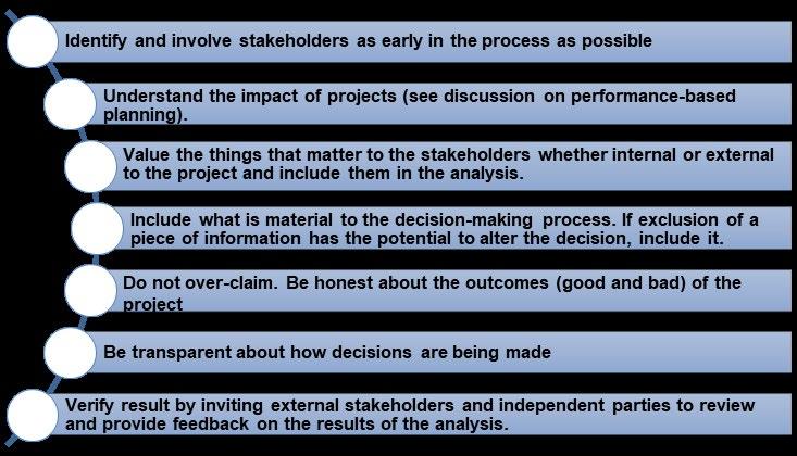
Figure 11.4: Social Return on Investment Principles
transparent manner, there is room in the process for additional information and adjustment to the methodology.
During MMP development the City worked with the steering committee, City leadership and staff, community stakeholders, and the public to develop performance measures to evaluate whether a plan, program, or project helped achieve the MMP goals. Performance measures addressed transportation criteria such as roadway safety, traffic congestion, and mobility, but also addressed non-transportation criteria such as quality of life, economic vitality, and social equity in the distribution of benefits.
TEMPLE MOBILITY MASTER PLAN 211
11.3.2 USE MMP TOOLBOX TO SUSTAIN THE PLANNING PROCESS
The MMP GIS data layers and the analytical planning tools used in the comprehensive systems analysis and scenario-based planning analysis provide a resource toolbox to sustain continuation of the planning process and implementation of the MMP. Use of these resources will allow the City to continue the MMP performancebased planning into the project delivery process to support implementation.
For example, as growth and development patterns evolve over time, the City can use the KTMPO travel demand model to evaluate the transportation demand stimulated by new growth or revised development patterns in response to changes in the transportation system. The TransModeler operational analysis model provides a tool for analyzing level-of-service outcomes of these development pattern changes.
In fact, because the TransModeler based MMP operational model covers the entire City thoroughfare system, it provides an opportunity to analyze the traffic impacts of proposed developments, not one site at a time, but rather as a part of the overall growth patterns and development expected to occur across the entire cityscape. The City can then evaluate not just the isolated impacts of one development, but also the cumulative impact of all current and proposed development.
11.3.3 APPLY SOCIAL RETURN ON INVESTMENT PRINCIPLES
The MMP was community directed and used feedback from substantial and effective stakeholder outreach and public participation to consider how the multimodal transportation system affects the various aspects of the community’s stated plans and aspirations across the whole spectrum of community goals. This approach is commonly referred to as measuring a policy, program, or project’s Social Return on Investment.
Continuing the social return on investment concepts used in the development of the MMP helps to resolve conflicts during
implementation by fully communicating the outcomes (good and bad) of proposed projects in a transparent process. The seven SROI principles to incorporate into the implementation process are shown in Figure 11.4 Social Return On Investment Principles.
11.3.4 COMMUNICATE – COORDINATE –COLLABORATE
To incorporate the performance-based planning and SROI concepts into the implementation process the City should maintain both and inward facing and outward facing education and coordination process. The inward facing process should be directed toward City department leadership and staff to ensure everyone is aware of how the MMP is integrated with other City processes and each department’s role in achieving MMP goals and objectives.
Orient city staff across all departments and sections that will have a role in the implementation process on the MMP approach, processes, and standards to ensure that City internal stakeholders are all operating from the same set of requirements. Nothing undermines trust faster than when a developer or property owner makes a diligent, good faith effort to identify and comply with requirements, criteria, and standards only to be denied approval because another department than the one they initially dealt with is applying different rules, standards, and criteria. One upcoming opportunity to foster this coordination is the scheduled update to the Unified Development Code.
Code Revisions to Incorporate MMP Cross-Section and Design Standards.
During the City’s upcoming UDC update, engage Planning, Public Works and any other departments that are a part of the MMP implementation process in the update of subdivision regulations, site development requirements, roadway design standards, and any other transportation related components of the UDC to ensure that all departments understand the MMP recommended thoroughfare alignments, cross-section components, and design standards, and have adopted them into their departmental
TEMPLE MOBILITY MASTER PLAN 212
review processes. The UDC revision process and adoption of new standards does not have to rigidly incorporate the MMP recommended standards. The UDC process should be used as an opportunity for continuous improvement. If concerns or conflicts in standards arise, they should be discussed, resolved based on all information available about the objectives of each departments position. The MMP is a conceptual document, and its criteria and standards can be adjusted to meet the realities of competing demands.
However, the maintenance of transparency and consistency then requires that any adjustments to the MMP standards made during the UDC process must be incorporated into an amendment to the MMP. As a companion to UDC update, the City should update its detailed engineering diagrams and guidance documents to incorporate and provided additional detail for the final design criteria and standards.
Workflow Collaboration
As part of the internal coordination process, the City should develop a program for monitoring companion departments maintenance and repair activities such as drainage and pavement preventive maintenance and rehabilitation. This coordination can present opportunities to leverage implementation of improvements and enhancements such as sidewalk amenities or bicycle facility striping as part of the planned project.
The consistent processes and messaging developed during this inward facing communication, coordination, and collaboration with internal stakeholders within City department leadership and staff provides the foundation for an inclusive and transparent outward facing education and communication process which begins with potential planning partnerships.
11.3.5 STRATEGIC REGIONAL AND COMMUNITY PARTNERSHIPS
As the first step in the MMP external communication process, the City should present the MMP to its regional and community partners. The City should encourage these partner organizations
to introduce the MMP to their constituents and encourage them to consider the MMP policies, recommendations, and standards when making their own plans and decisions.
To take advantage of the various funding mechanisms and financial strategies described in this implementation plan, it is also important for the City to maintain its current strategic partnerships and create new strategic partnerships to address new modes and innovative mobility solutions. Some strategic partners administer parallel planning processes and funding programs that are essential to the City’s efforts to implement the MMP. Other strategic partners operate and maintain aspects of the transportation system in Temple. Strategic partners also work with and interact with Temple stakeholders and are parties to land use and economic decisions that may affect the implementation of the MMP.
KTMPO / TxDOT and Other Regional Planning Partners
As the regional planning entity for the Killeen-Temple Urbanized Area, KTMPO is responsible for distributing federal and state transportation funds through the development of a Metropolitan Transportation Plan (MTP) and a Transportation Improvement Program (TIP). Federal regulations require the MTP and TIP to be fiscally constrained, showing that funding is or will likely be secured for the included program of projects over the plan horizon. Through its regional plans, KTMPO prioritizes and funds a program of multimodal transportation projects. KTMPO consults and coordinates with TxDOT on programming many of the federal and state program categories, but KTMPO has primary responsibility for allocating and programming several of the funding categories discussed in the previous section, including the Surface Transportation Block Grant Program (TxDOT UTP Category 2 and 4).
The City should continue its leadership role within KTMPO to help shape decision making and to ensure that the MMP project delivery process remains consistent with KTMPO project selection and prioritization processes.
TEMPLE MOBILITY MASTER PLAN 213

TEMPLE MOBILITY MASTER PLAN 214
Figure 11.5: MMP Scenario 2 / Bellaire NPD Project at Shell and Young
Texas Department of Transportation
TxDOT not only administers and programs all the state and federal transportation implementation funds in cooperation with KTMPO, TxDOT owns, operates, and maintains many of the roadways within the City of Temple. Full implementation of the MMP requires that the recommendations be applied to projects on TxDOT roadways as well as on City owned streets. The City should work closely with TxDOT to ensure that the MMP principles are fully understood and collaborate with TxDOT to fully apply MMP concepts where possible.
Intermodal Transportation Operators
The Draughon-Miller Central Texas Regional Airport and area railroads such as the Burlington Northern and Santa Fe Railroad and the Temple & Central Texas Railroad, own and operate large scale transportation infrastructure that interacts with the Temple mobility network. They also operate large scale intermodal activity centers that generate traffic on the mobility network. The City should collaborate and coordinate with these intermodal transportation providers to integrate their infrastructure and transportation activities into the MMP vision.
Hill Country Transit District
Hill Country Transit District operates the regional transit system providing both rural transportation and fixed-route service (the HOP) within the Killeen-Temple Urbanized Area. The Transit Vision Plan recommended continued strategic planning regarding the HOP. To implement this recommendation the City should begin the next phase of strategic planning by discussing the Transit Vision Plan with HCTD and collaborate on identifying benefits and costs, potential governance structures, operating model, and other topics, including the role HCTD might play in implementing the Transit Vision Plan.
Neighborhood Planning Districts
The Neighborhood Planning Districts have a key role in city planning efforts. Many of the MMP project recommendations were made based on input from the respective neighborhood plans.
The City should present the MMP with emphasis on the NPD role in the MMP process, particularly regarding concept development such as the planning and design of MMP neighborhood active transportation connection corridors.
Independent School Districts
The school districts in the area design and build school facilities that act as major traffic generators. They also construct on-site and site adjacent transportation facilities to serve their school communities. The City should present the MMP to the ISDs to introduce elements of the MMP, particularly the Safe Routes to Schools aspects of the plan. The ISDs should be introduced to the role they can play in making the MMP a success and communicating the MMP active transportation vision to their school communities.
Reinvestment Zone No. 1
Reinvestment Zone No. 1 is a City construct and therefore should be included in the inner facing communication and coordination process. But the Reinvestment Zone Board, Project Committee and RZ Managers, work with developers on site development and recommend projects for implementation. The City should introduce the Reinvestment Zone leadership to the MMP and encourage them to further communicate the concepts and principles as they interact with developers, businesses, and the community to ensure that the activities that the Reinvestment Board oversees are consistent with MMP goals and objectives.
Temple Economic Development Corporation (TEDC)
TEDC works with property owners and developers on site identification, site development, and other activities that provide an opportunity to communicate MMP standards and principles. The City should work with TEDC to encourage site developers to include MMP supportive elements into their site plans and facility designs.
TEMPLE MOBILITY MASTER PLAN 215
Business Organizations and Business Owners
Business Organizations such as the Chamber of Commerce and the Temple Area Business Association can be instrumental in the successful implementation of the MMP. The City should introduce these organizations to the MMP with particular emphasis on the economic vitality goals and objectives of the plan.
Business owners are also site owners who can help with the issue of how to make that last vital connection between the public active transportation network and their front door. This last connection is typically on private property and the site owner’s willingness to design their site to integrate their facility with the active transportation network is a valuable component of implementing the MMP mobility network.
11.3.6 PUBLIC PRIVATE PARTNERSHIP
As discussed previously in Section 11.2.4.6 under Funding and Financial Strategies, the City may work with the private sector to share costs of transportation investments. Transportation improvements not only benefit the residents and businesses of the City in the form of improved mobility and safety, but they also have the potential to bring direct benefits to landowners, area developers, and other organizations. Public-private partnerships (PPP) are a fiscally responsible way to conserve public resources by working with third party groups to fund all or a portion of transportation improvements in proportion to the benefits each party is anticipated to receive. Working with cost sharing partners eases the financial burden on the City and maximizes benefits to the public.
Developer Built Streets and Roadways
A common example of this type of public-private collaboration is a thoroughfare planning agreement between a landowner or private land developer and the City. Under such an agreement, the developer may donate ROW, as well as design and build a street or road that provides access to or travel through a specific development. In this situation, the developer typically pays the entire cost of the road, but if the facility provides mobility beyond
the direct needs of the development, the City may participate in cost sharing to fund additional design elements that primarily support broader mobility needs. Once completed, the developer eventually dedicates the roadway to the municipality as a public convenience. When the City accepts dedication, it becomes responsible for maintaining the facility. In this way the costs are shared as the developer bears the initial one-time construction costs, and the City bears the continuing maintenance and upkeep responsibilities over time. Similar dedications can be used to preserve ROW for future project development.
In this type of PPP, the City of Temple UDC provisions, such as the subdivision regulations, design guidelines and standards, and the typical cross-section design guidelines in the MMP serve as a starting point for establishing minimum requirements for privately funded roadway construction. It is important that the developer and the City understand and agree on design standards and cross-sections associated with the transportation facility in question.
New Mobility and Smart Cities Vendors
As new technologies emerge, it is impossible for a city or agency to keep apprised of each as they emerge and more so keep track of what is potentially useful for their locale. Frequently these involve a public/private partnership that offsets some or all the project costs through private investment.
Because new mobility and innovative technology vendors are businesses operating for profit, they can be expected to carry out some phases of project delivery at their own expense. Cities across the US have adopted policies for accepting unsolicited proposals which help them to have a policy to follow if or when a new technology vendor or project opportunity arises. If the City wants to be more targeted about their request, they can also request proposals for new technologies without necessarily having a budget for implementation. They can request that the proposer also submit a plan for financing the project or infrastructure.
TEMPLE MOBILITY MASTER PLAN 216
11.3.7 PUBLIC PARTICIPATION AND STAKEHOLDER ENGAGEMENT
The City approached the MMP with the desire that it be a community directed plan and for the most part succeeded in that goal. Stakeholder engagement was effective and productive, and stakeholders provided substantial input to help shape the plan. In keeping with the social return on investment principles of the implementation plan, the City should continue its robust public outreach and stakeholder engagement during the implementation process.
The City should collaborate with community partners to communicate the MMP goals and objectives, how recommendations were developed, and how decisions were made. As the MMP moves into the implementation phase, explain how each project fits into the bigger picture of overall City mobility. Going through this exercise, will not only produce more support for projects, but may also help to select and design better projects that coordinate with other initiatives, which will ultimately improve the mobility of the entire system.
11.4 MMP IMPLEMENTATION PLAN AND THE MOBILITY CIP
The Implementation Plan outlined in this chapter provides a description of the project delivery process, funding mechanisms, strategic partnerships to foster project delivery, action items to accomplish sustainable project delivery, and guidance on conflict resolution and decision making leading to sustainable implementation of the MMP recommended projects. The MMP initiates one of these steps in the project delivery process through the selection of candidate projects and development of project priorities. The project selection process used the MMP goals, objectives, and the reported Comprehensive System Assessment performance measures to develop a prioritized Program of Projects for inclusion in the City of Temple Mobility Capital Improvement Program.
Chapter 12 Capital Improvement Plan describes the development of this Program of Projects, provides a narrative overview of the priority projects, and presents the Capital Improvement Plan containing the priority projects with program level opinions of probable cost and a preliminary timeline of program expenditures.
TEMPLE MOBILITY MASTER PLAN 217
Goals and Objectives
Figure 11.6: MMP Goals and Objectives
Safety First
+ Vision Zero - Achieve zero fatalities by 2050
+ Achieve an overall reduction in traffic fatalities of 30% by 2030.
+ Achieve an overall reduction in serious injuries of 30% by 2030.
+ Reduce crash rate on public roads to 100 crashes per 100M VMT.
+ Reduce bike-ped fatal and serious injury crash rate to 0% per 100M VMT by 2030.
Choices
+ Provide new mobility options to broaden the choice set for all travelers.
+ Reduce SOV by 20 %.
+ Increase bike/ped facility usage by 50%.
+ Increase transit ridership to pre-COVID levels, once benchmark is reached, continue to increase by 5% annually.
+ Provide mobility improvements so drivers/ travelers can select their destination based on the quality of the destinations, not quality of their trip.
+ Evaluate emerging technologies on a biannual (every two years) basis to consider modifications to the planning and design process to incorporate new modes, technology and best practice.
Connections
+ Number of mode choices within 1/2 mile of residence or place of employment
+ Reduction in walk distance to transit stops.
+ Reduction in the number of gaps in the sidewalk / bike system.
+ Sidewalk / bike facility miles.
+ Improve terminal time at destination through improved parking and access management strategies.
Prosperity
+ Opportunity/Equity* -improve low income and minority transit access by 50%.
+ Social Vulnerability Index - Combined housing and transportation costs reduced by 25%.
+ Reported improvement in on-time / justin-time delivery.
+ As value increases, work with members of community and outreach organization to manage and mitigate impacts
*Equitable as it pertains to all personsa best equal distribution, location, and impact of improvements
Fund and Implement
+ Provide a project selection and prioritization process that increases City competitiveness across all modes in planning partner (regional and state) infrastructure funding programs.
+ Develop and fund program to regularly monitor and address roadway condition to support ‘state of good repair’ objectives (Objective 1 under Maintain and Sustain).
+ Increase level of dedicated funding for transportation by 25%.
+ Provide data and planning resources to improve the city’s capability to capture available grant funding
+ Provide development plans that support strategic initiatives that improve funding for transit and active transportation
+ Strategically match allocated maintenance budget to annualized state of good repair targets under the Maintain and Sustain goals and objectives.
+ Strengthen public/private partnership funding opportunities to ensure infrastructure investment sufficient to support growth and new development.
Community Driven
+ Number of contacts through the stakeholder engagement and public meeting process.
+ Number of groups addressed through speaking engagements requested / carried out.
+ Demonstrate to the public how their input was used in the MMP decision making process.
+ Empower champions for the MMP to support strategic initiatives and action steps that lead to implementation.
Mobility
+ Reduce congestion related delay by 50%
+ Transportation Systems Management and Operations (TSMO) improvements/ efficiencies to improve major corridor level of service (LOS) by 50%
+ Improve average intersection level of service by 75%
+ Minimum intersection level of service at C.
+ Improve transit out of vehicle travel time by 50%
+ Improve transit in vehicle travel time by 25%
+ Reliable primary system with an 10 minute planning index and <1.0 reliability index.
+ Freight reliability to promote dependable commerce/just in time delivery/mobile warehousing, with a 1.0 Truck Travel Time Reliability.
Maintain and Sustain
+ State of good repair - 90% of roadways in state of good repair (at or above PCI of 80).
+ 75% of bridges in good condition.
+ 0% bridges in poor condition.
+ Resiliency - Evaluate design standards to extend design life by meeting demand load and weather related stress events.
+ Redundancy - provide available alternate routes in case of major crashes or impediments.
Quality of Place
+ Context sensitive system that promotes neighborhood integrity and property values.
+ Context sensitive system that protects cultural resources and historical sites.
+ Protects the natural environment (air quality; water quality; wetlands and flood plain).
+ Design elements and functionality that promote a sense of community and provide amenities such as shelters, trees, and/or shading.
TEMPLE MOBILITY MASTER PLAN 218
templetx.gov/mobility
This page intentionally left blank
TEMPLE MOBILITY MASTER PLAN 219
CHAPTER 12
MOBILITY CAPITAL IMPROVEMENT PLAN

12. MOBILITY CAPITAL IMPROVEMENT PLAN
12.1 INTRODUCTION
To kickstart the MMP Implementation Plan, the MMP presented a program of candidate projects that the City should consider for funding and implementation through the project delivery process. The MMP prioritized projects based on their relevance to achieving MMP goals and objectives using the performance measures defined in the Comprehensive System Assessment. The project prioritization process selected projects from the program of projects for inclusion in the Mobility Capital Improvement Program based on each project’s priority and readiness for implementation.
12.2 MOBILITY CAPITAL IMPROVEMENT PROGRAM
The City of Temple Capital Improvement Plan is a community planning and fiscal management tool used to coordinate the location, timing, and financing of capital improvements over a multi-year period. The City of Temple Capital Improvement Program focuses on large-scale, non-routine capital expenditures, generally exceeding $100,000, that would otherwise cause a significant impact on the operating budget. The Mobility Capital Improvement Program is a component of the overall Temple CIP.
The Mobility Capital Improvement Program (MCIP) provides recommendations for mobility related capital infrastructure investments, maintenance, and repair drawn from the MMP to support the City’s mobility vision, goals, and objectives. It also includes preconstruction expenditures to support project delivery such as feasibility studies, preliminary engineering, and design work.
12.2.1 PROJECT SELECTION
As part of the implementation plan development process, the MMP used the recommendations made in Chapter 10 to define a program of candidate projects that will improve the mobility network. Project identification started early in the MMP process based on input from the public, the steering committee, and other community stakeholders regarding unmet transportation needs, network gaps, connectivity issues, and locations experiencing safety or congestion issues.
The project identification process integrates information from other planning efforts, both completed and ongoing. Recommendations and priority projects were sourced from the Comprehensive Plan, Thoroughfare Plan, Neighborhood Planning Districts, and the Parks and Trails Master Plan, and other documents.
The project identification effort continued during the technical analysis phase of MMP development. The Comprehensive System Assessment helped to quantify and evaluate the issues identified by the public and previous plans and identified additional problem locations by reporting and quantifying future anticipated safety issues or level of service deficiencies. The system assessment also identified multimodal mobility challenges, access issues, and network gaps that the City should address to optimize the mobility system.
The Scenario Analysis provided recommended solutions to the mobility challenges identified through these various sources in the form of program, policy, and individual project recommendations that form the basis of the MMP program of projects. The next step in the process was to prioritize the candidate projects based on each projects ability to address the MMP goals and objectives based on the performance measures defined in the systems assessment and scenario analysis.
TEMPLE MOBILITY MASTER PLAN 221
The MCIP helps the City's Planning, Public Works, and Finance departments coordinate the City's strategic planning, financial capacity, and physical development of mobility infrastructure.
12.2.2 PROJECT PRIORITIZATION PROCESS
The MMP prioritization process used performance measures identified in the CSA and scenario-based planning analysis to develop the prioritized program of projects. The process scored intersection improvements and roadway capacity projects using crash rates for fatal and severe injury crashes, AM and PM peak levels of service, connectivity, and linkage to other projects, plans and programs.
The prioritization process scored active transportation and complete-streets projects using pedestrian and bicycle crash rates, level of demand, level of traffic stress scores, proximity to schools, network connectivity to existing active transportation infrastructure and activity centers, and linkage to other plans and programs.
The prioritization process also included work sessions with the City project team to score projects based on their impact on overall mobility, economic vitality, quality of place, and social

equity based on reported findings of the previous analysis and input from community stakeholders, the public, and other parallel planning processes.
The first step in the prioritization process was to review the projects selected for inclusion in the MMP program of projects and rank each project based on the reported performance measures for that category of project. This stage of the screening process revealed the projects that addressed the most severe deficiencies and the projects that addressed deficiencies across multiple performance categories.
The process also reviewed whether the projects intersected or interacted in a way that warranted combining certain projects. For example, combining a recommend intersection project with a roadway project on the corridor containing the intersection, or combining sidewalk or bicycle improvements with a proposed roadway project to create a complete-streets concept for the corridor.


TEMPLE MOBILITY MASTER PLAN 222
Figure 12.1: Types of Projects
Intersection Improvement Projects
Complete Streets Projects
Roadway and Corridor Projects
Operations & Maintenance Projects
Active Transportation Projects
Safety Projects
Figure 12.2: Project Selection and Prioritization Process
• Connectivity and Reliability
Stakeholder Input
• Economic Vitality
• Social Equity
Comprehensive Systems Analysis
• Congestion
• Safety
• Reliability
Scenario Analysis
• Level of Stress
• Multimodal Connectivity
Project Selection
• System Performance
• Project Work Sessions
• Readiness for Implementation
Prioritized Program of Projects
TEMPLE MOBILITY MASTER PLAN 223
Following this first-round of project scoring, the prioritization process moved to a series of work sessions, from late May through mid-June, with the City project team and available subject matter experts to review projects based on the more qualitative performance measures. In addition to reported system performance, the discussion included each project’s impacts on the City’s economic vitality, quality of life and quality of place including how neighborhood residents and businesses perceived the project. The work sessions also included a discussion of the project’s current state of readiness within the project delivery process, particularly if there was the potential for external grant funding.
The prioritization process also included a work session with the City Council on February 2, 2022, in which the council members reviewed the prioritized program of projects and provided observations on potential gaps or omissions based on the input from community residents or parallel planning processes. The prioritization process concluded with the development of the MCIP priority projects.
12.2.3 PROJECT READINESS FOR IMPLEMENTATION
Priority projects must go through an additional step before they appear in the MCIP. The MCIP is a relatively short-term strategic planning document covering about seven years. The current MCIP covers the fiscal years 2022 through 2028. Securing the funds to implement a project, particularly a large-scale project, may take several years. Often pre-implementation activities are necessary to provide sufficient project detail to estimate costs. City staff must responsibly and intelligently program projects in order to minimize frustration created by unmet needs. Programming a project in the MCIP that is not far enough along in the project delivery pipeline for implementation is inefficient and detrimental to the overall MMP vision. A project programmed prematurely may , tie up available resources, while other projects that could have made a positive impact if implemented, instead remain unfunded and incomplete.
If project implementation cannot proceed within the seven-year window provided by the MCIP, then preconstruction activity such as preliminary engineering or environmental assessment may be the only element in the MCIP. In the case of large projects funded through external programs, even the preconstruction activity may not be feasible within the MCIP window. Under these circumstances, some high priority projects may not appear in the MCIP, while less important projects that are fully ready for implementation may be programmed for funding while work is done to bring the higher priority projects into readiness for implementation and secure funding. The following sections describe the MCIP projects, funding levels, funding sources, and likely project timing.
12.3 MOBILITY CAPITAL IMPROVEMENT PROGRAM PROJECT NARRATIVE
The MCIP contains projects from various mobility categories including roadway capacity and connectivity projects, intersection improvements, operations and maintenance projects, multimodal mobility/active transportation projects, and projects derived from parallel planning efforts.
12.3.1 CAPACITY AND CONNECTIVITY PROJECTS
Phases III & IV of the Kegley Roadway improvements. This project will extend from the end of Phase II to the intersection of Charter Oak Drive. Improvements include expanded pavement sections with a continuous left turn lane, pedestrian facilities, drainage conveyance, utilities, and an elevated bridge structure over Pepper Creek. Improvements will take this rural road and turn it into a minor arterial providing an alternate route for traffic from IH-35 to the west side of town.
Line 1 - Kegley Roadway Improvements, Phase III & IV at $9,750,000
The North 42nd Street reconstruction project. This project consists of roadway improvements to North 42nd Street from Lavendusky Drive to Hillcrest Road and Loop 363. Improvements
TEMPLE MOBILITY MASTER PLAN 224
include an expanded pavement section with continuous left-turn lane, pedestrian facilities, drainage conveyance, and water utilities. The project is in the plan in response to both citizen requests for street improvements and planned development activity in the area. Design began in FY 2021.
Line 2 – 42nd Street Reconstruction at $4,950,000
Hartrick Bluff Road. The reconstruction of Hartrick Bluff Road from FM 93 to Waters Dairy Road was funded in FY 2021. Those improvements will take this rural road and turn it into a collector providing service to residential subdivisions along this corridor. With that project underway, and to better serve new development in recently annexed areas south of FM 93, staff is recommending 30% design of the next phase of Hartrick Bluff. This design will provide an evaluation of needed ROW and assess the impact of possible construction should the need for road improvements continue to accelerate in this area.
Line 3 – Hartrick Bluff Road (South of FM 93) at $600,000
Midway Drive. This roadway is a four-lane wide collector running from IH-35 to Hickory Drive and carries approximately 8,400 vehicles per day. It serves as a significant east-west connector and has received several overlays over time. However, maintaining a smooth road surface in this area continues to be a challenge due to difficult soil conditions. Reconstruction of the road will require additional excavation and select fill to reduce the potential vertical rise of the roadway and extend the life of the road surface. Staff is recommending 30% design begin in FY 2023 order to better evaluate rights-of-way and opinions of probable cost.
Line 4 – Midway Drive (IH-35 to Hickory Road) at $1,125,000
Designation of I-14. The TxDOT projected designation of Loop 363/SH 36 as I-14 may require City of Temple participation. City staff estimated that participation consists of one percent of the project cost. The one percent estimate is based on ten percent of right of way acquisition and utility relocation costs. Ongoing coordination with TxDOT will clarify Temple’s financial participation and incorporate feedback received during the MMP process.
The Outer Loop. The loop will ultimately create a new major arterial loop around Temple, connecting regional employment centers to neighborhoods and interstate commerce. This loop strategically combines several existing roadways and thoroughfares, including Moores Mill Road, Old Howard Road, Hilliard Road, Research Parkway, and Old Waco Road. Several segments in west Temple have already been completed. Outer Loop North Phases I-III stretch from IH-35 to Airport Road and will provide direct connectivity along the new thoroughfare between freight companies and IH-35. From Outer Loop North, drivers benefit from a short trip to the Draughon-Miller Airport and direct connectivity to the proposed 750-lot Westfield mixed-use development and the recently completed 300+ acre Crossroads Athletic Park The nearest section of IH-35 carries 78,656 vehicle per day, and 15,020 vehicles travel daily on northwest Loop 363. Allowing the traffic to disperse onto the Outer Loop will significantly reduce congestion. Outer Loop West, Phase I (OL-W1) was submitted for funding through the Killeen-Temple Metropolitan Planning Organization (KTMPO) Call for Projects in 2018 and was awarded $8,300,000 in funding. With the City funding its grant match for construction in FY 2021, this section is scheduled for completion in FY 2023. Outer Loop West, Phase II (OL-W2) was approved for funding though the KTMPO Metropolitan Transportation Plan (MTP). An Environmental Assessment of the corridor is currently underway.
12.3.2 MMP INTEGRATION WITH OTHER PLANNING EFFORTS
Neighborhood Planning Districts
The City of Temple is dedicated to fostering cohesive, distinct, vibrant, safe, and attractive neighborhoods, where citizens take pride in where they live and are engaged with their community. The Love Where You Live Program identifies eighteen Neighborhood Planning Districts (NPD) that form the core of the community. Each district plan has a similar planning process that is intended to complement the City’s Comprehensive Plan with a more focused effort at the neighborhood level. These plans look at the existing conditions and engage residents to derive genuine information and direction from each NPD. While using
TEMPLE MOBILITY MASTER PLAN 225
Line 5 – Designation of I-14, City Participation at $1,500,000
Line 6 - Outer Loop West, Phase II at $12,900,000
the best practices for planning, the results of each plan define specific recommendations that are unique to each planning area. The MMP project prioritization process included future mobility projects identified through the NPD planning effort into the project prioritization process and incorporated high scoring NPD projects into the MCIP.
Avenue D Connections and Alley. This project consists of roadway and pedestrian improvements for Avenue D from 14th Street to 18th Street, construction of a new roadway from Avenue D to Avenue E, alley improvements between Avenue C and Avenue D from 14th Street to 18th Street, and alley improvements between Avenue D and Avenue E from the new roadway adjacent to Jeff Hamilton Park to 18th Street within the Ferguson Park Neighborhood Planning District. The proposed project will include reconstruction of a two-lane roadway with curb and gutter, sidewalks along both sides of the street, landscaping, irrigation, lighting, alley driveway access, and sidewalks leading to the front doors of the residences. Currently, Avenue D is a narrow roadway with no pedestrian improvements. Relocating the driveways to the rear of the properties to be accessed from the alleys will provide a safe connective pedestrian corridor for the neighborhood residents. The addition of lighting will increase the overall safety for pedestrians and motorists and the landscaping will significantly improve the overall aesthetics of this roadway corridor.
Line 7 - Ave D Connections and Alley at $2,400,000
1st Street Sidewalks. This project consists of pedestrian improvements along 1st Street from Zenith Avenue to Shell Road within the Bellaire Neighborhood Planning District. The proposed project will include 5-foot sidewalks along both sides of 1st Street, lighting, street trees, landscaping, and bicycle lane markings. 1st Street has a special designation as both a neighborhood collector and a bicycle route. The addition of street markings and signage will help to improve vehicle awareness of the bicyclist’s presence. This project will maintain the existing right-of-way to preserve landscape areas, street trees, and the overall pedestrian environment.
Line 8 - 1st Street Sidewalk, Zenith to Shell at $1,400,000
Henderson Parkway. This project consists of improvements to Henderson Parkway and Knob Creek Trail. The project consists of a new parkway and shared use path extending from Henderson Street to Avenue N within the Crestview Neighborhood Planning District. The proposed project will include two twelve-foot travel lanes, on-street parking, a sidewalk on the east side of the roadway and a 12-foot trail with lighting, signage, trash cans, and benches on the west side. This trail will enhance the overall quality of life for the Crestview Neighborhood residents by providing recreational opportunities and safe connectivity both within the neighborhood and to adjacent neighborhoods (including the 14th St. Trail in the Ferguson Park Neighborhood Planning District, while the parkway provides an alternative route to access the BNSF crossing at 24th Street.
Line 9 - Knob Creek Trail and Henderson Parkway $9,285,000
3rd Street Sidewalks. This project consists of pedestrian improvements along 3rd Street from the Cultural Activities Center to Downtown Temple within the Bellaire, Historic, and Central Neighborhood Planning Districts. The proposed project will include the construction of new sidewalks and repairs to existing ones along 3rd Street to beautify a primary corridor leading into Downtown Temple. Physical improvements, such as ADA ramps and sidewalks, will directly contribute to a higher quality of life by enabling active transportation modes such as walking and cycling.
Line 10 - 3rd Street Sidewalks, Convention Center to Downtown at $2,700,000
TEMPLE MOBILITY MASTER PLAN 226
The Rail Line Linear Trail. This project consists of pedestrian improvements alongside the BNSF railway from Optimist Park to French Avenue within the Historic Neighborhood Planning District with a future expansion that will extend the trail to connect to downtown at Santa Fe Plaza. The proposed project includes construction of a 10-foot concrete trail, signage, and fencing between the railway and the trail. Working with the railroad company to develop a greenspace buffer, a trail along the railway in the Historic Neighborhood Planning District will create a safe and functional recreational area that provides pedestrian connectivity from the existing park to key destinations within Temple.
Line 11 - Rail Line Linear Trail at $7,700,000
14th Street. This project consists of pedestrian improvements along 14th Street from Adams Avenue to Avenue H within the Ferguson Park Neighborhood Planning District. The proposed project will include the construction of a 12-foot trail, split rail fence, landscaping, and pedestrian lighting. There are currently no pedestrian improvements along this major corridor making it unsafe for pedestrians who utilize this roadway to reach key destinations. This trail will enhance the overall quality of life for the Ferguson Park Neighborhood residents by providing recreational opportunities and safe connectivity both within the neighborhood and to adjacent neighborhoods.
Line 12 - 14th Street Trail from Central Ave to Ave H at $5,200,000.
Parks - Sidewalks and Trail Connections
The Georgetown Railroad Trail Phase I. This multiphase project creates a ten-foot (10’) wide, 4-mile long shared-use path along the right-of-way of the former railroad. This rails-to-trails project ranks as a Priority Trail in the City of Temple Trails Master Plan for its potential to connect key destinations and neighboring communities. The design will include safety lighting and signage at all street crossings to minimize risk to pedestrians and cyclists and encourage use by students. The trail will be easily accessible to residents living in Stonegate, Echo Village, Wyndham Hill, Sarah’s Glenn, Alta Vista, Deerfield, Bentwood, and Legacy Ranch.
The trail will connect Raye Allen Elementary School, South Temple Community Park, and ultimately reach the historic MK&T bridge over the Leon River. Phase I of the project starts near Raye Allen Elementary School 0.04 miles east of S. 5th St. and extends to S. 31st St (FM 1741). It is in the KTMPO TIP (KTMPO ID T40-13a) using a combination of funding sources, including Surface Transportation Program Funds (Category 7) and the Transportation Alternatives Program (Category 9), and Non-Traditional Funding (Category 3).
Line 14 – Georgetown Railroad Trail Phase I at $1,300,000
Georgetown Railroad Trail Phase II. This phase of the trail project extends from S. 31st St. (FM 1741) to the MKT Bridge over the Leon River. It includes the renovation of the Historic MKT Truss Bridge, constructed in 1882.
Line 15 - Georgetown Railroad Trail Phase II and MKT Bridge$3,300,000
Pepper Creek Trail. Planning for the future Pepper Creek Trail Extension and FM 2305 Pedestrian Bridge rehabilitation began in FY 2021 in preparation for grant consideration. This trail will tie into the existing trail on the north side of the pedestrian bridge, allowing pedestrians to cross under FM 2305 and exit on the south side to a sidewalk connection near Kegley Road. In FY 2022, $650,000 was allocated to design, with an additional $2,700,000 for construction in the funding schedule for FY 2026.
Line 16 – Pepper Creek Trail Extension at $3,350,000
East Temple Sidewalks. Staff has developed a project based on conceptual alignments from the Ferguson Park and Crestview Neighborhood Plans. The proposed improvements will construct a six-foot sidewalk along the east side of S. 14th Street from E. Central Avenue to Henderson Street. The sidewalk will transition to a ten-foot shared-use path starting at Knob Street, generally following the drainage channel, and ending at S. 24th Street. The estimated construction cost for this project is $1M. Grant matching funds are in the MCIP in anticipation of receiving external funding through discretionary funding programs.
Line 17 – East Temple Sidewalks at $200,000
TEMPLE MOBILITY MASTER PLAN 227
East Central Sidewalks. East Central Avenue is a well-traveled thoroughfare connecting IH-35 to downtown with a high school, a grocery store, and several neighborhoods all along the way. The sidewalk contains several gaps that need to be addressed to provide a safe route adjacent to this busy roadway.
Line 18 - East Central Sidewalks at $650,000
12.3.3 OPERATIONS AND MAINTENANCE
Once a project is in place and open to the public, it becomes an asset that requires ongoing attention in terms of operations and maintenance (O&M). The MCIP includes recurring funds to ensure adequate O&M budget to address the expansion and complexity of the multimodal mobility network. Staff should periodically review the operations and maintenance budget and adjust funding levels dedicated to signal operation and maintenance, signage installation and repair, and roadway and sidewalk pavement management.
Traffic Control and Signals
Signal Replacement and Upgrade Program. There are currently three intersections within the City of Temple that meet TXDOT warrant standards for a signal at the intersection: Orion at SH 317, Poison Oak at SH 317, and Hartrick Bluff at FM 93. Road improvements underway in FY 2021 for Hartrick Bluff include the required signal installation along with the road construction. The MCIP funding schedule includes installation of the Orion and Poison Oak signals in FY 2022 with a placeholder for future intersections. The MMP recommended increasing the recurring funding in response to rising costs and to provide financial capacity to address MMP proposed signal studies and corridor improvement studies. Among other locations, the MMP recommends coordination with TxDOT to study and improve the intersections and signals for Airport Road at N. 25th Street and Airport Road at N. 29th Street.
Line
31st Street Signal Design/Optimization Study. To improve traffic capacity and reduce delays along 31st, the MMP recommends a Transportation Systems Management and Operations (TSMO) Optimization Study/Design project from Dodgen Loop/US 190 to W. Adams Avenue. Funds for this corridor optimization study and some limited early-action implementation is included for FY 2023 and FY 2024 at a cost of $1,400,000. The study proposes to include analysis of the intersections at Dodgen Loop/US 190, Avenue R, Avenue H, Avenue M, Avenue D, W Central Ave., and W Adams Ave. in the study.
Line 19A - 31st Street Signal Design/Optimization Study –$1,400,000
Pavement Preservation Program
The 2020 Pavement Management Report (PMR) reported an overall roadway system pavement condition index of seventy-five (75). The 2020 PMR recommended preservation, rehabilitation, or reconstruction of Temple roads, to achieve an overall Pavement Condition Index (PCI) of eighty (80), which represents a five point or seven percent increase in the overall condition of Temple streets and roadways.
Pavement Preservation. The MMP recommends an increase in the programmed funds in the MCIP from $2.5 million per year to $3.25 million per year, subject to operating budget constraints, to ensure that the system achieves the target PCI score, to mitigate the effect of rising costs, and to provide funding for maintaining MMP recommended roadway and sidewalk improvements. The program should also include a periodic update to the 2020 PMR.
Line 20 – Pavement Preservation and Reconstruction at $22,750,000.
12.3.4 COMPLETE STREETS PROGRAM
The MMP describes a vision for a mobility network based upon a set of policies and design standards that provide users of all ages and abilities with transportation infrastructure to move safely and comfortably through the space, regardless of mode. Complete streets principles encourage planners and engineers to consider
TEMPLE MOBILITY MASTER PLAN 228
19 – Signal Replacements, Upgrades, and Additions at $2,050,000
all transportation modes and users of a roadway when designing streets, including bicyclists, transit riders, pedestrians, motorists, youth, elderly, differently-abled, and the able-bodied. The projects in this section strive to achieve that vision.
Martin Luther King Jr. Drive. Complete Streets Improvements to MLK will ensure that users of all ages and abilities can drive, walk, bike, and use transit comfortably on this minor arterial in the Downtown neighborhood. The MMP identified surplus capacity on this section of MLK. The project proposes to use this available capacity to add a ten foot (10’) wide side path to the west side of the roadway, along with intersection enhancements, landscaping, illumination, and ADA compliant ramps and amenities.
Line 21 - MLK Complete Streets Improvements – $8,626,800
Market Loop and Cottonwood Street. Market Loop is one of the main roads through the South 31st Subdistrict of the TMED District, connecting the McLane Children’s Hospital to the Marketplace shopping center and across 31st Street to the Temple Mall. The project sidewalk and safety improvements to Market Loop and Cottonwood St. will create a pedestrian realm, by adding sidewalk, street trees and screening the view of the back of adjacent buildings. Likewise, filling gaps in the sidewalk of Cottonwood Ln. will create a continuous accessible pedestrian way.
Line 22 - Market Loop / Cottonwood Street Sidewalk and Safety Improvements - $1,990,000
S. 25th Street. A Complete Streets upgrade to S. 25th St. from W. Avenue H. to W. Avenue E will improve safety and comfort for people walking, biking, driving, and using transit throughout this corridor. The existing four lane street has relatively low traffic, and the addition of on-street parking, sidewalks, lighting, benches, landscaping, and street trees can calm traffic and improve the pedestrian experience.
Line 23 Complete Streets upgrade of S. 25th from W. H Ave. to W. Ave. in the Midtown NPD - $3,700,000
1st Street Extension. This project will extend 1st St. from its current terminus at US 190 to 5th Street/Waters Dairy Rd. The
arterial roadway will consist of two twelve-foot (12’) travel lanes in each direction, a landscaped median with five-foot (5’) sidewalks on both sides of the roadway.
Line 24 - 1st Street Extension from US 190 to 5th St./Waters Dairy Rd. - $576,400
W. Adams Ave. This corridor is critical for the All Ages and Abilities bicycle improvements because of the corridor’s unique ability to provide east/west access across several significant barriers such as BNSF rail corridor, I-35, and SH 363. The addition of bicycle improvements including striping, signage, and vertical barriers along W. Adams Ave. from Kegley Rd. to 3rd Street will create a dedicated space for bicyclists to travel more comfortably along this key corridor. $614,000 is allocated in FY 2024 for design and a phasing plan.
Line 25 - Bicycle improvements along West Adams Avenue. from Kegley Rd. to 3rd St. - $614,000
Barnhardt Road Improvements. This project will upgrade the existing Barnhardt Rd. from Old 95 to SH 95 from a twenty-foot (20’) wide rural roadway into a complete streets cross section including a median, two twelve-foot (12’) travel lanes, sidewalks, and cross walks. This project is a partnership in collaboration with the Temple Independent School District to improve access to a future school site.
Line 26 - Barnhardt Road from Old 95 to 95 - $6,600,000
12.3.5 SAFETY PROGRAMS AND PROJECTS
As Temple and the surrounding area continue to grow, balancing the enhancement of safety and efficiently maintaining mobility will become more complex. All the priority projects included in the MCIP provide a level of safety benefit. The projects in this section, however, have a primary safety focus to address points of conflict or mitigate the increasingly more complex interactions of different modes of travel.
Safe Routes to Schools Sidewalk Network Program - Promoting walking and biking to school through infrastructure improvements provides a health benefit to the Temple community and promotes
TEMPLE MOBILITY MASTER PLAN 229
active living for the younger generation during their everyday routine. Safe Routes to School (SRTS) promotes safe, convenient, and fun travel options for children and families to bicycle to school and other destinations. The MMP Comprehensive System Assessment reviewed sidewalk density within a ¼ mile walking distance (walkshed) of twenty-two (22) public schools in Temple. The evaluation process prioritized locations with low sidewalk density for future improvements or renovation of existing sidewalks. The Sidewalk Network Program allocates funds for ongoing planning of sidewalk additions and improvements to enhance neighborhood walkability and improve connectivity between neighborhoods and schools. The Sidewalk Network Program promotes project readiness in anticipation of grant applications for SRTS, Transportation Alternatives (TA) or Safe Streets and Roads for All (SS4A) funding.
Line 27 - Safe Routes to Schools Sidewalk Network Program$1,200,000
Safety Realignment and Innovative Intersection Identification. This categorical line item provides planning, design, and implementation funds for use in framing solutions and implementing improvements at locations with network geometry that creates driving challenges or requires vehicle movements that promote turning conflicts. Examples include:
• Locations where roadways intersect at oblique angles diminishing sight lines and making it harder to judge the spacing and speed of crossing traffic.
• Locations where offset intersection approaches require left turns across oncoming traffic.
• Roadways that have unnecessary sharp turns.
• Problem intersections that defy conventional solutions and would benefit from the safety advantages provided by a roundabout or other innovative intersection strategy.
Funds in this line item will help to identify and address these safety issues. Locations identified as having alignment or discontinuity issues during the MMP network field review include Shell at
Young, Hickory at Stratford, and Knob Creek at FM 3117. These locations are a sample of the system, and the City should continue to identify additional locations that exhibit similar alignment discontinuity. The City should also use funds from this line-item help avoid these types of alignment issues in planning and design of future roadways and consider the use of roundabouts and innovative intersection strategies as the City implements the Thoroughfare Plan roadways.
Line 28 - Safety Realignments / Innovative Intersections$2,000,000
Right of Way (ROW) Preservation / Acquisition – This contingency line item provides funds for the City to address shortfalls in ROW acquisition for programmed projects in the light of rapidly increasing real estate costs. This approach helps the City to avoid project delays and disruptive impacts on the operating budget due to unanticipated additional costs. Once prices stabilize and more accurate project ROW cost estimates can be prepared, the City can use these funds to preserve ROW for future planned thoroughfare corridors.
Line 29 - ROW Acquisition / Preservation - $3,600,000
12.4 MOBILITY CAPITAL IMPROVEMENT FUNDING SCHEDULE
The MCIP funding schedule provides a list of the MCIP priority projects programmed for some or all the steps in the project delivery process, with an estimated cost, and an anticipated year of expenditure. The expenditure schedule is an MMP recommended program for the MCIP. When approved, the actual City fiscal document may be quite different based on fiscal constraints and available budget.
12.4.1 FUNDING AND REVENUE SOURCES
Mobility funding comes from a variety of sources. Typical sources of funding include local, state, and federal funding programs as well as private sector/non-governmental sources. When funding for a project is from non-local sources, the amounts shown in
TEMPLE MOBILITY MASTER PLAN 230
the funding schedule generally represent the required local matching share to secure the grant program funding. The MMP Implementation Plan (Chapter 11) provides additional detail about specific sponsored funding programs and discretionary grants available to the City for mobility improvements.
12.4.2 CONCEPTUAL PROJECT COST ESTIMATES
The MCIP project costs are program level costs based on professional ‘opinions of probable cost’ (OPCs) developed by local engineers familiar with the Temple area and past and current trends in unit costs for the various components of project delivery. The engineers performing the work used available information resources such as datasets on average low bid unit prices for the area, recent bids and bid trends for Temple area projects, and informed professional judgment.
The OPCs also take into consideration the scope and scale of the project and the components of the project such as roadway or sidewalk cross-section and the incorporation of bridges or other elevated structures.
The OPC provides a projected program level cost for preconstruction and construction stages of intersection, roadway, and active transportation infrastructure projects shown in the MCIP. The City may need to revise costs as the project progresses through the project delivery process and the City gains additional understanding of project complexity, challenges, and constraints during preconstruction planning and engineering activities. Table 12.1 presents the MMP recommended MCIP Funding Schedule.
TEMPLE MOBILITY MASTER PLAN 231
Figure 12.3: MCIP Potential Revenue Sources
Local General Funds & Certificates of Obligation
Federal Discretionary Grants
Public Private Partnership
State & Regional Funding Programs Private Foundation Grants
TABLE 12.1: MOBILITY CAPITAL IMPROVEMENT FUNDING SCHEDULE
TEMPLE MOBILITY MASTER PLAN 232 MOBILITY PROJECTS FY 2022 FY 2023 FY 2024 FY 2025 FY 2026 FY 2027 FY 2028 FY 2029 TOTAL Capacity & Connectivity Symbol Key: Design Right of Way Construction 1. Kegley Roadway Improvements, Phase 3 & 4 $9,750,000 $9,750,000 2. 42nd Street Reconstruction $4,950,000 $4,950,000 3. Hartrick Bluff (South of FM 93) (30% Design) $600,000 $600,000 4. Midway Drive (IH-35 to Hickory Road) (30% Design) $1,125,000 $1,125,000 5. Designation of I-14, City Participation ^ $1,500,000 $1,500,000 6. Outer Loop West, Phase II ^ $12,900,000 $12,900,000 Neighborhood Planning Districts 7. Avenue D Connections and Alley (Ferguson Park District) $2,400,000 $2,400,000 8. 1st Street Sidewalk, Zenith to Shell (Bellaire District) $1,400,000 $1,400,000 9. Henderson Parkway Improvements $9,285,000 $9,285,000 10. 3rd Street Sidewalks; CAC Downtown (Belair/Historic/Central) $2,700,000 $2,700,000 11. Rail Line Linear Trail (Central and Historic District) $7,700,000 $7,700,000 12. 14th Street Trail - from Adams Ave. to Avenue H (Ferguson Park District) $5,200,000 $5,200,000 13. Contingency $315,000 $650,000 $965,000
TEMPLE MOBILITY MASTER PLAN 233 MOBILITY PROJECTS FY 2022 FY 2023 FY 2024 FY 2025 FY 2026 FY 2027 FY 2028 FY 2029 TOTAL Parks, Sidewalks, & Trail Connections Symbol Key: Design Right of Way Construction 14. Georgetown Railroad Trail Phase I (KTMPO)^ $1,300,000 $1,300,000 15. Georgetown Railroad Trail Phase II and MKT Bridge $3,300,000 $3,300,000 16. Pepper Creek Trail Extension^ $650,000 $2,700,000 $3,350,000 17. East Temple Sidewalks (TxDOTTA)^ $200,000 $200,000 18. East Central Sidewalks^ $300,000 $350,000 $650,000 Operations & Maintenance 19. Signal Replacement, Upgrades, and Additions $3500,000 $450,000 $250,000 $250,000 $250,000 $250,000 $250,000 $250,000 $2,050,000 19A. 31st Street Signal Design/ Optimization Study $450,000 $900,000 $1,350,000 20. Pavement Preservation and Reconstruction $2,500,000 $3,250,000 $3,250,000 $3,250,000 $3,250,000 $3,250,000 $3,250,000 $3,250,000 $22,000,000 Complete Streets Projects 21. MLK Complete Streets Improvements $718,900 $718,900 $7,189,000 $8,626,800 22. Market Loop / Cottonwood Street Sidewalk and Safety Improvements $300,000 $1,690,000 $1,990,000 23. S. 25th from W. H Avenue to W. Avenue E (Complete Streets Upgrade) (Midtown NPD) $700,000 $3,000,000 $3,700,000 24. 1st Street Extension from US 190 to 5th Street/Waters Dairy Road $52,400 $524,000 $576,400 25. Bicycle improvements along West Adams from Kegley Road to 3rd Street $614,000 $614,000 26. Barnhardt Road from Old 95 to 95 $600,000 $6,000,000 $6,600,000
The MCIP priority projects and funding schedule documented in this chapter are recommendations based on the planning and analysis conducted during MMP development. The project budgets are dependent upon the availability of both City funds and funding from external sources such as federal, state, regional, and/or non-governmental grants. When approved, the actual City fiscal document may be quite different based on the outcome of grant applications, available operating budget, and other fiscal constraints. The program level project cost estimates will also change as the projects move through the steps in the project delivery process and the City gains more details on the challenges and opportunities presented by each project.
The MCIP is not a static document, but a strategic financial planning tool that the staff should review, update, and revise each fiscal year based on information gained and lessons learned from the previous year’s budget cycle.
TEMPLE MOBILITY MASTER PLAN 234 MOBILITY PROJECTS FY 2022 FY 2023 FY 2024 FY 2025 FY 2026 FY 2027 FY 2028 FY 2029 TOTAL Safety Projects Symbol Key: Design Right of Way Construction 27. Safe Routes to Schools Sidewalk Network $200,000 $200,000 $200,000 $200,000 $200,000 $200,000 $200,000 $1,200,000 28. Safety Realignments / Innovative Intersections $4200,000 $800,000 $800,000 $2,000,000 29. ROW Preservation / Acquisition $600,000 $600,000 $600,000 $600,000 $600,000 $600,000 $600,000 $3,600,000 Total Funded by COs for Mobility $15,865,000 $35,860,000 $21,322,900 $22,718,900 $18,691,400 $4,824,000 $4,300,000 $4,300,000 $123,582,200
^ Potential Grant Match if Awarded
This page intentionally left blank
TEMPLE MOBILITY MASTER PLAN 235
APPENDICES
Appendix A
Public Involvement Technical Memorandum
TEMPLE MOBILITY MASTER PLAN 237

TEMPLE MOBILITY MASTER PLAN 238

TEMPLE MOBILITY MASTER PLAN 239

TEMPLE MOBILITY MASTER PLAN 240

TEMPLE MOBILITY MASTER PLAN 241

TEMPLE MOBILITY MASTER PLAN 242

TEMPLE MOBILITY MASTER PLAN 243

TEMPLE MOBILITY MASTER PLAN 244

TEMPLE MOBILITY MASTER PLAN 245

TEMPLE MOBILITY MASTER PLAN 246

TEMPLE MOBILITY MASTER PLAN 247

TEMPLE MOBILITY MASTER PLAN 248

TEMPLE MOBILITY MASTER PLAN 249

TEMPLE MOBILITY MASTER PLAN 250

TEMPLE MOBILITY MASTER PLAN 251

TEMPLE MOBILITY MASTER PLAN 252

TEMPLE MOBILITY MASTER PLAN 253

TEMPLE MOBILITY MASTER PLAN 254

TEMPLE MOBILITY MASTER PLAN 255

TEMPLE MOBILITY MASTER PLAN 256

TEMPLE MOBILITY MASTER PLAN 257

TEMPLE MOBILITY MASTER PLAN 258

TEMPLE MOBILITY MASTER PLAN 259

TEMPLE MOBILITY MASTER PLAN 260

TEMPLE MOBILITY MASTER PLAN 261
This page intentionally left blank
TEMPLE MOBILITY MASTER PLAN 262
The following appendices can be viewed in a digital format at the MMP project website: https://templemmp.transportationplanroom.com/
Appendix B
Comprehensive System Assessment Technical Memorandum
Appendix C
Scenario Analysis Technical Memorandum
TEMPLE MOBILITY MASTER PLAN 263
This page intentionally left blank
TEMPLE MOBILITY MASTER PLAN 264
TEMPLE CITY OF


