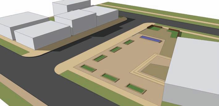
areas that can accommodate a curb (Fig. 7-27). Insure that the surface faces you defined for curbs are subdivided from the adjacent faces. 5. Create the walls and planters using the same technique you used to create the curbs.
Identify areas with walls, use the Offset tool to provide thickness, and (if needed) close off the ends by adding edges with the Line tool (Fig. 7-28, Fig. 7-29).
Fig. 7-26: Define ends of curb locations. Delete extra lines created from using the Offset tool.
Fig. 7-27: A curb is added to the site perimeter.
Fig. 7-28: Planter wall locations on the plan image.
Fig. 7-29: Offset the planter area faces to create edges for the wall.
Review the plan before you move on to the next step. If you missed anything or something needs to be adjusted, draft the necessary lines. Select faces that define locations to make sure they have been subdivided.
Create the Flatwork Base Group You’ll need the plan image to help identify and place components. However, adding colors or textures will obscure the plan image underneath. Therefore, before you add colors or textures to the faces, copy the Flatwork Base and place it next to the current base (Fig. 7-30). 1. Using a selection box, select the drafted edges and geometry that comprise the Flat-
work Base. Chapter 7: Detailed Site Plan Modeling
85


